2BCWO-SYR-0002The Halo device serves as an emergency call button
SafelyYou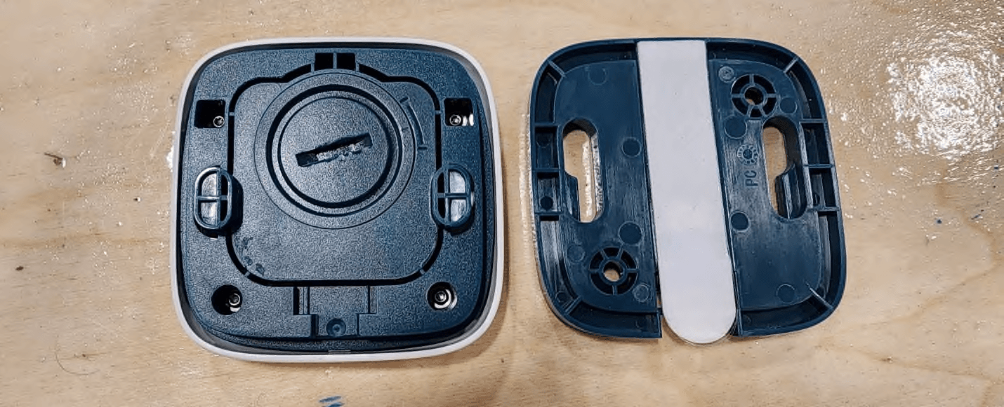
Click to zoom
Application Details
- Equipment Class
- DSS - Part 15 Spread Spectrum Transmitter
- Date of Grant
- Jun 23, 2026
- Application Purpose
- Original Equipment
- Equipment Note
- The Halo device serves as an emergency call button
- Frequency Range
- 902.30000000 - 914.90000000
- Company
- SafelyYou
- Country
- United States
Documents & Files
Document Text
Text extracted from the exhibit documents filed with the FCC. Open a document above to read the original.
Users Manual
User Manual Wall Button and Pendant safely-you.com | 415-579-3630 | 36 Clyde St, San Francisco, CA Rev 1.1 12/25 Overview The SafelyYou Halo™ Wall Button and Pendant are devices that are used by facility residents to request assistance from facility staff members. Users simply need to push and release the white area of the Wall Button or press and release the ribbed area of the clip on the Pendant to activate either device and transmit a request. Both of these devices are installed and activated by SafelyYou trained technicians. In the Box SafelyYou Halo™ Wall Button Wall Button Wall Plate Wall Plate Mounting Tape and Anchors with Screws SafelyYou Halo™ Pendant Pendant Lanyard Batteries are shipped separately and furnished by SafelyYou. A CR2450 coin cell battery is required for device operation. safely-you.com | 415-579-3630 | 36 Clyde St, San Francisco, CA Rev 1.1 12/25 Installation An installed and activated SafelyYou Halo™ Gateway is required prior to activation and installation of a SafelyYou Halo™ Wall Button or Pendant. Installation of all items should be performed by a SafelyYou trained technician. What You Will Need Activated Halo Gateway Drill with 15/64” bit Mini Phillips head screwdriver Mini slot head screwdriver Small Spirit Level SafelyYou Installation App Access to site network safely-you.com | 415-579-3630 | 36 Clyde St, San Francisco, CA Rev 1.1 12/25 Finding the appropriate installation location: It’s important to determine the best location for installation of the Wall Button. Locations will vary based on different area configurations. Ideal mounting locations include on walls at light switch or lower heights or as required by local standards in different regions. When installing the Wall Plate on drywall, mounting anchors and screws (included) are recommended while ensuring that there are no hidden obstructions behind the drywall. Installations on fiberglass, tile, similar surfaces or furniture are best suited for mounting tape (included). In all cases, please observe the correct direction of the Wall Plate using the arrows in the Wall Plate and ensure that the Wall Plate is installed level. Preparation: The SafelyYou authorized installer will use the installation App to activate these devices after Wall Plate installation and battery insertion. Battery Installation: Once the Wall Plate for the Wall Button is installed, the next steps of battery installation and activation with the installation app should follow. The Pendant battery should be installed prior to attaching the included clip and lanyard to the Pendant, followed by activation by the SafelyYou authorized installer with the installation app. See the following diagrams for battery installation in both devices. Battery removal and installation should only be performed by authorized representatives. Use a small slot head screwdriver in the provided slot under the clip to loosen the clip. Remove the clip and set it to one side. Using the same screwdriver from the prior step, use the slot provided under the battery door to carefully remove the battery door. safely-you.com | 415-579-3630 | 36 Clyde St, San Francisco, CA Rev 1.1 12/25 Install or replace the battery, placing it so that the positive side (marked with a +) is facing you. Replace the battery cover and the clip with lanyard. Wait up to one minute and verify that the LED illuminates blue. If the device has not yet been activated, follow the steps outlined in the next section. If the device has already been activated, resume normal use. ________________________________________________________________________________ Use a small slot head screwdriver in the provided slot under the Wall Button to remove it from the Wall Plate. Using the same screwdriver from the prior step or a properly-sized coin, use the slot provided in the round battery cover to carefully turn the cover counter-clockwise and then remove it. safely-you.com | 415-579-3630 | 36 Clyde St, San Francisco, CA Rev 1.1 12/25 Install or replace the battery, placing it so that the positive side (marked with a +) is facing you. Note the mark on the battery cover, lining it up with the upper mark on the rear of the Wall Button. Using the same screwdriver from the prior step, use the slot provided in the round battery cover to carefully turn the cover clockwise until the mark on it and the lower one on the rear of the button are aligned. Wait up to one minute and verify that the LED illuminates blue. If the device has not yet been activated, follow the steps outlined in the next section. If the device has already been activated, resume normal use. Initial Activation: Once the device has had a battery correctly installed, activation will be performed as follows. Up to one minute after battery installation, the device blue LED will start to blink once every two seconds. This indicates that the device is ready for the installer to begin system activation using a Bluetooth connection via the installation App. Once the App has connected to the device, the blue LED will switch to blinking twice every two seconds. Using the App, the installer will verify the ID and type (Wall Button or Pendant) of the device being activated. The QR code on the device will be scanned by the installer as an additional verification step to match the device to the one connected to the App. Once the prior steps are completed, the installer will assign the device to a user. For the Wall Button, the location of that device will then be selected. safely-you.com | 415-579-3630 | 36 Clyde St, San Francisco, CA Rev 1.1 12/25 As a final confirmation step of successful device activation, the device LED will blink green three times to verify successful connection to the Gateway. Note: If the device is unable to successfully connect to the Gateway, the device LED will blink red three times to indicate that the connection was unable to be established. The device will automatically retry to establish a connection to the Gateway. When that…
Text truncated - open the document above for the full version.
Attestation Statements
Date: 2026-06-03 To: Federal Communications Commission Authorization and Evaluation Division 7435 Oakland Mills Road Columbia, MD 21046 USA Ref: Attestation Statements Part 2.911(d)(7) Filing Applicant’s FRN #: 0034245316 FCC ID: 2BCWO-SYC-0001 SafelyYou, LLC (“the applicant”) certifies that, as of the date of the filing of the application, we designate ourselves as the U.S. agent for service of process. Designated U.S. Agent Information: Name: SafelyYou, LLC FRN #: 0034245316 Address: 36 Clyde Street, San Francisco, CA 94107 USA Contact Person: Karim Sammouda Tel.: +1 (415) 579-3630 Email: [email protected] Sincerely, Name: Karim Sammouda Title: Director of Hardware Engineering 36 Clyde Street San Francisco, CA 94107 [email protected] 415.579.3630
Attestation Statements
36 Clyde Street San Francisco, CA 94107 -.info@safely you com 415.579.3630 Federal Communications Commission Authorization and Evaluation Division 7435 Oakland Mills Road , 21046Columbia MD USA : 3Date June rd , 2026 : 2.911( )(5)( ) 2.911( )(5)( )Ref Attestation Statements Partd i and Partd ii : 2--0002FCC ID BCWO SYR 2.911( )(5)( )Partd i (“ ”) SafelyYou the applicant certi'es that the equipment for which authorization is soughtis not “” covered equipment anddoes not - contain anti virus software or cybersecurity software prohibited from receiving an equipment authorization pursuant to47 2.903CFR, 986446 01 KDBD Covered Equipment Guidance, (and FCC Covered List.. //www fcc gov supplychain coveredlist). 2.911( )(5)( )Partd ii (“ ”) , , SafelyYou the applicant certi'es that as of the date of the 'ling of the application the applicantis not ( identi'ed on the Covered List as a speci'cally named entity or any of its subsidiaries or ) “” .af'liates as an entity producing covered equipment ,Sincerely _______________________ Karim Sammouda
Cover Letter(s)
____________ 36 Clyde Street San Francisco, CA 94107 [email protected] 415.579.3630 FCC ID: 2BCWO-SYR-0002 Model declaration letter To whom it may concern, SafelyYou declares that Halo TM Wall Button, Model SYC-00046 and Halo TM Pendant, Model SYC-00047 use the same transmitters, the same PCBA, the same antennas, and the same electrical components. The only difference between the two part numbers is the device enclosure. Karim Sammouda _ _ _ ______ 2026-06-03
Cover Letter(s)
Date: 2026-05-13 To: Federal Communications Commission Authorization and Evaluation Division 7435 Oakland Mills Road Columbia, MD 21046 USA Confidentiality Request regarding application for certification of FCC ID: 2BCWO-SYR-0002 Pursuant to Sections 0.457(d)(1)(ii) and 0.459 of the Commission’s Rules, SafelyYou, LLC hereby requests permanent confidential treatment of information accompanying this application as outlined below: Schematics Bill of Materials/Parts List Block Diagrams Theory of Operation The above materials contain trade secrets and proprietary information not customarily released to the public. The public disclosure of these materials may be harmful to the applicant and provide unjustified benefits to its competitors. The applicant understands that pursuant to Section 0.457(d)(1)(ii) of the Rules, disclosure of this application and all accompanying documentation will not be made before the date of the Grant for this application. Sincerely, Name:Karim Sammouda Title:Director of Hardware Engineering 36 Clyde Street San Francisco, CA 94107 [email protected] 415.579.3630
Cover Letter(s)
Date: 2026-05-13 To: Federal Communications Commission Authorization and Evaluation Division 7435 Oakland Mills Road Columbia, MD 21046 USA Dear Sir or Madam, We, SafelyYou, LLC, hereby authorize Min Xie of Megalab Group Inc., 150 Addison Hall Circle, Aurora, Ontario, L4G 3X8, Canada; 905-752-1925 to act as our agent in all matters relating to applications for equipment authorization, including the signing of all documents relating to these matters. The authorization expires on 2027-02-11. Yours sincerely, Name: Karim Sammouda Title: Director of Hardware Engineering 36 Clyde Street San Francisco, CA 94107 [email protected] 415.579.3630
External Photos
Report No.: ML303547-RF00Issue Date: June 2, 2026 Megalab Group Inc. – 150 Addison Hall Circle, Aurora, Ontario, L4G 3X8, Canada www.megalabinc.com – (905) 752-1925 This report may not be reproduced, except in full, without prior written approval of Megalab Group Inc. Page 1 of 6 Client:SafelyYou Product Name/Model:Halo™Wall Button / SYC-00046 Halo™ Pendant / SYC-00047 FCC ID:2BCWO-SYR-0002 External Photos – Wall Button Figure 1 ‒ Top Figure 2 ‒ Bottom Report No.: ML303547-RF00Issue Date: June 2, 2026 Megalab Group Inc. – 150 Addison Hall Circle, Aurora, Ontario, L4G 3X8, Canada www.megalabinc.com – (905) 752-1925 This report may not be reproduced, except in full, without prior written approval of Megalab Group Inc. Page 2 of 6 Figure 3 ‒ Front Figure 4 ‒ Back/Bottom Report No.: ML303547-RF00Issue Date: June 2, 2026 Megalab Group Inc. – 150 Addison Hall Circle, Aurora, Ontario, L4G 3X8, Canada www.megalabinc.com – (905) 752-1925 This report may not be reproduced, except in full, without prior written approval of Megalab Group Inc. Page 3 of 6 Figure 5 ‒ Left Figure 6 ‒ Right Report No.: ML303547-RF00Issue Date: June 2, 2026 Megalab Group Inc. – 150 Addison Hall Circle, Aurora, Ontario, L4G 3X8, Canada www.megalabinc.com – (905) 752-1925 This report may not be reproduced, except in full, without prior written approval of Megalab Group Inc. Page 4 of 6 External Photos – Pendant Figure 7 ‒ Top Figure 8 ‒ Bottom Report No.: ML303547-RF00Issue Date: June 2, 2026 Megalab Group Inc. – 150 Addison Hall Circle, Aurora, Ontario, L4G 3X8, Canada www.megalabinc.com – (905) 752-1925 This report may not be reproduced, except in full, without prior written approval of Megalab Group Inc. Page 5 of 6 Figure 9 ‒ Front Figure 10 ‒ Back/Bottom Report No.: ML303547-RF00Issue Date: June 2, 2026 Megalab Group Inc. – 150 Addison Hall Circle, Aurora, Ontario, L4G 3X8, Canada www.megalabinc.com – (905) 752-1925 This report may not be reproduced, except in full, without prior written approval of Megalab Group Inc. Page 6 of 6 Figure 11 ‒ Left Figure 12 ‒ Right
ID Label/Location Info
Report No.: ML303547-RF00Issue Date: June 18, 2026 Megalab Group Inc. – 150 Addison Hall Circle, Aurora, Ontario, L4G 3X8, Canada www.megalabinc.com – (905) 752-1925 This report may not be reproduced, except in full, without prior written approval of Megalab Group Inc. Page 1 of 4 Client:SafelyYou Product Name/Model:Halo™Wall Button/ SYC-00046 Halo™ Pendant / SYC-00047 FCC ID:2BCWO-SYR-0002 Sample Label and Location Report No.: ML303547-RF00Issue Date: June 18, 2026 Megalab Group Inc. – 150 Addison Hall Circle, Aurora, Ontario, L4G 3X8, Canada www.megalabinc.com – (905) 752-1925 This report may not be reproduced, except in full, without prior written approval of Megalab Group Inc. Page 2 of 4 Figure 1 – Halo™ Wall Button Label Location Report No.: ML303547-RF00Issue Date: June 18, 2026 Megalab Group Inc. – 150 Addison Hall Circle, Aurora, Ontario, L4G 3X8, Canada www.megalabinc.com – (905) 752-1925 This report may not be reproduced, except in full, without prior written approval of Megalab Group Inc. Page 3 of 4 Report No.: ML303547-RF00Issue Date: June 18, 2026 Megalab Group Inc. – 150 Addison Hall Circle, Aurora, Ontario, L4G 3X8, Canada www.megalabinc.com – (905) 752-1925 This report may not be reproduced, except in full, without prior written approval of Megalab Group Inc. Page 4 of 4 Figure 2 – Halo™ Pendant Label Location
Internal Photos
Report No.: ML303547-RF00Issue Date: June 2, 2026 Megalab Group Inc. – 150 Addison Hall Circle, Aurora, Ontario, L4G 3X8, Canada www.megalabinc.com – (905) 752-1925 This report may not be reproduced, except in full, without prior written approval of Megalab Group Inc. Page 1 of 8 Client:SafelyYou Product Name/Model:Halo™Wall Button / SYC-00046 Halo™ Pendant / SYC-00047 FCC ID:2BCWO-SYR-0002 Internal Photos 1.Halo™ Wall Button Figure 1 – Cover Off – Wall Button Report No.: ML303547-RF00Issue Date: June 2, 2026 Megalab Group Inc. – 150 Addison Hall Circle, Aurora, Ontario, L4G 3X8, Canada www.megalabinc.com – (905) 752-1925 This report may not be reproduced, except in full, without prior written approval of Megalab Group Inc. Page 2 of 8 Figure 2 – Internal photo – Wall Button Figure 3 – Internal photo – Wall Button Report No.: ML303547-RF00Issue Date: June 2, 2026 Megalab Group Inc. – 150 Addison Hall Circle, Aurora, Ontario, L4G 3X8, Canada www.megalabinc.com – (905) 752-1925 This report may not be reproduced, except in full, without prior written approval of Megalab Group Inc. Page 3 of 8 Figure 4 – Antenna – Wall Button SubGig Antenna Report No.: ML303547-RF00Issue Date: June 2, 2026 Megalab Group Inc. – 150 Addison Hall Circle, Aurora, Ontario, L4G 3X8, Canada www.megalabinc.com – (905) 752-1925 This report may not be reproduced, except in full, without prior written approval of Megalab Group Inc. Page 4 of 8 2.Halo™ Pendant Figure 5 – Cover Off – Pendant Report No.: ML303547-RF00Issue Date: June 2, 2026 Megalab Group Inc. – 150 Addison Hall Circle, Aurora, Ontario, L4G 3X8, Canada www.megalabinc.com – (905) 752-1925 This report may not be reproduced, except in full, without prior written approval of Megalab Group Inc. Page 5 of 8 Figure 6 – Internal photo – Pendant Report No.: ML303547-RF00Issue Date: June 2, 2026 Megalab Group Inc. – 150 Addison Hall Circle, Aurora, Ontario, L4G 3X8, Canada www.megalabinc.com – (905) 752-1925 This report may not be reproduced, except in full, without prior written approval of Megalab Group Inc. Page 6 of 8 Figure 7 – PCB Antenna Front SubGig Antenna Report No.: ML303547-RF00Issue Date: June 2, 2026 Megalab Group Inc. – 150 Addison Hall Circle, Aurora, Ontario, L4G 3X8, Canada www.megalabinc.com – (905) 752-1925 This report may not be reproduced, except in full, without prior written approval of Megalab Group Inc. Page 7 of 8 PCB is identical between the Halo™ Wall Button and Halo™ Pendant Figure 8 – PCB Front Figure 9 – Transmitter top and bottom, Shield Removed Transmitter Report No.: ML303547-RF00Issue Date: June 2, 2026 Megalab Group Inc. – 150 Addison Hall Circle, Aurora, Ontario, L4G 3X8, Canada www.megalabinc.com – (905) 752-1925 This report may not be reproduced, except in full, without prior written approval of Megalab Group Inc. Page 8 of 8 Figure 10 – PCB Back Figure 11 – SubGig PCB Antenna Front Figure 12 – SubGig PCB Antenna Back BLE Antenna (PCB Trace) SubGig Antenna Connector
RF Exposure Info
Report No.: ML303547-RF00Issue Date: June 2, 2026 Megalab Group Inc. – 150 Addison Hall Circle, Aurora, Ontario, L4G 3X8, Canada www.megalabinc.com – (905) 752-1925 This report may not be reproduced, except in full, without prior written approval of Megalab Group Inc. Page 1 of 4 Client:SafelyYou Product Name/Model:Halo™Wall Button / SYC-00046 Halo™ Pendant / SYC-00047 FCC ID:2BCWO-SYR-0002 ReferenceFCC KDB 447498 D04 v01 FCC RF Exposure Where the Device Under Test (DUT) can be shown to meet the requirements for an exemption pursuant to FCC 47 CFR §1.1307(b)(3), an evaluation is not required with respect to the limits on human exposure to RF emissions provided in FCC 47 CFR §1.1310. 1.Determination of Exemption As per 47 CFR §1.1307(b)(3), for single RF sources (i.e., any single fixed RF source, mobile device, or portable device), a single RF source is exempt if: A.1-mW Test Exemption: The available maximum time-averaged power is no more than 1 mW, regardless of separation distance. This exemption may not be used in conjunction with other exemption criteria other than those in paragraph (b)(3)(ii)(A) of this section. Medical implant devices may only use this exemption and that in paragraph (b)(3)(ii)(A); B.SAR-Based Exemption: The available maximum time-averaged power or effective radiated power (ERP), whichever is greater, is less than or equal to the threshold P th (mW) described in the following formula. This method shall only be used at separation distances (cm) from 0.5 centimeters to 40 centimeters and at frequencies from 0.3 GHz to 6 GHz (inclusive). P th is given by: ( ) = ( 20 ⁄ ) ≤20 20 < ≤40 Where = − 60 And ( ) = 2040 0.3 ≤ <1.5 3060 1.5 ≤ ≤6 d = the minimum separation distance (cm) in any direction from any part of the device antenna(s) or radiating structure(s) to the body of the device user. Report No.: ML303547-RF00Issue Date: June 2, 2026 Megalab Group Inc. – 150 Addison Hall Circle, Aurora, Ontario, L4G 3X8, Canada www.megalabinc.com – (905) 752-1925 This report may not be reproduced, except in full, without prior written approval of Megalab Group Inc. Page 2 of 4 C.MPE-Based Exemption: Using Table 1 and the minimum separation distance (R in meters) from the body of a nearby person for the frequency (f in MHz) at which the source operates, the ERP (watts) is no more than the calculated value prescribed for that frequency. For the exemption in Table 1 to apply, R must be at least λ/2π, where λ is the free-space operating wavelength in meters. If the ERP of a single RF source is not easily obtained, then the available maximum time- averaged power may be used in lieu of ERP if the physical dimensions of the radiating structure(s) do not exceed the electrical length of λ/4 or if the antenna gain is less than that of a half-wave dipole (1.64 linear value). Table 1 of § 1.1307(b)(3)(i)(C) - Single RF Sources Subject to Routine Environmental Evaluation RF SourceFrequency (MHz) Threshold ERP (Watts) 0.3-1.341,920 R 2 1.34-303,450 R 2 /f 2 30-3003.83 R 2 300-1,5000.0128 R 2 f 1,500-100,00019.2 R 2 2.RF Exposure Evaluation The DUT is a device designed to be used in other than fixed locations and generally used in such a way that the RF source's radiating structure is within 40 centimeters of the body of the user. The Halo™ Wall Button is mobile and generally mounted on the wall where the end-user presses the button. The Halo™ Pendant is portable and worn around the neck where the end-user presses the button. The minimum separation distance from the radiating structure to any part of the body or extremity of a user is 10mm as stated by the manufacturer under normal operation. However, worst case measurement condition of 5mm separation distance is used for the exclusion analyses. 2.1Transmission Duty Cycle The SubGig transmitter has a maximum transmission duration of 0.2901 second in every 13.3 second. Which results in a duty cycle of 2.18% and a duty cycle correction factor (DCCF) of -16.61 dB. The duty cycle is source base and cannot be change by the user. See Halo RF Exposure by client in Appendix for additional details. Report No.: ML303547-RF00Issue Date: June 2, 2026 Megalab Group Inc. – 150 Addison Hall Circle, Aurora, Ontario, L4G 3X8, Canada www.megalabinc.com – (905) 752-1925 This report may not be reproduced, except in full, without prior written approval of Megalab Group Inc. Page 3 of 4 2.2DUT RF Output Power Transmitter protocol Evaluation Frequency (MHz) Max Conducted Power (dBm) Antenna Gain (dBi) DCCF (dB) Avg ERP (dBm) AVG ERP (mW) Minimum Separation Distance (cm) Lora DTS903.0021.101.52-16.613.862.430.5 Lora FHSS902.3021.551.52-16.614.312.700.5 BLE2402.001.642.5302.021.590.5 Note: 1.EIRP (dBm) = Sum of the conducted power (dBm) + Antenna Gain (dBi) 2.ERP (dBm) = EIRP (dBm) – 2.15 3.ERP (mW) = 10^((ERP(dBm))/10) 2.3SAR-Based Exemption 900MHz Transmitter Threshold: = 2040(0.903)( ( 0.5 20 ⁄ ) ( . ) √ . =8.28 Maximum average ERP of 2.70 mW is below the threshold of 8.28 mW. 2.4GHz Transmitter Threshold: = 3060 ( 0.5 20 ⁄ ) √ . =2.72 Maximum ERP of 1.59 mW is below the threshold of 2.72 mW. According to 47 CFR §1.1307(b)(3)(i)(B), each transmitter complies with the RF exposure test exemption. Per 47 CFR Section 1307(b)(3)(ii)(B), the DUT qualify for simultaneous exemption if the transmitters meet the following requirement: 2.70 8.28 + 1.59 2.72 = 0.91 < 1 The DUT qualifies for simultaneous transmission exemption. Report No.: ML303547-RF00Issue Date: June 2, 2026 Megalab Group Inc. – 150 Addison Hall Circle, Aurora, Ontario, L4G 3X8, Canada www.megalabinc.com – (905) 752-1925 This report may not be reproduced, except in full, without prior written approval of Megalab Group Inc. Page 4 of 4 3.Appendix – Transmission Duty Cycle Analysis 36 Clyde Street San Francisco, CA 94107 -.inf…
Text truncated - open the document above for the full version.
Test Report
Megalab Group Inc. – 150 Addison Hall Circle, Aurora, Ontario, L4G 3X8, Canada www.megalabinc.com – (905) 752-1925 This report may not be reproduced, except in full, without prior written approval of Megalab Group Inc. TRRF_FCC-ICES-247-FHSS_v1 RF Test Report Standard(s):FCC Part 15 Subpart 15.247 Unlicensed Intentional Radiators Issued To:SafelyYou 36 Clyde Street San Francisco, CA 94107 United States Product Name:Halo™ Wall Button and Halo™ Pendant Model(s):SYC-00046 and SYC-00047 FCC ID:2BCWO-SYR-0002 Report No.ML303547B-RF01 LoRa FHSS Date of Issue:June 2, 2026 Report Prepared By:ReviewedBy: Min Xie, Sr. EMC/RF Project Engineer Amir Emami, Project Engineer Report No.: ML303547B-RF00 LoRa FHSS Issue Date: June 2, 2026 Client: SafelyYou Page 2 of 72 Device Under Test: Halo™ Wall Button and Halo™ Pendant Table of Contents 1.Revision History .................................................................................................................................... 3 2.Summary of Test Results ....................................................................................................................... 4 2.1Test Verdict .................................................................................................................................. 4 2.2Test Standards ............................................................................................................................. 5 2.3Test Facility .................................................................................................................................. 6 3.General Information ............................................................................................................................. 9 3.1Client Information ....................................................................................................................... 9 3.2Device Under Test (DUT) ............................................................................................................. 9 3.3Test Setup of DUT ...................................................................................................................... 10 3.4Modifications for Compliance ................................................................................................... 10 4.Test Results ......................................................................................................................................... 11 4.1Emission Bandwidth .................................................................................................................. 11 4.2Channel Carrier Frequency Separation ..................................................................................... 22 4.3Number of Hopping Channels ................................................................................................... 27 4.4Time of Occupancy (Dwell Time) ............................................................................................... 32 4.5Peak Conducted Output Power ................................................................................................. 41 4.6Conducted Spurious Emissions (-20dBc) ................................................................................... 50 4.7Transmitter Spurious Radiated Emissions ................................................................................. 64 Report No.: ML303547B-RF00 LoRa FHSS Issue Date: June 2, 2026 Client: SafelyYou Page 3 of 72 Device Under Test: Halo™ Wall Button and Halo™ Pendant 1.Revision History Project No. & Revision Report Date Initials Description ML303547B-RF00 May 29, 2026 MX Initial Release ML303547B-RF01 June 2, 2026 MX Added test model to Section 3.3 Test Setup of DUT. NOTE: Latest reports marked as a revision replace any previous report and/or report revision issued under the same project number. Report No.: ML303547B-RF00 LoRa FHSS Issue Date: June 2, 2026 Client: SafelyYou Page 4 of 72 Device Under Test: Halo™ Wall Button and Halo™ Pendant 2.Summary of Test Results 2.1Test Verdict Unless otherwise stated, the test data and results in this test report relate only to the sample(s) tested. Requirement Test Type Result Remark FCC 15.203 15.247(b)(4) Antenna Gain and Requirement Pass Custom PCB antenna with 1.52dBi Gain 15.247(a)(1) Emission Bandwidth Pass 20 dB Bandwidth < 250kHz 15.247(a)(1) Channel Carrier Frequency Separation Pass ≥ MAX {25 kHz, BW20dB} 15.247(a)(1) Number of Hopping Channels Pass >50 15.247(a)(1) Time of Occupancy (Dwell Time) Pass < 0.4 s in 20s 15.247(b) Peak Conducted Output Power Pass < 1 Watt 15.247(d) Spurious Out of Band Emissions Pass < 20dBc 15.247(d) 15.209 Transmitter Spurious Radiated Emissions Pass --- 15.207 Power Line Conducted Emissions N/A DUT is a module which is DC powered from its host and does not connect to any mains network 2.1.1Test Verdict Notes and Justifications The DUT was mounted in three orthogonal axes and worst-case results were obtained in the Y-axis. Worst case results are presented. See the Test Setup Photos for axis details. Antenna details obtained from Client’s Antenna Datasheet. As per FCC 15.203, the antenna is a custom PCB trace antenna and has less than 6dBi gain. Report No.: ML303547B-RF00 LoRa FHSS Issue Date: June 2, 2026 Client: SafelyYou Page 5 of 72 Device Under Test: Halo™ Wall Button and Halo™ Pendant 2.2Test Standards Standard Description 47 CFR FCC Part 15 Subpart CCode of Federal Regulations –Radio Frequency Devices, Intentional Radiators FCC KDB 558074:2019Digital Transmission Systems, measurements and procedures ANSI C63.4:2014+C63.4a-2017Methods of Measurement of Radio-Noise Emissions from Low- Voltage Electrical and Electronic Equipment in the Range of 9 kHz to 40 GHz ANSI C63.10-2020+C63.10a- 2024 American National Standard of Procedures for Compliance Testing of Unlicensed Wireless Devices ISO 17025:2017General Requirements for the Competence of Testing and Calibration Laboratories Report No.: ML303547B-RF00 LoRa FHSS Issu…
Text truncated - open the document above for the full version.
Test Report
36 Clyde Street San Francisco, CA 94107 -.info@safely you com 415.579.3630 SYC-00051-R00 ________________________________________________ , LoRa antenna for Halo DESCRIPTION -00051-00 SafelyYou model number SYCR is an antenna designed for the LoRa protocol in the North , .American band adapted for the SafelyYou Halo product ELECTRICAL CHARACTERISTICS PARAMETERTYPICAL VALUEUNIT Frequency range902 - 928MHz ()Gain maxiumum1.52dBi Voltage standing wave ratio< 2 Efficiency> 60% Feed impedance50Ohms PolarizationLinear 36 Clyde Street San Francisco, CA 94107 -.info@safely you com 415.579.3630 TYPICAL RADIATION PATTERNS XY PATTERN YZ PATTERN
Test Setup Photos
Report No.: ML303547-RF00Issue Date: June 2, 2026 Megalab Group Inc. – 150 Addison Hall Circle, Aurora, Ontario, L4G 3X8, Canada www.megalabinc.com – (905) 752-1925 This report may not be reproduced, except in full, without prior written approval of Megalab Group Inc. Page 1 of 7 Client:SafelyYou Product Name/Model:Halo™Wall Button / SYC-00046 Halo™ Pendant / SYC-00047 FCC ID:2BCWO-SYR-0002 Test Setup Photos Report No.: ML303547-RF00Issue Date: June 2, 2026 Megalab Group Inc. – 150 Addison Hall Circle, Aurora, Ontario, L4G 3X8, Canada www.megalabinc.com – (905) 752-1925 This report may not be reproduced, except in full, without prior written approval of Megalab Group Inc. Page 2 of 7 Figure 1 ‒ Radiated Emissions Setup Report No.: ML303547-RF00Issue Date: June 2, 2026 Megalab Group Inc. – 150 Addison Hall Circle, Aurora, Ontario, L4G 3X8, Canada www.megalabinc.com – (905) 752-1925 This report may not be reproduced, except i…
Text truncated - open the document above for the full version.
Contact Information
Applicant
Karim Sammouda
[email protected]Fax: 5149475644
Technical Contact
SafelyYou, LLCKarim Sammouda
36 Clyde Street · San Francisco, California, 94107 · United States
Test Firm
Megalab Group Inc.Raymond Au
Technical Specifications
| # | Rule Parts | Frequency Range | Power Output |
|---|---|---|---|
| 1 | 15C | 902.3 MHz - 914.9 MHz | 142.89 mW |
Other Applications from SafelyYou
2BCWO-SYR-0001
May 29, 2026IP Network Camera
Equipment Class
DSS - Part 15 Spread Spectrum Transmitter
2BCWO-SYC-0001
Mar 17, 2026The Halo device serves as an emergency call button
Equipment Class
DSS - Part 15 Spread Spectrum Transmitter
2BCWO-ACPWM-100
Dec 11, 2023IP Network Camera
Equipment Class
DTS - Digital Transmission System