2BD2B-ARMA-08The Arma device is a blood pressure monistor designed for home use only. Results are shown on the LCD display as well as sent via Bluetooth to a connected smart phone once the test is complete.
Tournicare Pty Ltd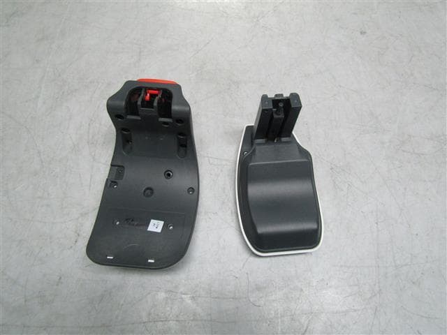
Click to zoom
Application Details
- Equipment Class
- DTS - Digital Transmission System
- Date of Grant
- Oct 10, 2024
- Application Purpose
- Original Equipment
- Date of Application
- Oct 09, 2024
- Equipment Note
- The Arma device is a blood pressure monistor designed for home use only. Results are shown on the LCD display as well as sent via Bluetooth to a connected smart phone once the test is complete.
- Frequency Range
- 2402.00000000 - 2480.00000000
- Company
- Tournicare Pty Ltd
- Country
- Australia
Documents & Files
Document Text
Text extracted from the exhibit documents filed with the FCC. Open a document above to read the original.
Attestation Statements
Rev 1/26/2023 Federal Communications Commission Authorization and Evaluation Division 7435 Oakland Mills Road Columbia, MD 21046 USA Date: 14 September 2024 Ref: Attestation Statements Part 2.911(d)(5)(ii) Filing FCC ID: 2BD2B-ARMA-08 Niels Van Sparrentak of Tournicare Pty Ltd (“the applicant”) certifies that, as of the date of the filing of the application, the applicant is not identified on the Covered List as a specifically named entity or any of its subsidiaries or affiliates as an entity producing “covered” equipment. Sincerely, Niels Van Sparrentak – CEO Tournicare Pty Ltd
Attestation Statements
Rev 1/26/2023 Federal Communications Commission Authorization and Evaluation Division 7435 Oakland Mills Road Columbia, MD 21046 USA Date: 25 September 2024 Ref: Attestation Statements Part 2.911(d)(5)(i) Filing FCC ID: 2BD2B-ARMA-08 Niels Van S parrentak of Tournicare Pty Ltd (“the applicant”) certifies that the equipment for which authorization is sought is not “covered” equipment prohibited from receiving an equipment authorization pursuant to section 2.903 of the FCC rules. Niels Van Sparrentak of Tournicare Pty Ltd (“the applicant”) certifies that the equipment for which authorization is sought does not include cybersecurity or anti-virus software produced or provided by Kaspersky Lab, Inc. or any of its successors and assignees, including equipment with integrated Kaspersky Lab, Inc. (or any of its successors and assignees) cybersecurity or anti-virus software pursuant to DA-24- 886 and KDB 986446 D01 Covered Equipment Guidance section B(2a). Sincerely, Niels Van Sparrentak – CEO Tournicare Pty Ltd
Attestation Statements
Certification designating a U.S. Agent for service of process: As required by section 2.911(d)(7), the applicant must designate a contact located in the United States for purposes of acting as the applicant’s agent for service of process, regardless of whether the applicant is a domestic or foreign entity. An applicant located in the United States may designate itself as the agent for service of process. In either scenario, the designation of the U.S. agent for service of process should be provided as an attachment to the equipment authorization application. The applicant must provide a written certification, which must: i. B e signed by both the applicant and designated agent for service of process, if the agent is different from the applicant. ii. A cknowledge the applicant’s consent and the designated agent’s obligation to accept service of process. iii. P rovide a physical U.S. address and email for the designated agent. iv . A cknowledge the applicant’s acceptance to maintain an agent for no less than one year after the grantee has terminated all marketing and importation or the conclusion of any Commission-related proceeding involving the equipment. Unofficial information provided by FCC personnel on February 14, 2023, via the monthly call with the TCB Council: The Agent for Process of Service: •cannot be a TCB or affiliated with a TCB (e.g. could not be a person who works for a TCB or a company that owns or is owned by the TCB) •cannot be a [FCC recognised] Lab or affiliated with a test lab (e.g. could not be a person who works for a Lab or a company that owns or is owned by the Lab) •Agent can be Individual Entity or a Company Entity •Agent Entity must be located in US, US address/phone •Entity acting as Agent must have FRN (best practice, put FRN on Agent Letter) •Agent letter does not have to be FCC ID specific, can be general Agent for Grantee For devices being marketed or for which marketing has ceased for less than 1 year, if the Agent for Process of Service changes, then for every TC Number the TCB must request the FCC to put application into Audit Mode and Agent Letter needs to be updated (superseded). NOTE: The U.S. Agent for Service of Process should not be confused with the authorized agent used for signing the 731 form, other cover letters within the application, and/or the agent who may interface with the TCB. U.S. Agent Designation for Service of Process ATTENTION: Federal Communications Commission Authorization and Evaluation Division 7435 Oakland Mills Road Columbia, MD 21046 USA REGARDING: FCC Certification – Secti on 2.911(d)(7) Information Designated U.S. Agent Company Name: Approve-IT, I nc. Contact Name: Nathan Grinager Street Address: 8011 34 th Ave S outh, Suite 342 City/Province/Zip: Bloomington, MN 55425 Telephone No: 651- 247-1678 Email: [email protected] FRN #: 0 027533835 This letter is to confirm that we (“the Designated U.S. Agent) have a ccepted the responsibility to act as the Designated U.S. Agent for Service of Process as required by section 47 C FR 2.911(d)(7) on b ehalf of the Applicant n oted below. U.S. Agent Signature: Date: Signed by (Printed Name/Title): Nathan Grinager / Co-President The Applicant confirms its explicit consent and acknowledges that they must maintain an agent for no less than one year after terminating all marketing and importation OR the conclusion of any Commission-related proceed ing involvi ng the equipment. The applicant further acknowledges their responsibility to inform the FCC whenever the Desig nated U.S. Agent information above changes. Applicant Company name: Tournicare Pty Ltd Grantee FRN: 0034152926 FCC ID: 2BD2B-ARMA-08 Contact Name: Niels Van S parrentak Street Address: 18 Elliott Ave, Balwyn, 3103, Australia City/Province/Zip: Balwyn, 3103 Telephone No: +61 414 3 73793 Email: [email protected] Applicant Signature: Date: 14 May 2024 Signed by (Printed Name/Title): Niels van Sparrentak CEO 15 May, 2024 *This letter must be dated within 1 year of the date the device is submitted to the TCB for device certification.
Cover Letter(s)
Federal Communications Commission Authorization and Evaluation Division 7435 Oakland Mills Road Columbia, MD 21046 USA Date: 12 September 2024 SUBJECT: FCC Application for 2BD2B-ARMA-08 To Whom It May Concern: We, the undersigned, hereby authorize Shabbir Ahmed at EMC Technologies Pty Ltd to act on our behalf, to apply to the Federal Communications Commission for FCC approval of our equipment. Any and all acts carried out by Shabbir Ahmed at EMC Technologies on our behalf shall have the same effect as acts of our own. This is to advise that we are in full compliance with the Anti- Drug Abuse Act. We, the applicant, are not subject to a denial of federal benefits pursuant to Section 5301 of the Anti-Drug Act of 1988, 21 USC853a, and no party to the application is subject to a denial of federal benefits pursuant to that section. Regards, Niels Van Sparrentak – CEO Tournicare Pty Ltd
Cover Letter(s)
Federal Communications Commission Authorization and Evaluation Division 7435 Oakland Mills Road Columbia, MD 21046 USA Date: 12 September 2024 SUBJECT: FCC Application for 2BD2B-ARMA-08 To Whom It May Concern: As per KDB 784748 D01, Section 3, we, the undersigned, hereby request permission to exclude the FCC 15.19 compliance statement from our device. The device (16cm x 10cm x 9.5cm) and label (7.5cm x 3.5cm) are extremely small and does not utilize electronic labeling. The FCC 15.19 compliance statement shall be placed in the user manual). Regards, Niels Van Sparrentak – CEO Tournicare Pty Ltd
Cover Letter(s)
Fede ral Communications Commission Authorization and Evaluation Division Date: 17 September 2024 Confidentiality Request regarding application for certification of FCC ID: 2BD2B-ARMA-08 Pursuant to Sections 0.457 and 0.459 of the Commission’s Rules, we hereby request confidential treatment of information accompanying this application as outlined below: Exhibit Type Block Diagram Schematics Operational Description File Name CONF_ARMA Block Diagram.pdf CONF_ARMA Schematics.pdf CONF_ARMA_190_1234_01_Operational Description.pdf The above materials contain trade secrets and proprietary information not customarily released to the public. The public disclosure of these materials may be harmful to the applicant and provide unjustified benefits to its competitors. The applicant understands that pursuant to Section 0.457 of the Rules, disclosure of this application and all accompanying documentation will not be made before the date of the Grant for this application. Pursuant to DA04-1705 June 15, 2004 of the Commission’s public notice, we also request temporary confidential treatment of information accompanying this application as outlined below for a period of 180 days: Exhibit Type Internal Photos Manual File Name CONFE2207-1563-3 Annex B.pdf ARMA-IFU, Version 4.pdf Sinc erely, Niels Van Sparrentak – CEO Tournicare Pty Ltd
Cover Letter(s)
EMC Technologies Pty. Ltd. ABN 82 057 105 549 Melbourne 176 Harrick Road Keilor Park, Vic 3042 Tel: +61 3 9365 1000 Sydney Unit 3/87 Station Road Seven Hills, NSW 2147 Tel: +61 2 9624 2777 Email: [email protected] Web: www.emctech.com.au EMC Technologies Pty Ltd, 176 Harrick Road, Keilor Park VIC 3042 Australia www.emctech.com.au To Federal Communications Commission Attention: Certification Officer EMCT Ref: M2211017 Date: September 24, 2024 Subject: Tournicare Pty Ltd Request for Original Certification - FCC ID:2BD2B-ARMA-08 Product Name: ARMA Blood Pressure Monitor Model: 08 FCC ID: 2BD2B-ARMA-08 Transmitter: STM32WB55RGV6 Bluetooth Low Energy (BLE v5.2) Operating band: 2400 – 2483.5 MHz Antenna: AN3359 copper trace (STMicroelectronics) – 1.96 dBi Description: (supplied by customer) The ARMA device is a blood pressure monitor designed for home use only. Results are shown on the LCD display as well as sent via Bluetooth to a connected smart phone once the test is complete. Please Note: Permanent Confidentiality: Application includes request for permanent confidentiality – Operational Description, Schematics, Block Diagram Short-Term Confidentiality: Application includes request for short-term confidentiality (180 days) Internal photos: CONFE2207-1563-3 Annex B.pdf User Manual: ARMA-IFU, Version 4.pdf FCC 15.19 statement – exclusion request: Application includes request to omit the FCC 15.19 (a)(3) statement from the device label. Agent: EMC Technologies is acting as agent for Tournicare Pty Ltd in this application. Regards _____________ Shabbir Ahmed CEO EMC Technologies Pty Ltd 176 Harrick Road, Keilor Park, VIC 3042 Australia Ph: +61 3 9365 1000 www.emctech.com.au
External Photos
Page 1 of 4 EMC ENGINEERS & LABORATORIES EMC Bayswater Pty Ltd 18/88 Merrindale Drive Croydon South, Victoria, 3136, Australia Telephone: +61 3 9761 5888 Facsimile: +61 3 8761 6547 Email: [email protected] ABN: 49 112 221 333 Photograph Annex A: External - EUT Photographs Tournicare Pty Ltd 08 ARMA REPORT: E2207-1563-3 Annex A DATE: September, 2024 EMC Bayswater Test Report E2207-1563-3 Annex A Page 2 of 4 This document may not be reproduced, except in full, without written approval from EMC Bayswater Pty Ltd. Photographs Number Photograph Description 1 EUT – External views 2 3 4 5 6 7 8 9 10 EMC Bayswater Test Report E2207-1563-3 Annex A Page 3 of 4 This document may not be reproduced, except in full, without written approval from EMC Bayswater Pty Ltd. Photograph 1 Photograph 2 Photograph 3 Photograph 4 Photograph 5 Photograph 6 EMC Bayswater Test Report E2207-1563-3 Annex A Page 4 of 4 This document may not be reproduced, except in full, without written approval from EMC Bayswater Pty Ltd. Photograph 7 Photograph 8 Photograph 9 Photograph 10
ID Label/Location Info
ARMA LABEL LABEL POSITIONED ON THE INNER ASPECT OF THE LARGER LEG OF THE C-CLAMP. LABEL MATERIAL: THERMLfilm SELECT 22720 MANUFACTUROR: Flexcon LABELLING METHOD: The labelling method is a self adhesive label. Using a thermal transfer print method. AU Automatic Blood Pressure Monitor Tournicare Pty Ltd 18 Elliot Avenue, Balwyn Victoria, Australia 3101 DD MMM YYYY Rating: IP22 DC 5V 500mA Type BF Applied Part ARMA-08 FRM-063, Version 3 FCC ID: 2BD2B-ARMA-08 AU Automatic Blood Pressure Monitor Tournicare Pty Ltd 18 Elliot Avenue, Balwyn Victoria, Australia 3101 DD MMM YYYY Rating: IP22 DC 5V 500mA Type BF Applied Part ARMA-08 FRM-063, Version 3 FCC ID: 2BD2B-ARMA-08
RF Exposure Info
Page 1 of 8 EMC ENGINEERS & LABORATORIES EMC Bayswater Pty Ltd 18/88 Merrindale Drive Croydon South, Victoria, 3136, Australia Telephone: +61 3 9761 5888 Facsimile: +61 3 8761 6547 Email: [email protected] ABN: 49 112 221 333 RF Radiation Exposure Evaluation In accordance with: CFR47 FCC Part 2, Subpart J, 2.1093 FCC KDB 447498 D01 v06 Tournicare Pty Ltd 08 ARMA FCC ID: 2BD2B-ARMA-08 REPORT: E2207-1563-4 Rev1 DATE: September, 2024 This report replaces the previously issued report E2207-1563-4. Please refer to section 2 of this report for details of any previously issued reports. EMC Bayswater Test Report E2207-1563-4 Rev1 Page 2 of 8 Prepared by: Approved by: 24/09/2024 13:54 Adnan Zaman (EMC Test Engineer) Neville Liyanapatabendige (Manager) Date This document may not be reproduced, except in full, without written approval from EMC Bayswater Pty Ltd. RF Radiation Exposure Evaluation Report EMC Bayswater Test Report: E2207-1563-4 Rev1 Issue Date: September, 2024 Product: ARMA Model No: 08 Serial No: LIM+08 FCC ID: 2BD2B-ARMA-08 Client Details: Mr. Niels Van Sparrentak Tournicare Pty Ltd 18 Elliott Ave, Balwyn VIC 3103 Australia Phone No: +61 (0) 414 373 793 e-mail: [email protected] Standard(s): CFR47 FCC Part 2, Subpart J, 2.1093 Radiofrequency radiation exposure evaluation: portable devices. FCC KDB 447498 D01 v06 RF EXPOSURE PROCEDURES AND EQUIPMENT AUTHORIZATION POLICIES FOR MOBILE AND PORTABLE DEVICES Results Summary: RF Radiation exposure requirements Complied Test Date(s): 28 th of October, 2022 Test House (Issued By): EMC Bayswater Pty Ltd 18/88 Merrindale Drive Croydon South Victoria, 3136 Australia FCC Accredited Test Firm Registration number: 527798 FCC Accredited Test Firm Designation number: AU0004 Phone No: +61 3 9761 5888 Email: [email protected] Fax: +61 3 8761 6547 Web: www.emcbayswater.com.au The Tournicare Pty Ltd, 08, ARMA, measured EIRP/customer declared power is below the SAR exception threshold (5mm distance) and the calculated power density level at a distance of 20cm are below the maximum levels allowed by regulations therefore complied with the requirements of CFR47 FCC Part 2, Subpart J, 2.1093. This is to certify that the necessary evaluations were made by EMC Bayswater Pty Ltd, and that the Tournicare Pty Ltd, 08, ARMA, has been tested in accordance with requirements contained in the appropriate commission regulations. EMC Bayswater Test Report E2207-1563-4 Rev1 Page 3 of 8 This document may not be reproduced, except in full, without written approval from EMC Bayswater Pty Ltd. RF Radiation Exposure Evaluation for Tournicare Pty Ltd Contents 1. Introduction ................................................................................................................... 4 2. Test Report Revision History ........................................................................................ 4 3. Report Information ........................................................................................................ 4 4. Product Details .............................................................................................................. 5 4.1. Product Sample Details ........................................................................................... 5 4.2. Product description .................................................................................................. 5 5. SAR and RF Exposure exception evaluation ............................................................... 6 5.1. SAR exception evaluation ........................................................................................ 6 5.2. RF Exposure Evaluation (MPE) ............................................................................... 7 6. Conclusion ..................................................................................................................... 8 EMC Bayswater Test Report E2207-1563-4 Rev1 Page 4 of 8 This document may not be reproduced, except in full, without written approval from EMC Bayswater Pty Ltd. 1. Introduction RF Radiation Exposure evaluation was performed on a Tournicare Pty Ltd, 08, ARMA in accordance with CFR47 FCC Part 2, Subpart J, 2.1093. 2. Test Report Revision History ISSUE DATE Description AUTHORISED BY E2207-1563-4 25-08-2023 Original Neville Liyanapatabendige (Manager) E2207-1563-4 Rev1 24-09-2024 As per the customer’s request, product name, model number and customer details were updated, and the FCC ID was corrected. Neville Liyanapatabendige (Manager) 3. Report Information EMC Bayswater Pty Ltd reports apply only to the specific samples tested under the stated test conditions. All samples tested were in good operating condition throughout the entire test program unless otherwise stated. EMC Bayswater Pty Ltd does not in any way guarantees the later performance of the product/equipment. It is the manufacturer's responsibility to ensure that additional production units of the tested model are manufactured with identical electrical and mechanical components. EMC Bayswater Pty Ltd shall have no liability for any deductions, inference or generalisations drawn by the clients or others from EMC Bayswater Pty Ltd issued reports. This report shall not be used to claim, constitute or imply product endorsement by EMC Bayswater Pty Ltd. This report shall not be reproduced except in full, without the written approval of EMC Bayswater Pty Ltd. This document may be altered or revised by EMC Bayswater Pty Ltd personnel only, and shall be noted in the revision section of the document. Any alteration of this document not carried out by EMC Bayswater Pty Ltd will nullify the document. EMC Bayswater Test Report E2207-1563-4 Rev1 Page 5 of 8 This document may not be reproduced, except in full, without written approval from EMC Bayswater Pty Ltd. 4. Product Details 4.1. Product Sample Details The device, as supplied by the client, is described as follows: Product: ARMA Model No: 08 Serial No: LIM+08 Firmware: firmware…
Text truncated - open the document above for the full version.
Test Report
Page 1 of 87 EMC Bayswater Pty Ltd EMC ENGINEERS & LABORATORIES 18/88 Merrindale Drive Croydon South, Victoria, 3136, Australia Telephone: +61 3 9761 5888 Facsimile: +61 3 8761 6547 Email: [email protected] ABN: 49 112 221 333 RADIO COMPLIANCE REPORT Certification Test Report In accordance with: CFR47 FCC Part 15, Subpart C, 15.247 Tournicare Pty Ltd 08 ARMA FCC ID: 2BD2B-ARMA-08 REPORT: E2207-1563-3 Rev1 DATE: September, 2024 This report replaces the previously issued report E2207-1563-3. Please refer to section 2 of this report for details of any previously issued reports. Accreditation Number: 18553 Accredited for compliance with ISO/IEC 17025 - Testing The results of the tests, calibrations and/or measurements included in this document are traceable to Australian/national standards. NATA is a signatory to the ILAC Mutual Recognition Arrangement for the mutual recognition of the equivalence of testing and calibration reports. This document may not be reproduced except in full without approval from EMC Bayswater, with the exception of the certificate on page 2. EMC Bayswater Test Report E2207-1563-3 Rev1 Page 2 of 87 Prepared & tested by: Approved by: 24/09/2024 13:40 Adnan Zaman (EMC Test Engineer) Neville Liyanapatabendige (Manager) Date Accreditation number: 18553. The results of the tests, calibrations and/or measurements included in this document are traceable to Australian/national standards. NATA is a signatory to the ILAC Mutual Recognition Arrangement for the mutual recognition of the equivalence of testing, calibration and inspection reports. This document may not be reproduced except in full without approval from EMC Bayswater, with the exception of the certificate on page 2. Certificate of Compliance Certification Compliance Report EMC Bayswater Test Report: E2207-1563-3 Rev1 Issue Date: September, 2024 Test Sample(s): ARMA Model No: 08 Serial No: LIM+08 FCC ID: 2BD2B-ARMA-08 Client Details: Mr. Niels Van Sparrentak Tournicare Pty Ltd 18 Elliott Ave, Balwyn VIC 3103 Australia Phone No: +61 (0) 414 373 793 e-mail: [email protected] Test Specification: CFR47 FCC Part 15, Subpart C, 15.247 Results Summary: 15.203 - Antenna requirement Complied 15.247 (a)(2) - 6dB Bandwidth Complied 15.247 (b)(3) - Maximum Output Power Complied 15.247 (d) - Out-of-Band Emissions - – 100kHz, -20dBc Complied 15.247 (d) - Emissions on the Band edge Complied 15.247 (d), 15.209 - Radiated emissions in Restricted bands Complied 15.247 (e) - Power Spectral Density Complied 15.247 (i) - Radio frequency hazard Complied Test Date(s): 26 th to 28 th of October, 2022 Test House (Issued By): EMC Bayswater Pty Ltd 18/88 Merrindale Drive Croydon South Victoria 3136 Australia FCC Accredited Test Firm Registration number: 527798 FCC Accredited Test Firm Designation number: AU0004 Phone No: +61 3 9761 5888 e-mail: [email protected] Fax No: +61 3 8761 6547 Web: www.emcbayswater.com.au/ This is to certify that the necessary measurements were made by EMC Bayswater Pty Ltd, and that the Tournicare Pty Ltd, 08, ARMA, has been tested in accordance with requirements contained in the appropriate commission regulations. EMC Bayswater Test Report E2207-1563-3 Rev1 Page 3 of 87 Accreditation number: 18553. The results of the tests, calibrations and/or measurements included in this document are traceable to Australian/national standards. NATA is a signatory to the ILAC Mutual Recognition Arrangement for the mutual recognition of the equivalence of testing, calibration and inspection reports. This document may not be reproduced except in full without approval from EMC Bayswater, with the exception of the certificate on page 2. Radio Compliance Report for Tournicare Pty Ltd Contents 1. Introduction ................................................................................................................... 5 2. Test Report Revision History ........................................................................................ 5 3. Report Information ........................................................................................................ 5 4. Summary of Results ...................................................................................................... 5 5. Product Sample Details ................................................................................................. 6 5.1. EUT Description........................................................................................................ 6 5.2. Product description ................................................................................................... 6 5.3. Support Equipment ................................................................................................... 7 5.4. Product operating modes .......................................................................................... 7 5.5. Product operating mode for testing ........................................................................... 7 5.6. Configuration ............................................................................................................ 7 5.7. Modifications ............................................................................................................. 7 6. Test Facility & Equipment ............................................................................................. 8 6.1. Test Facility .............................................................................................................. 8 6.2. Test Equipment ........................................................................................................ 8 7. Referenced Standards ................................................................................................... 8 8. Referenced Documents ................................................................................................. 8 9. Antenna Requirement – FCC Part 15.203 ..................................................................... 9…
Text truncated - open the document above for the full version.
Test Report
Introduction This application note is dedicated to the STM32WB Series microcontrollers. One of the main reasons to use a PCB (printed circuit board) antenna is the reduced overall cost of the radio module. Well designed and implemented PCB-printed antennas have a similar performance to the SMD (surface-mounted device) ceramic equivalence. In general, the footprint for a ceramic SMD antenna is smaller than that for a PCB-printed variant. For a PCB-printed antenna solution, the increased size of the PCB in relation to space required for the antenna means that the radio module is larger and the cost of the PCB increased. However the PCB solution is generally cheaper than a SMD ceramic antenna. The demonstration and development boards for the STM32WB Series implement PCB printed antenna based on this application note. Low cost PCB antenna for 2.4 GHz radio: meander design for STM32WB Series AN5129 Application note AN5129 - Rev 4 - April 2019 For further information contact your local STMicroelectronics sales office. www.st.com 1General information This document applies to STM32WB Series Arm ® -based devices. Note:Arm is a registered trademark of Arm Limited (or its subsidiaries) in the US and/or elsewhere. AN5129 General information AN5129 - Rev 4 page 2/22 2Coordinate system For the purpose of this document, the spherical coordinate system illustrated in the figure below is used. Figure 1. Spherical coordinate system The PCB module is orientated vertically (plane X-Z) and located in proximity to the origin of the coordinate system. The azimuth angle radiates from the X-axis towards the Y-axis and the elevation angle radiates from the Z-axis towards the horizontal X-Y plane. Sometimes, as with geographical and navigational systems, the X-axis is called the "Nord-axis", the Yaxis is called the "East-axis" and the Z-axis is called the "Zenith-axis". AN5129 Coordinate system AN5129 - Rev 4 page 3/22 3Layout specification The PCB antennas, including the electrical parameters of PCB materials used, are layout sensitive. It is recommended to use a layout as close as possible to the one shown in the figure below. Figure 2. PCB antenna dimensions (in mm) The electrical parameters and performance of the PCB antenna are also determined by the substrate used, in particular the thickness of the core and dielectric constants. AN5129 Layout specification AN5129 - Rev 4 page 4/22 The figure below illustrates a typical cross-section of the substrate in a PCB-antennae area. Figure 3. PCB cross section at antennae area A substrate with the parameters as defined in the table below is recommended. Table 1. Recommended substrate specification Layer Dimensions Dielectric constant Ɛ R LabelValue (mil)Value (μm) Solder mask, topS10.717.784.4 Copper traceT1.640.64- CoreC28711.24.4 Solder mask, bottomS20.717.784.4 AN5129 Layout specification AN5129 - Rev 4 page 5/22 4Impedance matching Meander-like PCB antenna can be tuned to the required 50 Ω impedance by matching the impedance circuitry with the π topology. In Figure 2, the impedance matching area is marked with a dashed line. Under nominal conditions, this antenna exhibits and impedance very close to the required nominal impedance (50 Ω). To check the performance of this design, a sample antenna was manufactured (according to the specifications covered by this document). The figure below shows this antenna. Figure 4. Part of 802.15.4 and BLE PCB with meander-like antenna (scale around 4:1) Assuming that the manufactured sample exhibits the expected performance (no impedance matching necessary), the impedance matching circuitry is bypassed by two 100 pF capacitors connected in series, as shown in the figure below. Figure 5. Bypassing impedance matching circuitry - Direct RF connection All electrical parameters of the meander-like antenna have been measured at connection to the band-pass filter (BPF) with the frequency span covering frequencies from 2.4 GHz to 2.5 GHz. AN5129 Impedance matching AN5129 - Rev 4 page 6/22 Complex impedance of the antenna is shown in the Smith diagram in the figure below. Figure 6. Complex impedance of the meander-like antenna (Smith chart) The figure below shows the magnitude of the S11 parameter (in log scale). Figure 7. S11 parameter in logarithmic scale (Cartesian plot) AN5129 Impedance matching AN5129 - Rev 4 page 7/22 The figure below shows the standing wave ratio (SWR). Figure 8. Antenna standing wave ratio (SWR) The following changes affect the radiation impedance of the PCB antenna: • slight board size variation • metal shielding • use of plastic cover • presence of other components in proximity of the antenna The best performance impedance matching circuitry compensates these effects so that, for operating frequencies, the optimum 50 Ω impedance is achieved. AN5129 Impedance matching AN5129 - Rev 4 page 8/22 5Radiation pattern, 3-D visualization A three-dimensional (3-D) visualization of the radiation pattern (magnitude of the electrical far field |E|) is done for the center ISM band frequency 2.44175 GHz. Figure 9. 3-D radiation pattern overview Figure 10. Radiation pattern on X-Z plane AN5129 Radiation pattern, 3-D visualization AN5129 - Rev 4 page 9/22 6Radiation pattern, 2-D visualization In this section, all radiation patterns are related to the magnitude of electrical far field |E|, that is normalized and shown in the logarithmic scale (in dB). This means that the maximum global radiation pattern (maximum magnitude of the electrical far-field E) is represented by 0 dB level. To show the antenna radiation patterns in detail, three two dimensional (2-D) major cuts are presented. Consider the orientation of the module in the spherical coordinate system as shown in Figure 1. A three dimensional (3-D) far field radiation pattern is visualized as three two dimensional (2-D) cuts through a 3- D pattern. The following major planes are used for these cuts (see Figure 11): • one horizontal X-Y plane • two vertical planes: X-Z plan…
Text truncated - open the document above for the full version.
Test Setup Photos
Page 1 of 4 EMC ENGINEERS & LABORATORIES EMC Bay…
Text truncated - open the document above for the full version.
Contact Information
Applicant
Niels Van Sparrentak
Test Firm
EMC Bayswater Pty LtdNeville Liyanapatabendige
Technical Specifications
| # | Rule Parts | Frequency Range | Power Output |
|---|---|---|---|
| 1 | 15C | 2.40 GHz - 2.48 GHz | 2.50 mW |