2BDCB-P5000PLUSPortable power station
Shenzhen Yunji New Energy Technology Co., Ltd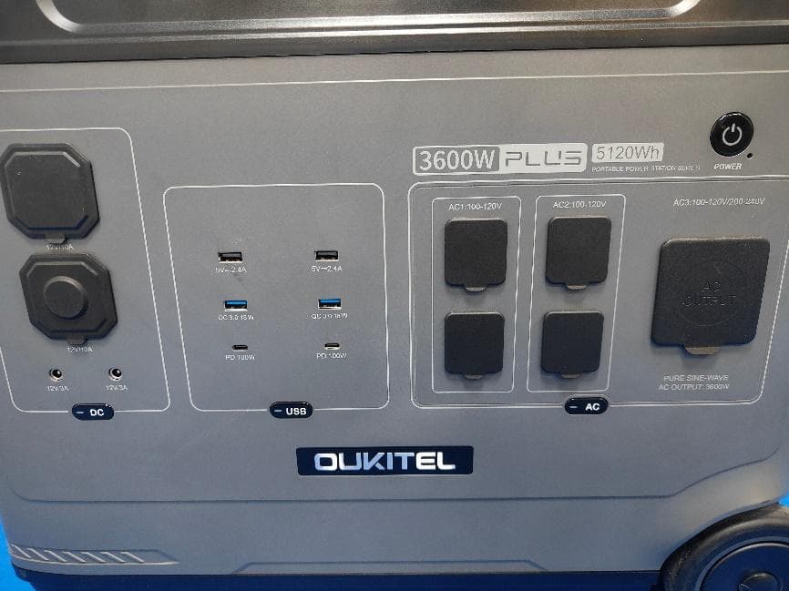
Click to zoom
Application Details
- Equipment Class
- DTS - Digital Transmission System
- Date of Grant
- Sep 09, 2026
- Application Purpose
- Original Equipment
- Equipment Note
- Portable power station
- Frequency Range
- 2402.00000000 - 2480.00000000
- Country
- China
Documents & Files
Document Text
Text extracted from the exhibit documents filed with the FCC. Open a document above to read the original.
Users Manual
PLUS P5000PLUS(US)V1.0 14 8 10 12 15 53KG AC1:120V 1800W (Max) AC2:120V 1800W (Max) AC3:120/240V 3600W (Max) 120V/1800W 240V/3200W AC1 • The maximum output power of the combination of ports AC1, AC2, and AC3 is 3600W. • AC1 port output voltage 120V, maximum output power 1800W. • AC2 port output voltage 120V, maximum output power 1800W. • The AC3 port can output 120V or 240V voltage depending on the wiring method, with a maximum output power of 3600W. AC2 AC3 240V 120V 120V 12V/10A 12-60V/18A(MAX) 3600W 100/110/120V 100-120V,200-240V. 100-120V,the maximum charging power is 1800W 200-240 V,the maximum charging power is 3000W. 60V. 60V the maximum current of AC output is 15A, and when the AC output exceeds 15A, the UPS icon flashesIndicates overload while the AC icon turns off output interrupt. 60V) 60V 120V/1800W,240V/3000W 120V/240V,3600W Max 12-60V/18A,1000W Max 5-20V/5.0A,100W Max with PD3.0 protocol *2 P5000PLUS 53KG AC output rated power is 3600W. The corresponding load power of the product. product should be less than the rated output 12. What is the maximum output power of a single AC interface? Each interface of the product has a maximum output current marked, and the maximum output power of the interface can be calculated according to the local output voltage and maximum current. The load power cannot be greater than the maximum output power that a single interface can withstand. Failure to do so will result in damage to the product. IMPORTANT SAFETY INSTRUCTIONS WARNING – When using this product, basic precautions should always be followed, including the following: a) Read all the instructions before using the product. b) To reduce the risk of injury, close supervision is necessary when the product is used near children. c) Do not put fingers or hands into the product. d) Use of an attachment not recommended or sold by power pack manufacturer may result in a risk of fire, electric shock, or injury to persons. f) Do not use a battery pack or appliance that is damaged or modified. Damaged or modified batteries may exhibit unpredictable behavior resulting in fire, explosion or risk of injury. g) Do not operate the power pack with a damaged cord or plug, or a damaged output cable. h) Do not disassemble the power pack, take it to a qualified service person when service or repair is required. Incorrect reassembly may result in a risk of fire or electric shock. i) To reduce the risk of electric shock, unplug the power pack form the outlet before attempting any instructed servicing. j) WARNING – RISK OF EXPLOSIVE GASES. 1) WORKING IN VICINITY OF A LEAD ACID BATTERY IS DANGEROUS. BATTERIES GENERATE EXPLOSIVE GASES DURING NORMAL BATTERY OPERATION. FOR THIS REASON, IT IS OF THE UTMOST IMPORTANCE THAT YOU FOLLOW THE INSTRUCTIONS EACH TIME YOU USE THE POWER PACK. 2) To reduce risk of battery explosion, follow these instructions and those published by battery manufacturer and manufacturer of any equipment you intend to use in vicinity of the battery. Review cautionary marking on these products and on engine. k) PERSONAL PRECAUTIONS 1) Consider having someone close enough by to come to your aid when you work near a lead-acid battery. 2) Have plenty of fresh water and soap nearby in case battery acid contacts skin, clothing, or eyes. 3) Wear complete eye protection and clothing protection. Avoid touching eyes while working near battery. 4) If battery acid contacts skin or clothing, wash immediately with soap and water. If acid enters eye, immediately flood eye with running cold water for at least 10 minutes and get medical attention immediately. 5) NEVER smoke or allow a spark or flame in vicinity of battery or engine. SAVE THESE INSTRUCTIONS 6) Be extra cautious to reduce risk of dropping a metal tool onto battery. It might spark or short-circuit battery or other electrical part that may cause explosion. 7) Remove personal metal items such as rings, bracelets, necklaces, and watches when working with a lead-acid battery. A lead-acid battery can produce a short-circuit current high enough to weld a ring or the like to metal, causing a severe burn. l) When charging the internal battery, work in a well ventilated area and do not restrict ventilation in any way. m) Under abusive conditions, liquid may be ejected from the battery; avoid contact. If contact accidentally occurs, flush with water. If liquid contacts eyes, additionally seek medical help. Liquid ejected from the battery may cause irritation or burns. n) Do not expose a power pack to fire or excessive temperature. Exposure to fire or temperature above 130°C may cause explosion. The temperature of 130°C can be replaced by the temperature of 265°F. o) Have servicing performed by a qualified repair person using only identical replacement parts. This will ensure that the safety of the product is maintained. p) Attach output cables to a battery and chassis as indicated below. Never allow the output clamps to touch one another. FCC Caution: This device complies with part 15 of the FCC Rules. Operation is subject to the following two conditions: (1) this device may not cause harmful interference, and (2) this device must accept any interference received, including interference that may cause undesired operation. Any changes or modifications not expressly approved by the party responsible for compliance could void the user's authority to operate the equipment. NOTE: This equipment has been tested and found to comply with the limits for a Class B digital device, pursuant to Part 15 of the FCC Rules. These limits are designed to provide reasonable protection against harmful interference in a residential installation. This equipment generates, uses and can radiate radio frequency energy and, if not installed and used in accordance with the instructions, may cause harmful interference to radio communications. However, there is no guarantee that interference will not occur in a particular installation. If this equipment does cause harmful interference…
Text truncated - open the document above for the full version.
RF Exposure Info
Shenzhen CTA Testing Technology Co., Ltd. Room 106, Building 1, Yibaolai Industrial Park, Qiaotou Community, Fuhai Street, Bao’an District, Shenzhen, China Shenzhen CTA Testing Technology Co., Ltd. Room 106, Building 1, Yibaolai Industrial Park, Qiaotou Community, Fuhai Street, Bao’an District, Shenzhen, China Tel:+86-755 2322 5875 E-mail:[email protected] Web:http://www.cta-test.cn RF Exposure MPE Report Reference No. ..................... : FCC ID............................................. : CTA26071103203 2BDCB-P5000PLUS Compiled by ( position+printed name+signature) . : File administrators Zoey Cao Supervised by ( position+printed name+signature) . : Project Engineer Ace Chai Approved by ( position+printed name+signature) . : RF Manager Eric Wang Date of issue .................................... : Jul. 21, 2026 Testing Laboratory Name .............. : Shenzhen CTA Testing Technology Co., Ltd. Address ............................................ : Room 106, Building 1, Yibaolai Industrial Park, Qiaotou Community, Fuhai Street, Bao’an District, Shenzhen, China Applicant’s name ............................ : Shenzhen Yunji New Energy Technology Co., Ltd Address ............................................ : 302, Building A2, Silicon VZone, Dafu Community Guanlan Street, Longhua District Shenzhen,Guangdong, 518000 China Standard ........................................... : 47CFR §1.1310 47CFR §2.1091 KDB447498 D01 General RF Exposure Guidance v06 Shenzhen CTA Testing Technology Co., Ltd. All rights reserved. This publication may be reproduced in whole or in part for non-commercial purpses as long as the Shenzhen CTA Testing Technology Co., Ltd. is acknowledged as copyright owner and source of the material. Shenzhen CTA Testing Technology Co., Ltd. takes no responsibility for and will not assume liability for damages resulting from the reader's interpretation of the reproduced material due to its placement and context. Test item description ..................... : Portable power station Trade Mark ....................................... : N/A Manufacturer .................................... : Shenzhen Yunji New Energy Technology Co., Ltd Model/Type reference ...................... : P5000PLUS Listed Models ................................... : P5000E Pro, P5000 Pro Max, P5000E Pro Max Rating ............................................... : Refer to section 2.2 Result ............................................... : PASS Report No.: CTA26071103203 Page 2 of 9 Shenzhen CTA Testing Technology Co., Ltd. Room 106, Building 1, Yibaolai Industrial Park, Qiaotou Community, Fuhai Street, Bao’an District, Shenzhen, China Tel:+86-755 2322 5875 E-mail:[email protected] Web:http://www.cta-test.cn T E S T R E P O R T Equipment under Test : Portable power station Model /Type : P5000PLUS Listed Models : P5000E Pro, P5000 Pro Max, P5000E Pro Max Model difference : The PCB board, circuit, structure and internal of these models are the same, only model number and colour are different for these model. So the tests were performed on model P5000PLUS and the test results for the main test model can cover the listed models. Applicant : Shenzhen Yunji New Energy Technology Co., Ltd Address : 302, Building A2, Silicon VZone, Dafu Community Guanlan Street, Longhua District Shenzhen,Guangdong, 518000 China Manufacturer : Shenzhen Yunji New Energy Technology Co., Ltd Address : 302, Building A2, Silicon VZone, Dafu Community Guanlan Street, Longhua District Shenzhen,Guangdong, 518000 China Test Result: PASS The test report merely corresponds to the test sample. It is not permitted to copy extracts of these test result without the written permission of the test laboratory. Report No.: CTA26071103203 Page 3 of 9 Shenzhen CTA Testing Technology Co., Ltd. Room 106, Building 1, Yibaolai Industrial Park, Qiaotou Community, Fuhai Street, Bao’an District, Shenzhen, China Tel:+86-755 2322 5875 E-mail:[email protected] Web:http://www.cta-test.cn Contents 1 TEST STANDARDS ............................................................................................................ 4 2 SUMMARY .......................................................................................................................... 5 2.1 General Remarks ..................................................................................................... 5 2.2 Product Description ................................................................................................. 5 2.3 Special Accessories ................................................................................................. 6 2.4 Modifications ............................................................................................................ 6 3 TEST ENVIRONMENT ....................................................................................................... 7 3.1 Address of the test laboratory .................................................................................. 7 3.2 Test Facility .............................................................................................................. 7 3.3 Statement of the measurement uncertainty ............................................................. 7 4 Test limit .............................................................................................................................. 8 4.1 Requirement ............................................................................................................ 8 4.2 MPE Calculation Method ......................................................................................... 8 4.3 Conducted Power Results ....................................................................................... 8 4.4 Manufacturing tolerance .......................................................................................... 9 4.5 Standalone MPE Result ........................................................................................... 9 4.6 Simultaneou…
Text truncated - open the document above for the full version.
Test Setup Photos
FCC ID:2BDCB-P5000PLUS Test Setup Photos of the EUT FCC ID:2BDCB-P5000PLUS
Test Report
Shenzhen CTA Testing Technology Co., Ltd. Room 106, Building 1, Yibaolai Industrial Park, Qiaotou Community, Fuhai Street, Bao’an District, Shenzhen, China Shenzhen CTA Testing Technology Co., Ltd. Room 106, Building 1, Yibaolai Industrial Park, Qiaotou Community, Fuhai Street, Bao’an District, Shenzhen, China Tel:+86-755 2322 5875 E-mail:[email protected] Web:http://www.cta-test.cn FCC PART 15 SUBPART C TEST REPORT FCC PART 15.247 Report Reference No. ...................: FCC ID. ......................................... : CTA26071103201 2BDCB-P5000PLUS Compiled by ( position+printed name+signature) : File administrators Zoey Cao Supervised by ( position+printed name+signature) : Project Engineer Ace Chai Approved by ( position+printed name+signature) : RF Manager Eric Wang Date of issue ...................................: Jul. 21, 2026 Testing Laboratory Name .............: Shenzhen CTA Testing Technology Co., Ltd. Address ...........................................: Room 106, Building 1, Yibaolai Industrial Park, Qiaotou Community, Fuhai Street, Bao’an District, Shenzhen, China Applicant’s name...........................: Shenzhen Yunji New Energy Technology Co., Ltd Address ...........................................: 302, Building A2, Silicon VZone, Dafu Community Guanlan Street, Longhua District Shenzhen,Guangdong, 518000 China Test specification ......................... : Standard ..........................................: FCC Part 15.247 Shenzhen CTA Testing Technology Co., Ltd. All rights reserved. This publication may be reproduced in whole or in part for non-commercial purposes as long as the Shenzhen CTA Testing Technology Co., Ltd. is acknowledged as copyright owner and source of the material. Shenzhen CTA Testing Technology Co., Ltd. takes no responsibility for and will not assume liability for damages resulting from the reader's interpretation of the reproduced material due to its placement and context. Equipment description ................ : Portable power station Trade Mark ......................................: N/A Manufacturer ...................................: Shenzhen Yunji New Energy Technology Co., Ltd Model/Type reference .....................: P5000PLUS Listed Models ..................................: P5000E Pro, P5000 Pro Max, P5000E Pro Max Modulation ......................................: GFSK Frequency .......................................: From 2402MHz to 2480MHz Ratings ............................................: Refer to section 2.2 Result ..............................................: PASS Report No.: CTA26071103201 Page 2 of 47 Shenzhen CTA Testing Technology Co., Ltd. Room 106, Building 1, Yibaolai Industrial Park, Qiaotou Community, Fuhai Street, Bao’an District, Shenzhen, China Tel:+86-755 2322 5875 E-mail:[email protected] Web:http://www.cta-test.cn T E S T R E P O R T Equipment under Test : Portable power station Model /Type : P5000PLUS Listed Models : P5000E Pro, P5000 Pro Max, P5000E Pro Max Model difference : The PCB board, circuit, structure and internal of these models are the same, only model number and colour are different for these model. So the tests were performed on model P5000PLUS and the test results for the main test model can cover the listed models. Applicant : Shenzhen Yunji New Energy Technology Co., Ltd Address : 302, Building A2, Silicon VZone, Dafu Community Guanlan Street, Longhua District Shenzhen,Guangdong, 518000 China Manufacturer : Shenzhen Yunji New Energy Technology Co., Ltd Address : 302, Building A2, Silicon VZone, Dafu Community Guanlan Street, Longhua District Shenzhen,Guangdong, 518000 China Test Result: PASS The test report merely corresponds to the test sample. It is not permitted to copy extracts of these test result without the written permission of the test laboratory. Report No.: CTA26071103201 Page 3 of 47 Shenzhen CTA Testing Technology Co., Ltd. Room 106, Building 1, Yibaolai Industrial Park, Qiaotou Community, Fuhai Street, Bao’an District, Shenzhen, China Tel:+86-755 2322 5875 E-mail:[email protected] Web:http://www.cta-test.cn Contents 1 TEST STANDARDS ...................................................................................................................................... 4 2 SUMMARY .................................................................................................................................................... 5 2.1 General Remarks .............................................................................................................................. 5 2.2 Product Description* .......................................................................................................................... 5 2.3 Equipment Under Test ....................................................................................................................... 5 2.4 Short description of the Equipment under Test (EUT) ...................................................................... 5 2.5 EUT configuration .............................................................................................................................. 5 2.6 EUT operation mode ......................................................................................................................... 6 2.7 Block Diagram of Test Setup ............................................................................................................. 6 2.8 Related Submittal(s) / Grant (s) ......................................................................................................... 6 2.9 Modifications ...................................................................................................................................... 6 3 TEST ENVIRONMENT ................................................................................................................................. 7 3.1 Address of the test laboratory ...............................................................................…
Text truncated - open the document above for the full version.
Test Report
Shenzhen CTA Testing Technology Co., Ltd. Room 106, Building 1, Yibaolai Industrial Park, Qiaotou Community, Fuhai Street, Bao’an District, Shenzhen, China Shenzhen CTA Testing Technology Co., Ltd. Room 106, Building 1, Yibaolai Industrial Park, Qiaotou Community, Fuhai Street, Bao’an District, Shenzhen, China Tel:+86-755 2322 5875 E-mail:[email protected] Web:http://www.cta-test.cn FCC PART 15 SUBPART C TEST REPORT FCC PART 15.247 Report Reference No. .................... : FCC ID. .......................................... : CTA26071103202 2BDCB-P5000PLUS Compiled by ( position+printed name+signature) . : File administrators Zoey Cao Supervised by ( position+printed name+signature) . : Project Engineer Ace Chai Approved by ( position+printed name+signature) . : RF Manager Eric Wang Date of issue .................................... : Jul. 21, 2026 Testing Laboratory Name ............. : Shenzhen CTA Testing Technology Co., Ltd. Address ............................................ : Room 106, Building 1, Yibaolai Industrial Park, Qiaotou Community, Fuhai Street, Bao’an District, Shenzhen, China Applicant’s name ........................... : Shenzhen Yunji New Energy Technology Co., Ltd Address ............................................ : 302, Building A2, Silicon VZone, Dafu Community Guanlan Street, Longhua District Shenzhen,Guangdong, 518000 China Test specification.......................... : Standard .......................................... : FCC Part 15.247 TRF Originator ................................. : Shenzhen CTA Testing Technology Co., Ltd. Shenzhen CTA Testing Technology Co., Ltd. All rights reserved. This publication may be reproduced in whole or in part for non-commercial purposes as long as the Shenzhen CTA Testing Technology Co., Ltd. is acknowledged as copyright owner and source of the material. Shenzhen CTA Testing Technology Co., Ltd. takes no responsibility for and will not assume liability for damages resulting from the reader's interpretation of the reproduced material due to its placement and context. Test item description .................... : Portable power station Trade Mark ....................................... : N/A Manufacturer .................................... : Shenzhen Yunji New Energy Technology Co., Ltd Model/Type reference ...................... : P5000PLUS Listed Models ................................... : P5000E Pro, P5000 Pro Max, P5000E Pro Max Modulation Type .............................. : CCK/DSSS/OFDM Operation Frequency ....................... : From 2412 - 2462MHz Ratings ............................................. : Refer to section 2.2 Result ............................................... : PASS Report No.: CTA26071103202 Page 2 of 31 Shenzhen CTA Testing Technology Co., Ltd. Room 106, Building 1, Yibaolai Industrial Park, Qiaotou Community, Fuhai Street, Bao’an District, Shenzhen, China Tel:+86-755 2322 5875 E-mail:[email protected] Web:http://www.cta-test.cn T E S T R E P O R T Equipment under Test : Portable power station Model /Type : P5000PLUS Listed Models : P5000E Pro, P5000 Pro Max, P5000E Pro Max Model difference : The PCB board, circuit, structure and internal of these models are the same, only model number and colour are different for these model. So the tests were performed on model P5000PLUS and the test results for the main test model can cover the listed models. Applicant : Shenzhen Yunji New Energy Technology Co., Ltd Address : 302, Building A2, Silicon VZone, Dafu Community Guanlan Street, Longhua District Shenzhen,Guangdong, 518000 China Manufacturer : Shenzhen Yunji New Energy Technology Co., Ltd Address : 302, Building A2, Silicon VZone, Dafu Community Guanlan Street, Longhua District Shenzhen,Guangdong, 518000 China Test Result: PASS The test report merely corresponds to the test sample. It is not permitted to copy extracts of these test result without the written permission of the test laboratory. Report No.: CTA26071103202 Page 3 of 31 Shenzhen CTA Testing Technology Co., Ltd. Room 106, Building 1, Yibaolai Industrial Park, Qiaotou Community, Fuhai Street, Bao’an District, Shenzhen, China Tel:+86-755 2322 5875 E-mail:[email protected] Web:http://www.cta-test.cn Contents 1 TEST STANDARDS ...................................................................................................................................... 4 2 SUMMARY .................................................................................................................................................... 5 2.1 General Remarks .............................................................................................................................. 5 2.2 Product Description ........................................................................................................................... 5 2.3 Equipment Under Test ....................................................................................................................... 5 2.4 Short description of the Equipment under Test (EUT) ...................................................................... 6 2.5 EUT configuration .............................................................................................................................. 6 2.6 EUT operation mode ......................................................................................................................... 6 2.7 Block Diagram of Test Setup ............................................................................................................. 6 2.8 Related Submittal(s) / Grant (s) ......................................................................................................... 6 2.9 Modifications ...................................................................................................................................... 6 3 TEST ENVIRONMENT ........................................................................................................................…
Text truncated - open the document above for the full version.
Test Report
1 FCC Appendix RF Test Data for BLE FCC ID : 2BDCB-P5000PLUS Company : Shenzhen Yunji New Energy Technology Co., Ltd EUT : Portable power station Model Number : P5000PLUS Report No. : CTA26071103201 Reviewed By : Eric Wang 2 Appendix A: DTS Bandwidth Test Result TestMode Antenna Freq(MHz) DTS BW [MHz] FL[MHz] FH[MHz] Limit[MHz] Verdict BLE_1M Ant1 2402 0.644 2401.692 2402.336 0.5 PASS 2440 0.644 2439.692 2440.336 0.5 PASS 2480 0.640 2479.692 2480.332 0.5 PASS 3 Test Graphs BLE_1M_Ant1_2402 BLE_1M_Ant1_2440 BLE_1M_Ant1_2480 4 5 Appendix B: Occupied Channel Bandwidth Test Result TestMode Antenna Freq(MHz) OCB [MHz] FL[MHz] FH[MHz] Limit[MHz] Verdict BLE_1M Ant1 2402 1.0191 2401.5122 2402.5313 --- --- 2440 1.0047 2439.5173 2440.5220 --- --- 2480 1.0183 2479.5126 2480.5309 --- --- 6 Test Graphs BLE_1M_Ant1_2402 BLE_1M_Ant1_2440 BLE_1M_Ant1_2480 7 8 Appendix C: Maximum conducted output power Test Result Peak TestMode Antenna Freq(MHz) Conducted Peak Powert[dBm] Conducted Limit[dBm] Verdict BLE_1M Ant1 2402 0.20 ≤30 PASS 2440 0.12 ≤30 PASS 2480 -0.17 ≤30 PASS 9 Appendix D: Maximum power spectral density Test Result TestMode Antenna Freq(MHz) Result[dBm/3kHz] Limit[dBm/3kHz] Verdict BLE_1M Ant1 2402 -15.31 ≤8.00 PASS 2440 -15.39 ≤8.00 PASS 2480 -16.22 ≤8.00 PASS 10 Test Graphs BLE_1M_Ant1_2402 BLE_1M_Ant1_2440 BLE_1M_Ant1_2480 11 12 Appendix E: Band edge measurements Test Result TestMode Antenna ChName Freq(MHz) RefLevel[dBm] Result[dBm] Limit[dBm] Verdict BLE_1M Ant1 Low 2402 -0.75 -50.33 ≤-20.75 PASS High 2480 -0.14 -53.71 ≤-20.14 PASS 13 Test Graphs BLE_1M_Ant1_Low_2402 BLE_1M_Ant1_High_2480 14 Appendix F: Conducted Spurious Emission Test Result TestMode Antenna Freq(MHz) FreqRange [MHz] RefLevel [dBm] Result[dBm] Limit[dBm] Verdict BLE_1M Ant1 2402 Reference -0.30 -0.30 --- PASS 30~1000 -0.30 -69.21 ≤-20.3 PASS 1000~26500 -0.30 -39.77 ≤-20.3 PASS 2440 Reference -0.18 -0.18 --- PASS 30~1000 -0.18 -67.83 ≤-20.18 PASS 1000~26500 -0.18 -41.02 ≤-20.18 PASS 2480 Reference -2.32 -2.32 --- PASS 30~1000 -2.32 -66.82 ≤-22.32 PASS 1000~26500 -2.32 -40.47 ≤-22.32 PASS 15 Test Graphs BLE_1M_Ant1_2402_0~Reference BLE_1M_Ant1_2402_30~1000 BLE_1M_Ant1_2402_1000~26500 16 BLE_1M_Ant1_2440_0~Reference BLE_1M_Ant1_2440_30~1000 17 BLE_1M_Ant1_2440_1000~26500 BLE_1M_Ant1_2480_0~Reference BLE_1M_Ant1_2480_30~1000 18 BLE_1M_Ant1_2480_1000~26500 19 Appendix G: Duty Cycle Test Result TestMode Antenna Freq(MHz) ON Time [ms] Period [ms] X DC [%] xFactor Limit Verdict BLE_1M Ant1 2402 0.42 0.63 0.6667 66.67 1.76 --- --- 2440 0.41 0.62 0.6613 66.13 1.80 --- --- 2480 0.42 0.63 0.6667 66.67 1.76 --- --- 20 Test Graphs BLE_1M_Ant1_2402 BLE_1M_Ant1_2440 BLE_1M_Ant1_2480 21 22 Appendix H: Emissions in Restricted Bands Test Result TestMod e Antenn a ChNam e Freq(MH z) Detector Freq [MHz] Result [dBm] Gain [dB] DC Factor [dB] Result [dBuV/m] Limit [dBuV/m] Verdict BLE_1M Ant1 Low 2402 AV 2310.000 -60.06 2.00 1.76 38.90 ≤54 PASS AV 2378.435 -58.56 2.00 1.76 40.40 ≤54 PASS AV 2390.000 -59.4 2.00 1.76 39.56 ≤54 PASS Peak 2310.000 -51.69 2.00 0.00 45.51 ≤74 PASS Peak 2373.290 -48.43 2.00 0.00 48.77 ≤74 PASS Peak 2390.000 -50.53 2.00 0.00 46.67 ≤74 PASS High 2480 AV 2483.500 -57.23 2.00 1.76 41.73 ≤54 PASS AV 2484.240 -56.95 2.00 1.76 42.01 ≤54 PASS AV 2500.000 -59.49 2.00 1.76 39.47 ≤54 PASS Peak 2483.500 -49.63 2.00 0.00 47.57 ≤74 PASS Peak 2485.120 -46.17 2.00 0.00 51.03 ≤74 PASS Peak 2500.000 -51.25 2.00 0.00 45.95 ≤74 PASS Note: 1. The limit in dBm for average detector is conversion from 54dBuV/m, according to 15.209(a). The limit in dBm for peak detector is 20dB above the limit of average detector in dBm. 23 Test Graphs BLE_1M_Ant1_Low_2402_AV BLE_1M_Ant1_Low_2402_Peak BLE_1M_Ant1_High_2480_AV 24 BLE_1M_Ant1_High_2480_Peak
Test Report
31 11N20SISO_Ant1_2412_1000~26500 11N20SISO_Ant1_2437_0~Reference 11N20SISO_Ant1_2437_30~1000 32 11N20SISO_Ant1_2437_1000~26500 11N20SISO_Ant1_2462_0~Reference 33 11N20SISO_Ant1_2462_30~1000 11N20SISO_Ant1_2462_1000~26500 34 Appendix G: Duty Cycle Test Result TestMode Antenna Frequency[MHz] Transmission Duration [ms] Transmission Period [ms] Duty Cycle [%] DC Factor [dB] T Factor [dB] 11B Ant1 2412 8.35 8.40 99.40 0.03 0.12 2437 8.35 8.40 99.40 0.03 0.12 2462 8.35 8.39 99.52 0.02 0.12 11G Ant1 2412 0.15 0.20 75.00 1.25 6.67 2437 0.15 0.19 78.95 1.03 6.67 2462 0.15 0.19 78.95 1.03 6.67 11N20SISO Ant1 2412 0.18 0.23 78.26 1.06 5.56 2437 0.17 0.22 77.27 1.12 5.88 2462 0.17 0.22 77.27 1.12 5.88 35 Test Graphs 11B_Ant1_2412 11B_Ant1_2437 11B_Ant1_2462 36 11G_Ant1_2412 11G_Ant1_2437 37 11G_Ant1_2462 11N20SISO_Ant1_2412 11N20SISO_Ant1_2437 38 11N20SISO_Ant1_2462 39 Appendix H: Emissions in Restricted Bands Test Result TestMod e Antenn a ChNam e Frequenc y[MHz] Detector Freq [MHz] Result [dBm] Gain [dB] DC Factor [dB] Result [dBuV/m] Limit [dBuV/m] Verdict 11B Ant1 Low 2412 AV 2310.000 -60.27 2.00 0.03 36.96 ≤54 PASS AV 2385.930 -52.62 2.00 0.03 44.61 ≤54 PASS AV 2390.000 -56.6 2.00 0.03 40.63 ≤54 PASS Peak 2310.000 -51.18 2.00 0.00 46.02 ≤74 PASS Peak 2386.710 -44.91 2.00 0.00 52.29 ≤74 PASS Peak 2390.000 -45.51 2.00 0.00 51.69 ≤74 PASS High 2462 AV 2483.500 -56.01 2.00 0.02 41.21 ≤54 PASS AV 2488.070 -54.61 2.00 0.02 42.61 ≤54 PASS AV 2500.000 -58.64 2.00 0.02 38.58 ≤54 PASS Peak 2483.500 -48.39 2.00 0.00 48.81 ≤74 PASS Peak 2487.850 -46.31 2.00 0.00 50.89 ≤74 PASS Peak 2500.000 -50.97 2.00 0.00 46.23 ≤74 PASS 11G Ant1 Low 2412 AV 2310.000 -60.62 2.00 1.25 37.83 ≤54 PASS AV 2381.770 -58.7 2.00 1.25 39.75 ≤54 PASS AV 2390.000 -59.72 2.00 1.25 38.73 ≤54 PASS Peak 2310.000 -51.79 2.00 0.00 45.41 ≤74 PASS Peak 2357.850 -48.83 2.00 0.00 48.37 ≤74 PASS Peak 2390.000 -51.75 2.00 0.00 45.45 ≤74 PASS High 2462 AV 2483.500 -59.5 2.00 1.03 38.73 ≤54 PASS AV 2485.100 -58.35 2.00 1.03 39.88 ≤54 PASS AV 2500.000 -59.39 2.00 1.03 38.84 ≤54 PASS Peak 2483.500 -51.62 2.00 0.00 45.58 ≤74 PASS Peak 2497.310 -48.28 2.00 0.00 48.92 ≤74 PASS Peak 2500.000 -51.74 …
Text truncated - open the document above for the full version.
Contact Information
Applicant
zhixiong ma
[email protected]Fax: 0755 83833206
Technical Contact
MIRAMONT SOLUTIONS LLCWenyi Wang
19 GEORGETOWN, IRVINE, · California, 92612 · United States
Test Firm
SHENZHEN CTA TESTING TECHNOLOGY CO., LTD.Eric Wang
Technical Specifications
| # | Rule Parts | Frequency Range | Power Output |
|---|---|---|---|
| 1 | 15C | 2.40 GHz - 2.48 GHz | 1.00 mW |
| 2 | 15C | 2.41 GHz - 2.46 GHz | 22.50 mW |
Other Applications from Shenzhen Yunji New Energy Technology Co., Ltd
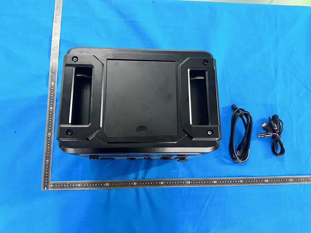
2BDCB-P2400PRO
Aug 18, 2026Portable power station
Equipment Class
DTS - Digital Transmission System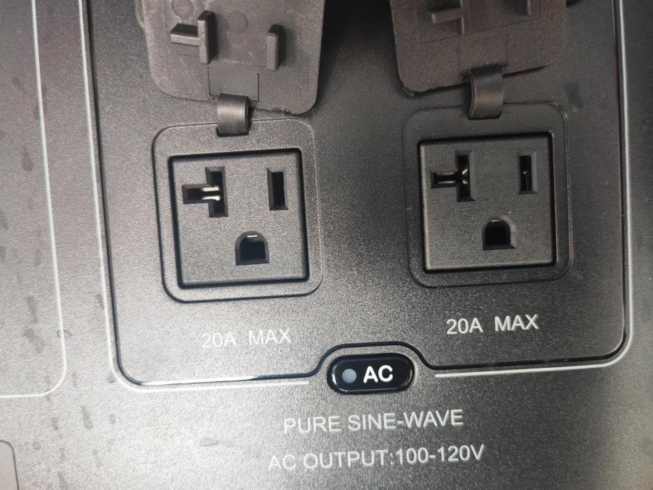
2BDCB--BP3000
Jun 11, 2026Portable power station
Equipment Class
DTS - Digital Transmission System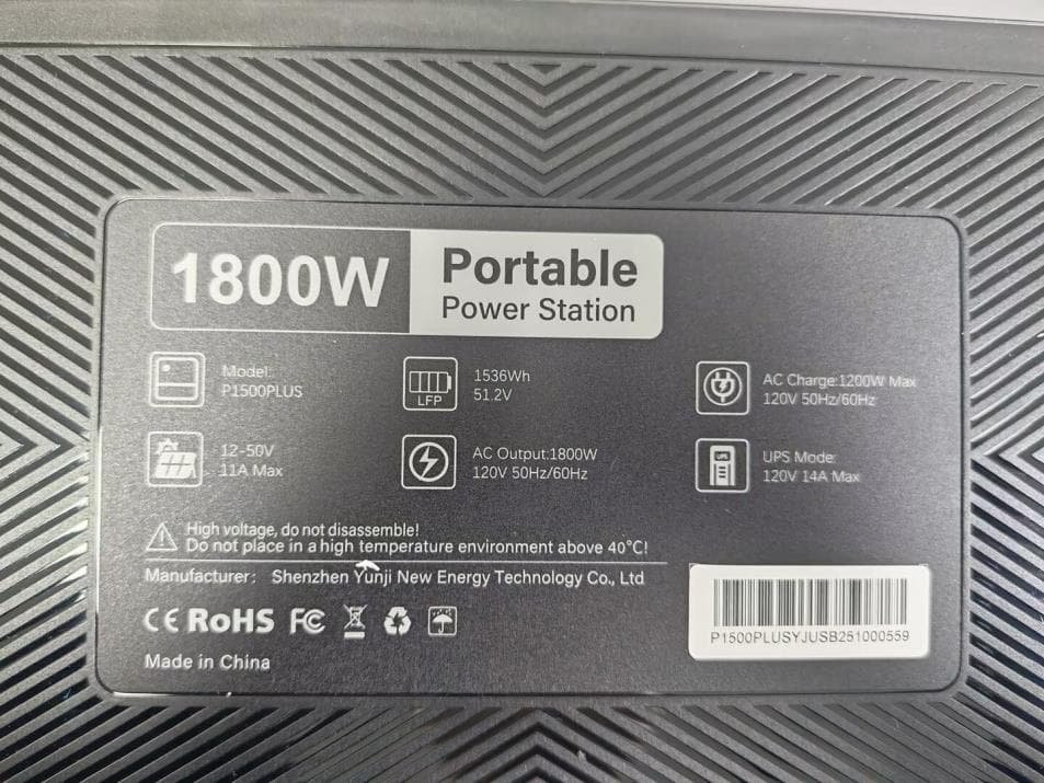
2BDCB--P1500PLUS
May 22, 2026Portable power station
Equipment Class
DTS - Digital Transmission System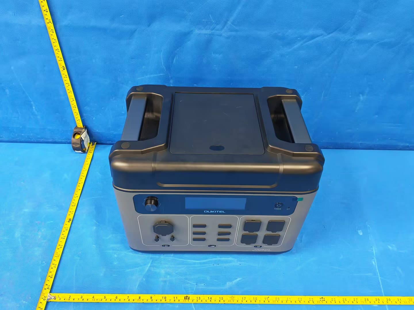
2BDCB-P2001PLUS
May 22, 2026Portable power station
Equipment Class
DTS - Digital Transmission System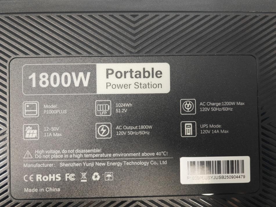
2BDCB--P1000PLUS
May 22, 2026Portable power station
Equipment Class
DTS - Digital Transmission System