2BDCI-JUD-AT01JUD AIR TRACKER
E&C SMART LINK TECHNOLOGY CO., LTD.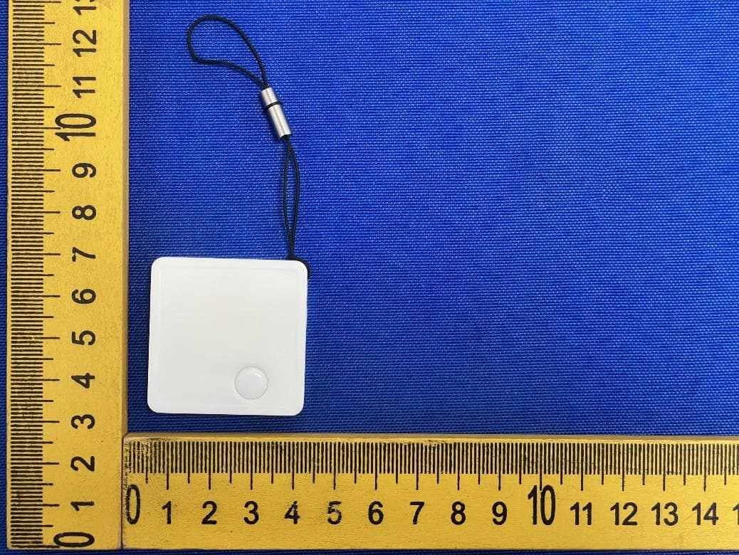
Click to zoom
Application Details
- Equipment Class
- DTS - Digital Transmission System
- Date of Grant
- Nov 07, 2023
- Application Purpose
- Original Equipment
- Date of Application
- Nov 06, 2023
- Equipment Note
- JUD AIR TRACKER
- Frequency Range
- 2402.00000000 - 2480.00000000
- Country
- Thailand
Documents & Files
Document Text
Text extracted from the exhibit documents filed with the FCC. Open a document above to read the original.
Users Manual
FAQ 1. ¿Cuándo el dispositivo puede ser localizado por otro iPhone? Cuando el dispositivo se desconecta del iPhone del propietario durante aproximadamente 15 minutos, otros iPhones pueden comenzar a ubicar el dispositivo y el propietario puede comenzar a obtener la ubicación del dispositivo. 2.¿Cómo confirmar si el dispositivo se ha encendido? Haga doble clic en el botón del dispositivo, el dispositivo emitirá un pitido y la luz parpadeará tres veces, lo que indica que el dispositivo está funcionando. Si el dispositivo no suena, el dispositivo está apagado. Mantenga presionado el botón durante cinco segundos para encender. 3.Cómo reemplazar la batería: 1)Abra el dispositivo desde el lado de la muesca 2)Reemplace la batería por una nueva. (Polo positivo hacia arriba) 3)Ensamble el dispositivo y mantenga presionado el botón durante 5 segundos para reiniciarlo. Instrucciones para el botón del dispositivo 1. Encendido: Después de instalar la batería, mantenga presionado el botón durante cinco segundos, el dispositivo emite un pitido, la luz parpadea tres veces y el dispositivo se enciende. 2. Confirmación del estado del dispositivo: Haga doble clic en el botón del dispositivo, el dispositivo emite un pitido y la luz parpadea tres veces, lo que indica que el dispositivo está funcionando. Si el dispositivo no suena, el dispositivo está apagado. Mantenga presionado el botón durante cinco segundos para encender. 3. El dispositivo vuelve a entrar en el estado de emparejamiento: Después de quitar el dispositivo en la aplicación, el dispositivo emitirá un pitido y la luz parpadeará seis veces, no se apagará y estará en el modo de emparejamiento. Si no se vuelve a emparejar en 10 minutos, el dispositivo dejará el estado de emparejamiento. Si desea emparejar un dispositivo en este momento, debe hacer clic en el botón del dispositivo una vez, el dispositivo emitirá un pitido y la luz parpadeará una vez. En este momento, el dispositivo ingresa al estado de emparejamiento y se puede emparejar con la aplicación nuevamente. 4. Restaure la configuración de fábrica del dispositivo: Primero, en la aplicación Buscar, elimine el dispositivo. Después de encender el dispositivo, haga doble clic en el botón del dispositivo, el dispositivo emite un pitido, presione inmediatamente y mantenga presionado el botón del dispositivo durante unos 8 segundos, hasta que el dispositivo emita el segundo pitido, y la luz indicadora parpadea tres veces y suelta el botón. El restablecimiento de fábrica está completo y el dispositivo se puede emparejar con la nueva cuenta. 5.Apague: Cuando el dispositivo esté encendido, presione el botón del dispositivo 5 veces de forma continua en 2 segundos, el dispositivo emitirá un pitido y la luz indicadora parpadeará tres veces, y el dispositivo entrará en el estado de apagado. Funciones principales 1. Haga sonar el dispositivo: haga clic en Reproducir sonido y el dispositivo emitirá un pitido para que pueda encontrar el elemento fácilmente. 2. La red Buscar ayuda a localizar: cuando el dispositivo está lejos, no se puede conectar en la aplicación. Puede elegir Modo Perdido, Habilitar. Ingrese el número de teléfono móvil, etc. Después de que el dispositivo se desconecte del iPhone del propietario durante aproximada- mente 15 minutos, y si hay un iPhone cerca del dispositivo perdido, la aplicación Buscar del propietario puede recibir notificaciones y mostrar la ubicación más reciente. Consejos Importantes Al vincular un dispositivo con la aplicación Buscar,el teléfono se vinculará con el servidor de Apple. El emparejamiento puede fallar debido a problemas de red. Se recomiendan las siguientes acciones: 1. Cambiar la red móvil, como cambiar entre WIFI y red móvil 2. Restaure la configuración de fábrica del dispositivo: después de encender el dispositivo, haga doble clic en el botón del dispositivo, el dispositivo emite un pitido, presione inmediatamente y mantenga presionado el botón del dispositivo durante unos 8 segundos, hasta que el dispositivo emita el segundo pitido, y la luz indicadora parpadea y suelta el botón. El restablecimiento de fábrica está completo. (Nota: después de presionar prolongadamente el botón del dispositivo durante 2 segundos, el dispositivo sonará "tick, tick, tick" y la luz indicadora cerca del botón parpadeará. No lo suelte. Continúe presionando y manteniendo presionado el botón hasta que el dispositivo emita una música por segunda vez, y la luz indicadora parpadea. Suelte el botón). 3. Vuelva a emparejar con la aplicación Buscar Instrucciones rápidas 1. Encienda el dispositivo: mantenga presionado el botón durante 5 segundos, el dispositivo emitirá un pitido y se encenderá. 2. Abra la aplicación que viene con el sistema iOS: Buscar. 3. Elige: Objetos. 4. Elige: Añadir objeto nuevo. 5. Elige: Añadir otro objeto. 6. Elige: El dispositivo: F11X. 7. Nombra el dispositivo, elige el emoji y completa el emparejamiento. 8. Habilite el modo perdido e ingrese el número de teléfono móvil de contacto, etc. Luego, La red Buscar funcionará. . 9. Ahora, puede usar el dispositivo. 10. Eliminar el objeto: para eliminar el objeto en la aplicación, puede seleccionar Eliminar objeto. Nota: Después de quitar el dispositivo en la aplicación, el dispositivo emitirá un pitido y la luz parpadeará seis veces, no se apagará y estará en el modo de emparejamiento. Si no se vuelve a emparejar en 10 minutos, el dispositivo dejará el estado de emparejamiento. Si desea emparejar un objeto en este momento, debe hacer clic en el botón del objeto una vez, el objeto emitirá un pitido y la luz parpadeará una vez. En este momento, el objeto ingresa al estado de emparejamiento y se puede emparejar con la aplicación nuevamente.
Attestation Statements
E&C SMART LINK TECHNOLOGY CO., LTD. Federal Communications Commission Authorization and Evaluation Division 7435 Oakland Mills Road Columbia, MD 21046 USA Date: 2023-11-01 FCC ID: 2BDCI-JUD-AT01 Ref. #1: Attestation Statements Part 2.911(d)(5)(i) Filing E&C SMART LINK TECHNOLOGY CO., LTD. certifies that the equipment for which authorization is sought is not “covered” equipment prohibited from receiving an equipment authorization pursuant to section 2.903 of the FCC rules. Ref. #2: Attestation Statements Part 2.911(d)(5)(ii) Filing E&C SMART LINK TECHNOLOGY CO., LTD. certifies that, as of the date of the filing of the application, the applicant is not identified on the Covered List as an entity producing “covered” equipment. Applicant: E&C SMART LINK TECHNOLOGY CO., LTD. Address: 209/11, Mu 2, Phraek Sa Mai Sub-district, Mueang Samut Prakan District, Samut Prakan Province, Thailand Contact Person: Jeffrey Dou Tel.: +86 13691760066 Email: [email protected] Sincerely, Signature:
Attestation Statements
1/1 TO: Office Feder 7435 Colum US A Com p FRN:0 Conta Addre Telep Email EIN:9 This l a loca The U outlin § 2.9 Appl Com p Produ FRN:0 Grant FCC I Conta Addre Praka Telep Email The A Equip This Date Appl Title Signa US Age e of Enginee ral Commun 5 Oakland Mi mbia, MD 21 Agent for Se pany Name: 0033489683 act Name: Da ess: 1312 17 phone No: (9 l:market@clf 98-1720547 letter is to co al representa US Agent fo ned in the FC 11. icant: pany name:E uct Descriptio 0034405282 tee code: 2B ID:2BDCI-JU act Name:Jef ess: 209/11, an Province, phone No: +8 l:Rd03@ecpl Applicant is pment Autho A greement e: 2023/11/ icant’s Nam :Project Ma ature ent for Se ering Techno ications Com lls Road 1046 ervice of Pr CLF Import a avid chen 7th Street #6 949) 254-256 fimportexpor onfirm that t ative on beha r Service of CC Equipmen E&C SMART L on: JUD AIR BDCI D-AT01 ffrey Dou Mu 2, Phra e Thailand 86 13691760 ink.com aware of a rization Pro g t is valid un /07 me:Jeffrey D anager ervice of P ology mmission rocess: and Export L 692,Denver 65 rt.com the US Agent alf ofE&C SM Process is a nt Authorizat LINK TECHN TRACKER ek Sa Mai Su 0066 nd a grees to gram, Report ntil (Perman Dou Process L Limited r, CO 80202, t for Service MART LINK TE aware of and tion Program OLOGY CO., b-district, M u o comply w t and Order F nently valid US Ag Title: Signa LETTER OF United State of Process a ECHNOLOGY d agrees to c , Report and LTD. ueang Samu ith the req u FCC 22-84, a d). gent for Se Manager ature F ATTEST es accepts resp Y CO., LTD.. comply with d Order FCC t Prakan Dis t uirements ou and clause § rvice of Pr o TATION onsibility to the require 22-84, and c trict, Samut utlined in the 2.911. ocess’s Nam act as ments clause e FCC me:
Cover Letter(s)
2.4 GHz Inverted F Antenna 1 Introduction This PCB antenna Max imum gain is measured o be +3.3 dB Manufacturer:SHZHEN HEXINGSHENG SMART LINK TECHNOLOGY CO., LTD. Addres s:2F, Building 7, Huaxing Industrial Park, Langqin Road. Dalang Street, Longhua District, Shenzhen City, China Page 1 of 11 2 Description of the Inverted F Antenna Design Since the impedance of the Inverted F Antenna is matched directly to 50 ohm no external matching components are needed. 2.1 Implementation of the Inverted F Antenna It is important to make an exact copy of the antenna dimensions to obtain optimum performance. The easiest approach to implement the antenna in a PCB CAD tool is to import the antenna layout from either a gerber or DXF file. Such files are included in CC2430DB reference design [1]. The gerber file is called “Inverted_F_Antenna.spl” and the DXF file is called “Inverted_F_Antenna.dxf”. If the antenna is implemented on a PCB that is wider than the antenna it is important to avoid placing components or having a ground plane close to the end points of the antenna. If the CAD tool being used doesn’t support import of gerber or DXF files, Figure 1 and Table 1 can be used. Figure 1. IFA Dimensions H1 5.70 mm H2 3.5 mm W1 1.21 mm Table 1. IFA Dimensions Since there is no ground plane beneath the antenna, PCB thickness will have little effect on the performance. The results presented in this design note are based on an antenna implemented on a PCB with 1 mm thickness. Page 2 of 11 H2 L1 3 Results All results presented in this chapter are based on measurements performed with CC2430DB [1]. 3 .1 Radiation Pattern Figure 2 shows how to relate all the radiation patterns to the orientation of the antenna. The radiation patterns were measured with CC2430 programmed to 0 dBm output power. XY plane XZ plane YZ plane Figure 2. How to Relate the Antenna to the Radiation Patterns Page 3 of 11 Figure 3. XY Plane Vertical Polarization Page 4 of 11 Figure 4. XY Plane Horizontal Polarization Page 5 of 11 Figure 5. XZ Plane Vertical Polarization Page 6 of 11 Figure 6. XZ Plane Horizontal Polarization Page 7 of 11 Figure 7. YZ Plane Vertical Polarization Page 8 of 11 Figure 8. YZ Plane Horizontal Polarization Page 9 of 11 4.2 Reflection Figure 9. Measured Reflection at the Feed Point of the Antenna Figure 9 show that the IFA ensures less than 10 % reflection of the available power for a bandwidth of more than 300 MHz. A large bandwidth makes the antenna less sensitive to detuning due to plastic encapsulation or other objects in the vicinity of the antenna. 4.3 Bandwidth Another way of measuring the bandwidth after the antenna is implemented on a PCB and connected to a transmitter is to write test software that steps a carrier across the frequency band of interest. By using the “Max hold” function on a spectrum analyzer the variation in output power across frequency can easily be measured. Figure 10 shows how the output power varies on the IFA when the PCB is horizontally oriented and the receiving antenna has horizontal polarization. This measurement was not performed in an anechoic chamber thus the graph shows only the relative variation for the given frequency band. Page 10 of 11 Bandwidth IFA 2.4 2.4835 -60 -50 -40 -30 -20 -10 0 2.22.32.42.52.62.72.8 Frequency [GHz] Relative output power [dB] Output pow er Low er band edge Upper band edge Figure 10. Bandwidth of IFA 5 Conclusion The PCB antenna introduc ed in this document performs well at all frequencies in the 2.4GHz ISM frequency band. The antenna has an omnidirectional radiation pattern on the PCB plane. Regardless of the operating frequency and position of the antenna, these characteristics will ensure stable performance. Table 2 lists the most important charac teristics of the inverted F antenna. Gain in XY Plane 1.1 dB Gain in XZ Plane 3.3 dB Gain in YZ Plane 1.6 dB Reflection < -15 dB Antenna Size 5.7mmx 3.5 mm x1.21mm Table 2. Summery of the Properties of the IFA Page 11 of 11
Cover Letter(s)
E&C SMART LINK TECHNOLOGY CO., LTD. Office of Engineering Technology Federal Communications Commission 7435 Oakland Mills Road Columbia, MD 21046 USA Date: November 1, 2023 Subject; Request for Confidentiality FCC ID: 2BDCI-JUD-AT01 To Whom It May Concern, Pursuant to the provisions of the Commission’s rules Title 47 Sections §0.457 and §0.459, we are requesting the Commission to withhold the following attachment(s) as confidential documents from public disclosure indefinitely. These documents contain detailed system and equipment descriptions and are considered as proprietary information in operation of the equipment. The public disclosure of these documents might be harmful to our company and would give competitors an unfair advantage in the market. Schematic Diagram Block Diagram Parts List Operational Description Tune-up Procedure Software Security Requirements for UNII devices In additional to above mentioned documents, in order to comply with the marketing regulations in Title 47 CFR §2.803 and the importation rules in Title 47 CFR §2.1204, while ensuring that business sensitive information remains confidential until the actual marketing of newly authorized devices, we request Short Term Confidentiality of the following attachment(s); External Photos Test Setup Photos Internal Photos User Manual For 45 days, pursuant to Public Notice DA 04-1705. OR For 180 days pursuant to KDB 726920 D01. It is our understanding that all measurement test reports, FCC ID label format and correspondence during the certification review process cannot be granted as confidential documents and this information will be available for public review once the grant of equipment authorization is issued. Sincerely, Signature: Name: Jeffrey Dou Title: Project Engineer
Cover Letter(s)
Effective Date: April 2, 2020 QSF 7.6.4-8 – Agent Authorization Letter Template Page 1 of 1 Revision Date: Revision: 0 E&C SMART LINK TECHNOLOGY CO., LTD. Date:Nov. 01, 2023 Product Model Number: JUD-AT01 FCC ID:2BDCI-JUD-AT01 To whom it may concern, Re: Product Certification Representative Authorization Letter We authorize QAI Laboratories Ltd. 3980 North Fraser Way, Burnaby B.C. Canada V5J 5K5 to act on our behalf on all matters concerning the above named equipment. This shall include the following: Testing Approval applications and procedures We declare that ORGANIZATION. is allowed to forward all information related to the approval project to the applied certification body and to the notification entities and to discuss any issues concerning the approval application. Any and all acts carried out by ORGANIZATION. on our behalf shall have the same effect as acts of our own. By: Contact Listed on FCC Wesbite Title: Project Engineer Email: [email protected] Telephone: +86 13691760066 On behalf of: E&C SMART LINK TECHNOLOGY CO., LTD.
External Photos
Ext Photos Photo 1 Photo 2 Photo 3 Photo 4 Photo 5 Photo 6
ID Label/Location Info
Label and Label Location Label: Label Location:
Internal Photos
Int Photos Photo 1 Photo 2 Photo 3 Photo 4 Photo 5 Photo 6 BT ANT Photo 7 Photo 8
RF Exposure Info
- Page 1 of 9 - Report No.: HB20231011001E-02 Add:Room 102, 201, Building 2, Yuanwanggu RFID Industrial Park, Tongguan Road, Tianliao Community, Yutang Street, Guangming District, Shenzhen,China Tel: (86-755) 29989321 Fax: (86-755) 29985110 Web:www.sz-hongbiao.com RF EXPOSURE Test Report Product: JUD AIR TRACKER Trade Mark: JUD Model Number: JUD-AT01 FCC ID: 2BDCI-JUD-AT01 Prepared for E&C SMART LINK TECHNOLOGY CO., LTD. 209/11, Mu 2, Phraek Sa Mai Sub-district, Mueang Samut Prakan District, Samut Prakan Province, Thailand Prepared by Shenzhen HongBiao Certification& Testing Co., Ltd Room 102, 201, Building 2, Yuanwanggu RFID Industrial Park, Tongguan Road, Tianliao Community, Yutang Street, Guangming District, Shenzhen, China Tel.: +86-755-2998 9321 Fax.: +86-755-2998 5110 Website: http://www.sz-hongbiao.com - Page 2 of 9 - Report No.: HB20231011001E-02 Add:Room 102, 201, Building 2, Yuanwanggu RFID Industrial Park, Tongguan Road, Tianliao Community, Yutang Street, Guangming District, Shenzhen,China Tel: (86-755) 29989321 Fax: (86-755) 29985110 Web:www.sz-hongbiao.com Table of Contents 1 GENERAL DESCRIPTION ..................................................................................................................................... 5 1.1 DESCRIPTION OF EUT ................................................................................................................................................ 5 1.2 TEST MODE .............................................................................................................................................................. 5 1.3 TEST SETUP .............................................................................................................................................................. 5 1.4 ANCILLARY EQUIPMENT .............................................................................................................................................. 5 2 TEST FACILITIES AND ACCREDITATIONS .............................................................................................................. 6 2.1 TEST LABORATORY ..................................................................................................................................................... 6 2.2 ENVIRONMENTAL CONDITIONS ..................................................................................................................................... 6 2.3 MEASUREMENT UNCERTAINTY ..................................................................................................................................... 6 2.4 TEST SOFTWARE ........................................................................................................................................................ 6 3 LIST OF TEST EQUIPMENT .................................................................................................................................. 7 4 RF EXPOSURE..................................................................................................................................................... 8 4.1 STANDALONE SAR TEST EXCLUSION CONSIDERATIONS........................................................................................................ 8 4.1.1. Limit ............................................................................................................................................................ 8 4.1.2. Test Procedures ........................................................................................................................................... 8 4.1.3. Test Result ................................................................................................................................................... 9 - Page 3 of 9 - Report No.: HB20231011001E-02 Add:Room 102, 201, Building 2, Yuanwanggu RFID Industrial Park, Tongguan Road, Tianliao Community, Yutang Street, Guangming District, Shenzhen,China Tel: (86-755) 29989321 Fax: (86-755) 29985110 Web:www.sz-hongbiao.com TEST RESULT CERTIFICATION Applicant’s Name ................. : E&C SMART LINK TECHNOLOGY CO., LTD. Address ................................. : 209/11, Mu 2, Phraek Sa Mai Sub-district, Mueang Samut Prakan District, Samut Prakan Province, Thailand Manufacturer's Name .......... : E&C SMART LINK TECHNOLOGY CO., LTD. Address ................................. : 209/11, Mu 2, Phraek Sa Mai Sub-district, Mueang Samut Prakan District, Samut Prakan Province, Thailand Product description Product name ........................ : JUD AIR TRACKER Model Number ....................... : JUD-AT01 Standards ............................. : N/A Test procedure ..................... : KDB 447498 D01 v06 This device described above has been tested by Shenzhen HongBiao Certification& Testing Co., Ltd and the test results show that the equipment under test (EUT) is in compliance with the EMC requirements. And it is applicable only to the tested sample identified in the report. Date of Test ........................................... : Date (s) of performance of tests ............. : Oct. 11. 2023~Nov. 01. 2023 Test Result .............................................. : Pass Testing Engineer : ( Z o e Su) Technical Manager : ( G a r y Lu) Authorized Signatory : (L e o S u) - Page 4 of 9 - Report No.: HB20231011001E-02 Add:Room 102, 201, Building 2, Yuanwanggu RFID Industrial Park, Tongguan Road, Tianliao Community, Yutang Street, Guangming District, Shenzhen,China Tel: (86-755) 29989321 Fax: (86-755) 29985110 Web:www.sz-hongbiao.com Revision History Revised No. Date of Issue Description 01 Nov. 01. 2023 Original - Page 5 of 9 - Report No.: HB20231011001E-02 Add:Room 102, 201, Building 2, Yuanwanggu RFID Industrial Park, Tongguan Road, Tianliao Community, Yutang Street, Guangming District, Shenzhen,China Tel: (86-755) 29989321 Fax: (86-755) 29985110 Web:www.sz-hongbiao.com 1 General Description 1.1 Description of EUT Product name: JUD AIR TRACKER Model name: JUD-AT0…
Text truncated - open the document above for the full version.
Test Report
- Page 1 of 41 - Report No.: HB20231011001E-01 Add:Room 102, 201, Building 2, Yuanwanggu RFID Industrial Park, Tongguan Road, Tianliao Community, Yutang Street, Guangming District, Shenzhen,China Tel: (86-755) 29989321 Fax: (86-755) 29985110 Web:www.sz-hongbiao.com Test Report Product: JUD AIR TRACKER Trade Mark: JUD Model Number: JUD-AT01 FCC ID: 2BDCI-JUD-AT01 Prepared for E&C SMART LINK TECHNOLOGY CO., LTD. 209/11, Mu 2, Phraek Sa Mai Sub-district, Mueang Samut Prakan District, Samut Prakan Province, Thailand Prepared by Shenzhen HongBiao Certification& Testing Co., Ltd Room 102, 201, Building 2, Yuanwanggu RFID Industrial Park, Tongguan Road, Tianliao Community, Yutang Street, Guangming District, Shenzhen, China Tel.: +86-755-2998 9321 Fax.: +86-755-2998 5110 Website: http://www.sz-hongbiao.com - Page 2 of 41 - Report No.: HB20231011001E-01 Add:Room 102, 201, Building 2, Yuanwanggu RFID Industrial Park, Tongguan Road, Tianliao Community, Yutang Street, Guangming District, Shenzhen,China Tel: (86-755) 29989321 Fax: (86-755) 29985110 Web:www.sz-hongbiao.com Table of Contents 1 GENERAL DESCRIPTION ..................................................................................................................................... 6 1.1 DESCRIPTION OF EUT ................................................................................................................................................ 6 1.2 TEST MODE .............................................................................................................................................................. 6 1.3 OPERATION CHANNEL LIST ........................................................................................................................................... 7 1.4 TEST SETUP .............................................................................................................................................................. 7 1.5 ANCILLARY EQUIPMENT .............................................................................................................................................. 7 2 SUMMARY OF TEST RESULT ............................................................................................................................... 8 3 TEST FACILITIES AND ACCREDITATIONS .............................................................................................................. 9 3.1 TEST LABORATORY ..................................................................................................................................................... 9 3.2 ENVIRONMENTAL CONDITIONS ..................................................................................................................................... 9 3.3 MEASUREMENT UNCERTAINTY ..................................................................................................................................... 9 3.4 TEST SOFTWARE ........................................................................................................................................................ 9 4 LIST OF TEST EQUIPMENT .................................................................................................................................10 5 TEST ITEM AND RESULTS ...................................................................................................................................12 5.1 ANTENNA REQUIREMENT .......................................................................................................................................... 12 5.1.1 Standard Requirement ............................................................................................................................. 12 5.1.2 Test Result ................................................................................................................................................. 12 5.2 CONDUCTED EMISSION ............................................................................................................................................. 13 5.2.1 Limits ........................................................................................................................................................ 13 5.2.2 Test Procedures ......................................................................................................................................... 13 5.2.3 Test Setup .................................................................................................................................................. 14 5.2.4 Test Result ................................................................................................................................................. 14 5.3 RADIATED EMISSION ................................................................................................................................................ 15 5.3.1 Limits ........................................................................................................................................................ 15 5.3.2 Test Procedures ......................................................................................................................................... 15 5.3.3 Test Setup .................................................................................................................................................. 15 5.3.4 Test Result ................................................................................................................................................. 16 5.3.5 Band Edge - Radiated ............................................................................................................................... 20 5.3.6 Spurious emission in restricted band 1GHz-25GHz .................................................................................. 21 5.4 PEAK OUTPUT POWER ....................................................................................................................…
Text truncated - open the document above for the full version.
Test Setup Photos
- Page 1 of 1 - Test Setup Photos Radiated Emission Below 1GHz Radiated Emission Above 1GHz
Contact Information
Applicant
Jeffrey Dou
Technical Contact
Test Firm
Shenzhen HongBiao Certification& Testing Co., LtdLeo Su
[email protected]13265750412
Technical Specifications
| # | Rule Parts | Frequency Range | Power Output |
|---|---|---|---|
| 1 | 15C | 2.40 GHz - 2.48 GHz | 372.00 µW |
Other Applications from E&C SMART LINK TECHNOLOGY CO., LTD.
2BDCI-RS-BTS3BK
Dec 12, 2025Karaoke speaker with wireless microphone
Equipment Class
DSS - Part 15 Spread Spectrum Transmitter2BDCI-RPA-BTS10BK
Dec 02, 2025Splash Shower Speaker
Equipment Class
DSS - Part 15 Spread Spectrum Transmitter