2BDLN-STPMIDNATelematic Device
Continental Engineering Services GmbH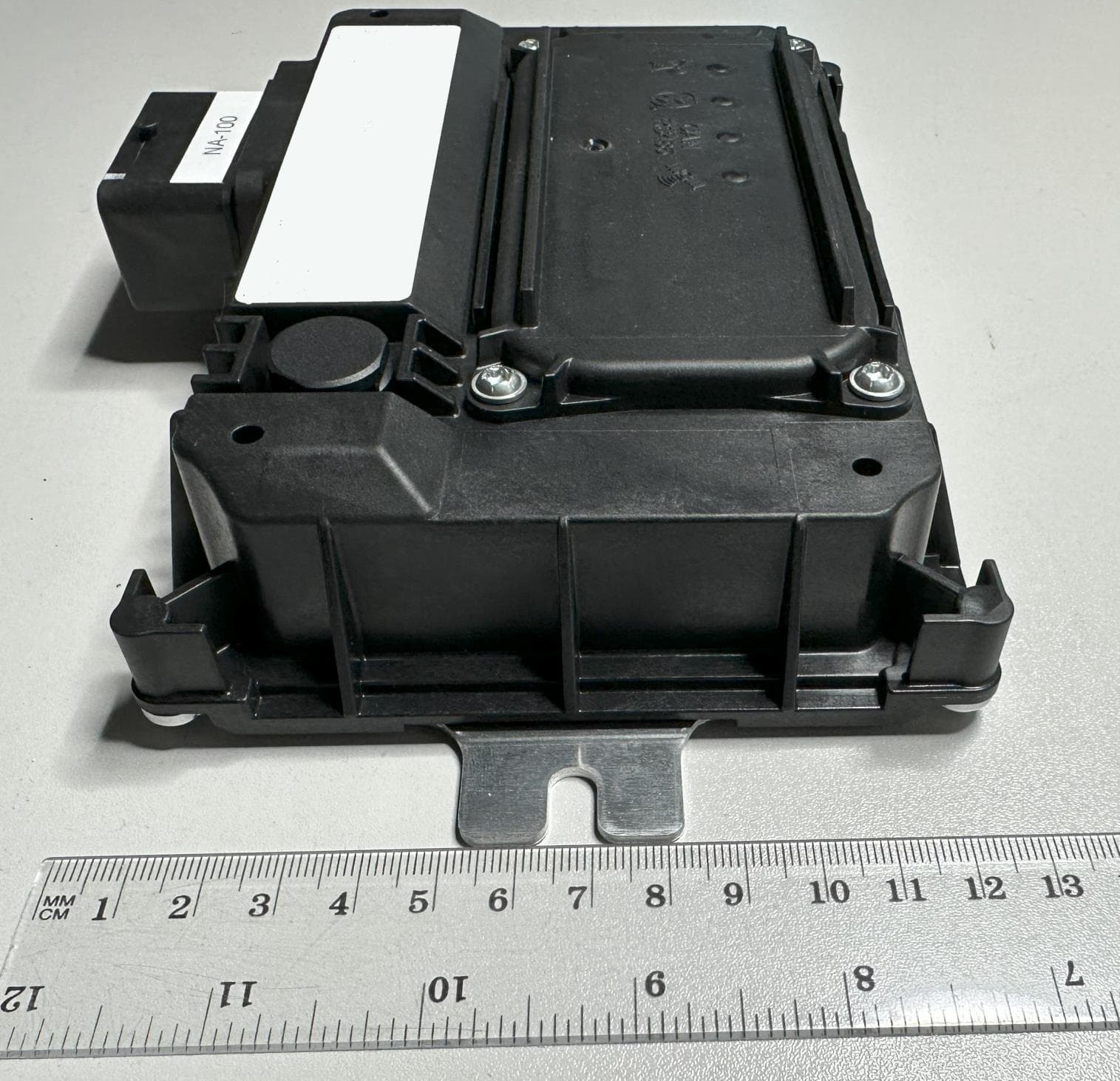
Click to zoom
Application Details
- Equipment Class
- CXX - Communications Rcvr for use w/ licensed Tx and CBs
- Date of Grant
- Mar 12, 2024
- Application Purpose
- Original Equipment
- Date of Application
- Mar 12, 2024
- Equipment Note
- Telematic Device
- Frequency Range
- 746.00000000 - 756.00000000
- Country
- Germany
Documents & Files
Document Text
Text extracted from the exhibit documents filed with the FCC. Open a document above to read the original.
Users Manual
User Manual © Continental Engineering Services GmbH – Strictly Confidential 06.03.2024/Page 1 Internal Continental Engineering Services GmbH User Manual Honda 4G TCU Document name: Honda4G_User_Manual.docx Authors: [email protected] Date: 06.03.2024 Status: Draft Proposed Released Version: 1.4 Reviewed: Szolc Tomasz Date: 06.03.2024 Released: Mrowietz Tobias Date: 06.03.2024 User Manual © Continental Engineering Services GmbH – Strictly Confidential 06.03.2024/Page 2 Internal Document Revision History Revision Date Change Author Change Summary 0.1 22.11.2023 Tomasz Szolc Initial bring up of the document 1.0 23.11.2023 Tobias Mrowietz Update table of content Update FCC-ID 1.1 09.02.2024 Tobias Mrowietz Update FCC-ID chapter 1.2 19.02.2024 Tobias Mrowietz Remove NAD FCC ID reference 1.3 19.02.2024 Tobias Mrowietz Add Part 15 user notice 1.4 06.03.2024 Tobias Mrowietz Add separation of 20 cm notice User Manual © Continental Engineering Services GmbH – Strictly Confidential 06.03.2024/Page 3 Internal Content INTRODUCTION ................................................................................................................. 4 1.1. Document scope .................................................................................................................................................. 4 2. HARDWARE OVERVIEW ............................................................................................ 5 2.1. TCU connection .................................................................................................................................................. 5 2.2. Pinout overview .................................................................................................................................................. 6 2.3. LED behavior ...................................................................................................................................................... 7 3. MOUNTING POSITION OF THE TCU .......................................................................... 8 4. 3 RD PARTY CODE AND LICENSING .......................................................................... 9 4.1. FOSS Components ............................................................................................................................................. 9 4.1.1. MQTT Library ................................................................................................................................................. 9 4.1.2. Logging framework ......................................................................................................................................... 9 4.1.3. JSON library .................................................................................................................................................... 9 4.1.4. AWS IoT Core SDK ........................................................................................................................................ 9 4.2. Proprietary Components ................................................................................................................................... 9 5. CERTIFICATION ........................................................................................................ 10 5.1. Japan ................................................................................................................................................................. 10 5.2. USA FCC ........................................................................................................................................................... 10 COPYRIGHT ..................................................................................................................... 12 User Manual © Continental Engineering Services GmbH – Strictly Confidential 06.03.2024/Page 4 Internal Introduction 1.1. Document scope This document describes the Honda 4G TCU device. The description contains a step-by- step connection guide as well as a description of connections. A detailed description of LED behavior and mounting instructions are provided to ensure correct usage of the device. User Manual © Continental Engineering Services GmbH – Strictly Confidential 06.03.2024/Page 5 Internal 2. Hardware overview 2.1. TCU connection Connecting the harness to the TCU. For powering up: ➔ Connect KL31 to ground of power supply ➔ Connect KL30 to 12V power supply ➔ Connect KL15 to KL30 (Ignition Pin) ➔ Connect USB to the computer for debugging purposes User Manual © Continental Engineering Services GmbH – Strictly Confidential 06.03.2024/Page 6 Internal 2.2. Pinout overview Relevant PINs Pin number Signal type M2 KL31 M1 KL30 L1 KL15 B1 CAN1 L A1 CAN1 H E1 BRR DM F1 BRR DP H1 USB DP J1 USB DM K1 GND K2 WR Disable User Manual © Continental Engineering Services GmbH – Strictly Confidential 06.03.2024/Page 7 Internal 2.3. LED behavior The LEDs on the TCU are used to signal different information, depending on their state. General TCU state: • All LEDs on for 1 second = TCU is started • All LEDs on for approx. 10 seconds = TCU is going into suspend • All LEDs flicker (250 ms on, 250 ms off) = Configuration (config.json) missing or invalid (wrong format or values) Individual feature state: LED 1 (yellow) = LTE: • Off = LTE not connected • Blinking = Establishing LTE connection • On = LTE connected LED 2 (white) = Wi-Fi: • Off = Wi-Fi not connected • Blinking = Establishing Wi-Fi connection • On = Wi-Fi connected LED 3 (blue) = AWS: • Off = AWS not connected • Blinking = Establishing AWS connection • On = AWS connected LED 4 (orange) = GPS: • Off = no GPS fix • On = GPS fix User Manual © Continental Engineering Services GmbH – Strictly Confidential 06.03.2024/Page 8 Internal 3. Mounting position of the TCU To have a good signal reception consider the following points for mounting: - clear view to the sky - avoid metallized windshields - minimum 3 cm clearance on every side of the TCU - the…
Text truncated - open the document above for the full version.
Attestation Statements
1/1 Continental Engineering Services GmbH | Breitlacherstr. 94, 60489 Frankfurt am Main www.conti-engineering.com Sitz der Gesellschaft: Frankfurt am Main | Registergericht: Amtsgericht Frankfurt am Main HRB 76752 | USt-ID-Nr.: DE 215585768 Vorsitzender des Aufsichtsrats: Dr. Jochen Weisse Geschäftsführer: Jean-Michel Verdier, Waldemar Lissy Bankverbindung: Deutsche Bank AG, Nürnberg | BIC / SWIFT: DEUTDEMM760 | IBAN: DE30 7607 0012 0022 8650 00 Engineering Services Internal Continental Engineering Services GmbH Breitlacherstrasse 94 D-60489 Frankfurt a.M. Germany Federal Communication Commission Authorization and Evaluation Division 7435 Oakland Mills Road Columbia, MD 21046 USA 16.01.2024 Attestation Statement according to 2.911(d)(5)(i) and 2.911(d)(5)(ii) FCC ID: 2BDLN-STPMIDNA TO WHOM IT MAY CONCERN: Hereby we certify that the equipment for which authorization is sought is not “covered” equipment prohibited from receiving an equipment authorization pursuant to section 2.903 of the FCC rules. Further we certify that, as of the date of the filing of the application, Continental Engineering Services GmbH is not identified on the Covered List as an entity producing “covered” equipment. Sincerely, _______________ (signature & company stamp) Continental Engineering Services GmbH FRN 0034485417 Breitlacherstrasse 94 D-60489 Frankfurt a.M. Germany Tobias Eckl +49-911-21774-4526 [email protected]
Cover Letter(s)
1/1 Continental Engineering Services GmbH | Breitlacherstr. 94, 60489 Frankfurt am Main www.conti-engineering.com Sitz der Gesellschaft: Frankfurt am Main | Registergericht: Amtsgericht Frankfurt am Main HRB 76752 | USt-ID-Nr.: DE 215585768 Vorsitzender des Aufsichtsrats: Dr. Jochen Weisse Geschäftsführer: Jean-Michel Verdier, Waldemar Lissy Bankverbindung: Deutsche Bank AG, Nürnberg | BIC / SWIFT: DEUTDEMM760 | IBAN: DE30 7607 0012 0022 8650 00 Engineering Services Internal Continental Engineering Services GmbH Breitlacherstrasse 94 D-60489 Frankfurt a.M. Germany 16.01.2024 Authorization Letter TO WHOM IT MAY CONCERN: hereby we Continental Engineering Services GmbH declare that Mr Tobias Eckl (Continental Engineering Services GmbH) can sign in behalf of Tobias Mrowietz for this product STP-MID NA and FCC ID 2BDLN-STPMIDNA. Sincerely _______________ _______________ (signature & company stamp) (signature) Continental Engineering Services GmbH Continental Engineering Services GmbH FRN 0034485417 FRN 0034485417 Breitlacherstrasse 94 Breitlacherstrasse 94 D-60489 Frankfurt a.M. D-60489 Frankfurt a.M. Germany Germany Tobias Eckl Tobias Mrowietz +49-911-21774-4526 +49 151 52 67 61 88 [email protected] [email protected]
Cover Letter(s)
CONFIDENTIALITY REQUEST for Certification Service in USA Federal Communication Commission Equipment Authorization Division, Application Processing Branch 7435 Oakland Mills Road Columbia, MD 21048 <2023-11-22> TO WHOM IT MAY CONCERN Pursuant to Paragraphs §0.457 and 0.459 of the Commission’s Rules (47 C.F.R.) and Section §552(b) (4) of the Freedom of Information Act, we requests confidentiality for the following products: FCC ID 2BDLN-STPMIDNA Model name STP-MID NA For the product stated above, we request that the following information be held confidential; Exhibits Long-Term Confidentiality Short-Term Confidentiality External Photos Internal Photos Block Diagram Schematics Test Setup Photos User’s Manual Parts List Tune Up Operational Description The long-term confidentiality exhibits contain our trade secrets and proprietary information that could be of benefit to our competitors. The short-term confidentiality on the basis of ensuring that business sensitive information remains confidential until the actual marketing of our new device, which is planned for 01.03.2024. If you have any questions, please feel free to contact me at the address shown below. Sincerely, (Signed) Name / Title: Tobais Mrowietz – technical Project Leader Company: Continental Engineering Services GmbH Address: Nordostpark 30, 90411 Nuremberg Phone: +49 151 52 67 61 88 E-Mail: [email protected]
External Photos
The test results relate only to the individual items which have been tested. This report shall not be reproduced in parts without the written approval of the testing laboratory © Copyright: All rights reserved by cetecom advanced GmbH Annex 3: External photographs 23-1-0043901T010a-A3 Number of pages: 3 Date of Report: 2024-Feb-16 Testing company: cetecom advanced GmbH Untertuerkheimer Str. 6-10 66117 Saarbruecken GERMANY Applicant: Continental Engineering Services GmbH Product: Telematic Device Model: STP-MID FCC ID: 2BDLN-STPMIDNA IC: N/A Testing has been carried out in accordance with: FCC Regulations Title 47 CFR, Chapter I, Subchapter A, Part 15 Subpart BUnintentional Radiators § 15.107 Conducted limits § 15.109 Radiated emission limits ISED-Regulations Radio Standards Specification RSS-Gen, Issue 5 General Requirements for Compliance of Radio Apparatus ICES-003, Issue 7 Information Technology Equipment (including Digital Apparatus) 23-1-0043901T010a-A3 TR23-1-0043901T010a-A3 2 / 3 1External photographs (EUT/DUT) Photograph 1 : EUT 1- Front side Photograph 2 : EUT 1- Connector side 23-1-0043901T010a-A3 TR23-1-0043901T010a-A3 3 / 3 Photograph 3 : CAB 1 End Of Annex 3
Test Report
Test Report 23-1-0043901T010a Number of pages: 17 Date of Report: 2024-Feb-16 Testing company: cetecom advanced GmbH Untertuerkheimer Str. 6-10 66117 Saarbruecken GERMANY Applicant: Continental Engineering Services GmbH Product: Telematic Device Model: STP-MID FCC ID: 2BDLN-STPMIDNA IC: N/A Testing has been carried out in accordance with: FCC Regulations Title 47 CFR, Chapter I, Subchapter A, Part 15 Subpart BUnintentional Radiators § 15.107 Conducted limits § 15.109 Radiated emission limits ISED-Regulations Radio Standards Specification RSS-Gen, Issue 5 General Requirements for Compliance of Radio Apparatus ICES-003, Issue 7 Information Technology Equipment (including Digital Apparatus) Test Results: ☒ The EUT complies with the requirements in respect of all parameters subject to the test. The test results relate only to devices specified in this document Signatures: Wolfgang Markus Hicham Laayouni Lab Manager Testing Manager Authorization of test report Responsible of test report Test Report 23-1-0043901T010a TR23-1-0043901T010a 2 / 17 Table of Contents Table of Annex .................................................................................................................................................................................. 3 1General information ................................................................................................................................................................ 4 1.1Disclaimer and Notes ......................................................................................................................................................... 4 1.2Attestation ......................................................................................................................................................................... 4 1.3Summary of Test Results ................................................................................................................................................... 5 1.4Summary of Test Methods ................................................................................................................................................ 5 2Administrative Data ................................................................................................................................................................. 6 2.1Identification of the Testing Laboratory ............................................................................................................................ 6 2.2General limits for environmental conditions ..................................................................................................................... 6 2.3Test Laboratories sub-contracted ...................................................................................................................................... 6 2.4Organizational Items ......................................................................................................................................................... 6 2.5Applicant’s details ............................................................................................................................................................. 6 2.6Manufacturer’s details ...................................................................................................................................................... 6 2.7Equipment under Test (EUT) ............................................................................................................................................. 7 2.8Untested Variant (VAR) ..................................................................................................................................................... 7 2.9Auxiliary Equipment (AE) ................................................................................................................................................... 7 2.10Connected cables (CAB)..................................................................................................................................................... 7 2.11Software (SW).................................................................................................................................................................... 7 2.12EUT set-ups ........................................................................................................................................................................ 7 2.13EUT operation modes ........................................................................................................................................................ 7 3Equipment under test (EUT) .................................................................................................................................................... 8 3.1General Data of Main EUT as Declared by Applicant ......................................................................................................... 8 3.2Modifications on Test sample ........................................................................................................................................... 8 4Measurements......................................................................................................................................................................... 9 4.1Radiated field strength emissions 30 MHz – 1 GHz ........................................................................................................... 9 4.2Radiated field strength emissions above 1 GHz .............................................................................................................. 12 5Results from external laboratory ........................................................................................................................................... 15 6Opinions and interpretations .......................................................................................................…
Text truncated - open the document above for the full version.
Test Report
The test results relate only to the individual items which have been tested. This report shall not be reproduced in parts without the written approval of the testing laboratory © Copyright: All rights reserved by cetecom advanced GmbH Annex 1: Measurement diagrams 23-1-0043901T010a-A1 Number of pages: 3 Date of Report: 2024-Feb-16 Testing company: cetecom advanced GmbH Untertuerkheimer Str. 6-10 66117 Saarbruecken GERMANY Applicant: Continental Engineering Services GmbH Product: Telematic Device Model: STP-MID FCC ID: 2BDLN-STPMIDNA IC: N/A Testing has been carried out in accordance with: FCC Regulations Title 47 CFR, Chapter I, Subchapter A, Part 15 Subpart BUnintentional Radiators § 15.107 Conducted limits § 15.109 Radiated emission limits ISED-Regulations Radio Standards Specification RSS-Gen, Issue 5 General Requirements for Compliance of Radio Apparatus ICES-003, Issue 7 Information Technology Equipment (including Digital Apparatus) 23-1-0043901T010a-A1 TR23-1-0043901T010a-A1 2 / 3 3.01 Common Information Date: 15.02.2024 Page 1 of 1 Test Description: Electric Fieldstrength Measurement Test Site & Location: Semi Anechoic Chamber 1 (SAC1); cetecom advanced GmbH, Essen Version of Testsoftware: EMC32 V10.60.20 Test Specification: FCC15.109, class B; RSS-Gen.: Issue 4 Operating Mode: GSM 850 IDLE Used Filter: none Measured side(s): front, right, rear, left Distance correction: no, measurement in 3m Distance with 3m Limits Environmental conditions: Humidity: 40 %rH; Temperature: 21 °C Operator: HLa EUT Information PMT Sample Nr.22-1-00439S02_C01 Full Spectrum 0 10 20 30 40 50 60 30M5060 80100M200300400500 8001G L e v e l i n d B μ V / m Frequency in Hz Full Spectrum Preview Result 1-PK+Critical_Freqs PK+ FCC15B_RSS_Gen_QPFinal_Result QPK FCC15B_RSS_Gen_QP 875,920000 MHz 36,989 dBμV/m 23-1-0043901T010a-A1 TR23-1-0043901T010a-A1 3 / 3 4.01 Common Information Test Description:Radiated Filed Strength Emission Test Site Location:CETECOM GmbH Essen Test Site:Fully Anechoic Room (FAR2) Test Standard:FCC Part 15.109, class B / RSS-Gen., Issue 4 Operating Mode:GSM850 IDLE Equipment Class: Class B Environmental Conditions:Humidity: 40 %rH; Temperature:21 °C Operator:Hla Setup:01 EUT Information PMT Sample Nr.22-1-00439S02_C01 End Of Annex 1 24 30 35 40 45 50 55 60 65 70 75 80 84 1G2G3G4G5G6G L e v e l i n d B μ V / m Frequency in Hz Full Spectrum FCC15_109_PK_Class_B FCC15_109_AV_Class_B
Test Setup Photos
The test results relate only to the individual items which have been tested. This report shall not be reproduced in parts without the written approval of the testing laboratory © Copyright: All rights reserved by cetecom advanced GmbH Annex 4: Test setup photographs 23-1-0043901T010a-A4 Number of pages: 4 Date of Report: 2024-Feb-16 Testing company: cetecom advanced GmbH Untertuerkheimer Str. 6-10 66117 Saarbruecken GERMANY Applicant: Continental Engineering Services GmbH Product: Telematic Device Model: STP-MID FCC ID: 2BDLN-STPMIDNA IC: N/A Testing has been carried out in accordance with: FCC Regulations Title 47 CFR, Chapter I, Subchapter A, Part 15 Subpart BUnintentional Radiators § 15.107 Conducted limits § 15.109 Radiated emission limits ISED-Regulations Radio Standards Specification RSS-Gen, Issue 5 General Requirements for Compliance of Radio Apparatus ICES-003, Issue 7 Information Technology Equipment (including Digital Apparatus) 23-1-0043901T010a-A4 TR23-1-0043901T010a-A4 2 / 4 1Test set up photographs (EUT/DUT) Photograph 1 : Measurements < 1GHz in SAC, overview Photograph 2 : Measurements < 1GHz in SAC, close up view 23-1-0043901T010a-A4 TR23-1-0043901T010a-A4 3 / 4 Photograph 3 : Measurements < 1GHz in SAC, rear side view Photograph 4 : Measurements > 1GHz in FAC, close up view 23-1-0043901T010a-A4 TR23-1-0043901T010a-A4 4 / 4 Photograph 5 : Measurements > 1GHz in FAC, overview End Of Annex 4
Contact Information
Applicant
Tobias Mrowietz
Test Firm
cetecom advanced GmbHGerald Schmidt
Technical Specifications
| # | Rule Parts | Frequency Range | Power Output |
|---|---|---|---|
| 3 | 15B | 746 MHz - 756 MHz | - |
Other Applications from Continental Engineering Services GmbH
2BDLN-NEBULATCU
Mar 06, 2026Telematics Device
Equipment Class
DTS - Digital Transmission System