2BDLQ-LFW2921-01Sensor Receiver
LEETEK LIFE CO.,LTD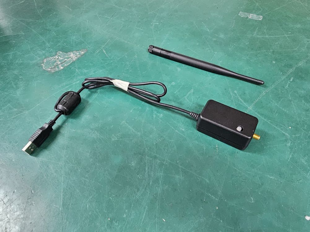
Click to zoom
Application Details
- Equipment Class
- DTS - Digital Transmission System
- Date of Grant
- Feb 20, 2024
- Application Purpose
- Original Equipment
- Date of Application
- Feb 20, 2024
- Equipment Note
- Sensor Receiver
- Frequency Range
- 902.50000000 - 927.50000000
- Company
- LEETEK LIFE CO.,LTD
- Country
- South Korea
Documents & Files
Document Text
Text extracted from the exhibit documents filed with the FCC. Open a document above to read the original.
Users Manual
21, Seounsandan-ro 6-gil, Gyeyang-gu, Incheon,Korea Tel. +82-32-556-9838 / Fax. +82-32-556-9838 www.leeteklife.com Unrivaled bowel sensor healthcare system that supports patients in maintaining self-esteem and hygiene Smart Healthcare System Bowel Sensor Operations Management System www.leeteklife.com 20172019201820202021 8.57M 13M 23 million 19 million 15 million 11 million 7 million 2022203020402050 17.22M 19 million The Aging Population in Transition The aging population over 65 is experiencing a notable increase. Challenges of Aged Care Facility Oversupply A need to differentiate services emerges An increasing number of aged care facilities Despite the growing elderly population services are experiencing low satisfaction levels 2 caused by exposure to humidity in diapers resulting from neglected bowel movements exacerbates the pain of patients in the room Colon bacillus, Dysentery, Staphylococcus aureus, etc The emotional burden of not being able to personally care for the patient weighs heavily on the guardians Skin rashes Unsanitary environment Bacteria in excrement Heightened anxiety for guardians Wearing a diaper poses a potential threat. to the health of patients, not only in terms of self-esteem. Nursing care workers responsible for numerous patients face a series of challenging and painful tasks when physically assessing the bowel condition of each patient. Providing the desired high-quality services to patients and their guardians is limited by the challenges of excessive labor costs and operational difficulties. The patient’s distress with a soiled diaper is difficult to comprehend, especially when they must wait for the diaper to be changed. The moment a patient is prescribed to wear a diaper their self-esteem may be adversely affected. 3 For patients dealing with dementia, urinary incontinence, severe conditions, and cognitive impairments related to defecation, our Smart Healthcare Bowel Sensor Operation System offers improved management. This extends support not only to the patients but also to the dedicated carers, who, always concerned about their patients’ conditions, indirectly bear the burden of suffering. Additionally, healthcare workers, responsible for the well-being of both patients and guardians, find enhanced care through our system. Our Smart Healthcare System is designed to provide comprehensive assistance. 4 1. What is the Bowel Sensor Operations Management System 2. What are the benefits of the system? 3. Detailed overview of the system’s processes 4. Product configuration for the system ... 6 ... 7 ... 10 ... 14 5 Experience an unrivaled bowel sensor healthcare system that not only supports patients in maintaining self-esteem and hygiene but also enhances overall patient management and hospital operations in real-time. 1. Counseling/Registration for Hospitalization 2. Hospitalization of Patient (with Attached Sensor) 3. Monitoring 4. Bowel Sensor Issuing Notifications for Bowel Movements 5. Data Delivery to Staff 6. Diaper Change (Health Care) 7. Patient Treatment and Care 8. Data Storage on Web Server 9. Consultation with Caregiver Processes of Smart Healthcare System What is the Bowel Sensor Operations Management System? 6 ・ Prompt assistance for patients, minimizing the occurrence of secondary diseases such as skin rashes, food poisoning, abdominal pain, diarrhea, bloody excrement, respiratory infections, bedsores, and more. ・ Elevated Patient’s Self-Esteem ・ Efficient Defecation Treatment Reducing Odor and Maintaining a Pleasant Environment ・ Increased User Satisfaction ・ Relieved Guardian Anxiety for a More Comfortable Daily Life ・ Enhanced Caregiver Concentration and Bonding Enhanced Patient and Guardian Satisfaction What are the benefits of the system? 7 ・ Real-Time Monitoring for Large Patient Numbers ・ Planned Patient Care ・ Improved Working Environment ・ Partial Work Intensity Reduction - 30% Reduction in Diaper Replacement Rate - Real-Time Notification for Care Workers and Management Centers - Task Division Based on Program Results - Increased Concentration on Patient Care Alleviates Caregiver Fatigue What are the benefits of the system? 8 ・ Labor and Operating Cost Reduction ・ Efficient Resource Utilization ・ Improved Workforce Retention ・ Data-Driven Patient Management - Accumulation and Utilization of Event Data for Patients ・ Strengthen Quality Medical Services and Implement Unique Service Policies Serving as a Strategic Marketing Tool. ・ Additional Revenue Generation through Dualizing the System ・ Transition from Traditional Analog Methods to a More Innovative Induced Charging Model ・ Servitization as a Paid Service ・ Financial Sustainability by Covering Hospital Operating Expenses through the Generation of Additional Profits from a Monthly Fixed Amount Cost Reduction in Hospital Operations What are the benefits of the system? 9 ・ The sensor, designed to be light in weight and of optimal size to minimize irritation, sets the standard for defecation weight. ・ Securely attach the sensor to the outer cover of diapers ensuring no direct contact with the skin and filth. ・ Register comprehensive patient hospitalization information at the central management center. ・ Capture detailed data, including patient name, room, bed number, person in charge, group, etc. ・ Enable automatic data management after each diaper change. 01 02 Sensor Application Patient Information Registration and Management Smart Healthcare System Details Detailed Overview of Smart Helathcare System’s Processes 10
Users Manual
・ Receive notification of the patient’s bowel movement. ・ Display notifications on the monitor in the central management center. ・ Operate the receiver device for caregivers, prompting diaper change. ・ Display status by color, indicating whether the action has been processed. ・ Display real-time information on patient care and program operation status. ・ Initiate requests for handling work by the assigned care worker if not processed. ・ Accumulate event data for each patient and utilize it in comprehensive patient management. 03 04 Patient’s Bowel Movement Occurrence Sensor Status and Server Program 11 * (Screen Example) Grey : Indicates no communication within the set time. Yellow : Activates when the sensor detects an event. Red : Alerts when the set time elapses after the sensor detects. Sensor Battery Remaining Capacity Location of Event Occurrence Administrator Number Elapsed Time Since Sensor Detection - Click to delete - Time display initiates upon detecting the event Registered Patient Names Central Control System for Patient Management Detailed Overview of Smart Helathcare System’s Processes 12 The way you treat the elderly in your community says a lot about your values. 13 ・ Real-time event notifications for patients’ bowel movement. ・ Applicable for all types of diapers. ・ The amount of defecation can be adjusted according to the patient’s individual defecation characteristics ・ External attachment type allows for free attachment, detachment, and continuous use. ・ Replaceable battery sensor with a long service life (lasting 6 months). Coin battery: CR2032, 3.0V, Lithium battery ・ Optimal shape design for loss prevention: 19g / H(56.5) x V(56.5) x T(8.6) mm ・ Application of LORA method for reliably transmitting wireless data. Bowel Sensor Specifications Bowel Sensor Operations Management System *견본이미지 스마트헬스케어 System * (Screen Example) ・ Displays real-time notifications of bowel movement. ・ All-in-one with Server & Client program. ・ No need for additional devices (keyboard, mouse) ・ Ultra-thin design (23mm), easy to move around 32” Standing Touch Screen Monitor Display Area : 392.85*698.4mm / 16 : 9, Brightness 300cd/m2 Touch Panel : 3mm Tempered Glass / Projtected capative touch Product Configuration for the System 14 * (Screen Example) * (Screen Example) Micro RTX (Transmitter-Receiver Data Collection Device) Radio Communication: LoRa Power: USB 5V/0.2A Receiver Device for Bowel Movement Sensing Dimension : W(65) X D(38) X H(35) TX POWER : 10mW below (+10dBm) Operating temperature : -10 ~ +50 (°C) Dimension : W(65) X D(38) X H(35) Mini PC with Windows 10 Pro Windows 10 Pro Set-top Box (Scanner, Client program, Server program) Dimension : 106 x 106 x 18 mm LPDDR3 : 4GB CPU : Intel® Apollo Graphics : Intel® HD Graphics Input : 100-240V, AC, 50/60Hz Storage : Emmc64g Adapter : 12V/1.5-2A 15 ・ Triggers a caution for staff when a fall event occurs. (Enables interventions for patients and appropriate sanctions.) ・ Sound output from the speaker prompts, “Do you need any help?” Emergency Bell for Fall Warning Modulation scheme Frequency Band DC Power Input Dimension FM(GFSK) 447.8625 MHz 12V, 3A (Ø2) 92(mm) X 142(mm) X 35(mm) * (Screen Example) ・ Attach the sensor device to the bed’s safety bar ・ Real-time monitoring detects patients grasping the safety bar, enabling prompt response to unexpected behaviors and preventing fall accidents in advance. Sensing Device Designed for Bed Attachment TX POWER : 10mW below (+10dBm) Dimension : W(65) X D(38) X H(35) Total Weight : 50g USB 5V/0.31A Product Configuration for the System Fall Prevention Management System * (Screen Example) 16 *견본이미지 스마트헬스케어 System ・ Displays real-time notifications of fall warning. ・ All-in-one with Server & Client program. ・ No need for additional devices (keyboard, mouse). ・ Ultra-thin design (23mm), easy to move around. Display Area : 392.85*698.4mm / 16 : 9, Brightness 300cd/m2 Touch Panel : 3mm Tempered Glass / Projtected capative touch 32” Standing Touch Screen Monitor * (Screen Example) * (Screen Example) Mini PC with Windows 10 Pro Windows 10 Pro Set-top Box (Scanner, Client program, Server program) Dimension : 106 x 106 x 18 mm LPDDR3 : 4GB CPU : Intel® Apollo Graphics : Intel® HD Graphics Input : 100-240V, AC, 50/60Hz Storage : Emmc64g Adapter : 12V/1.5-2A 17 Bowel Notification System for Individuals with Disabilities - Designed for Special ・ Boosts self-esteem and hygiene. ・ Minimizes undressing and changing, fostering dignity. ・ Enhances trust among wearers, guardians, and administrators. ・ Efficient Defecation Treatment reduces odor and maintains a pleasant environment. - Classroom comfort fosters inclusivity for all students. ・ Increased satisfaction for patients and guardians. BLE Type Bowel Sensor ・ Linked with the device of the special class teacher. ・ Elevates self-esteem, empowering with prompt assistance. ・ Improves the class environment by enhancing learning with quick support. ・ Inclusive learning fosters a comfortable atmosphere for all students. Smart Device Integration * (Screen Example) Product Configuration for the System 18 Displays notifications of bowel movements. Shows the reception log on the screen Utilizes wireless RF communication (UHF 900M). Charges via USB magnetic charging. Option 1 Wrist Type Receiver Device Option 2 32” Standing Touch Screen Monitor * Classifies wards in hospitals and displays notifications for separate management. *견본이미지 스마트헬스케어 System * (Screen Example) Smart healthcare system additional options Product Configuration for the System * (Screen Example) 19 FCC Compliance Statement This device complies with part 15 of the FCC rules. Operation is subject to the following two conditions: (1) This device may not cause harmful interference, and (2) this device must accept any interference received, including interference that may cause undesired operation. FCC Interference Statement This equipment has been tested and found to comply with the limits for a Class B digit…
Text truncated - open the document above for the full version.
Attestation Statements
LEETEK LIFE CO., LTD 2F, 47, Ojeong-ro, Gyeonggi-do, Buchon-si, South Korea Tel: +82-32-556-9838 / Fax: +82-32-324-9840 Rev 1/26/2023 Federal Communications Commission Authorization and Evaluation Division 7435 Oakland Mills Road Columbia, MD 21046 USA Date: December 24, 2023 Ref: Attestation Statements Part 2.911(d)(5)(i) Filing FCC ID: 2BDLQ-LFW2921-01 FRN: 0034488973 LEETEK LIFE CO., LTD certifies that the equipment for which authorization is sought is not “covered” equipment prohibited from receiving an equipment authorization pursuant to section 2.903 of the FCC rules. Sincerely, Manager / Sang Man Park LEETEK LIFE CO., LTD 2F, 47, Ojeong-ro, Gyeonggi-do, Buchon-si, South Korea Tel: +82-32-556-9838 / Fax: +82-32-324-9840 Rev 1/26/2023 Federal Communications Commission Authorization and Evaluation Division 7435 Oakland Mills Road Columbia, MD 21046 USA Date: December 24, 2023 Ref: Attestation Statements Part 2.911(d)(5)(ii) Filing FCC ID: 2BDLQ-LFW2921-01 FRN: 0034488973 LEETEK LIFE CO., LTD certifies that, as of the date of the filing of the application, the applicant is not identified on the Covered List (as a specifically named entity or any of its subsidiaries or affiliates) as an entity producing “covered” equipment. Sincerely, Manager / Sang Man Park
Attestation Statements
Rev 1/02/2024 LEETEK Life Co.,LTD 2F, 47, Ojeong‐ro, Bucheon‐si, Gyeonggi‐do, Republic of Korea Tel:+82‐32‐556‐9838 / Fax:+82‐32‐556‐9840 ‐‐‐‐‐‐‐‐‐‐‐‐‐‐‐‐‐‐‐‐‐‐‐‐‐‐‐‐‐‐‐‐‐‐‐‐‐‐‐‐‐‐‐‐‐‐‐‐‐‐‐‐‐‐‐‐‐‐‐‐‐‐‐‐‐‐‐‐‐‐‐‐‐‐‐‐‐‐‐‐‐‐‐‐‐‐‐‐‐‐‐‐‐‐‐‐‐‐‐‐‐‐‐‐‐‐‐‐‐‐‐‐‐‐‐‐‐‐‐‐‐‐‐‐‐‐‐‐‐‐‐‐‐‐‐‐‐‐‐ Federal Communications Commission Authorization and Evaluation Division 7435 Oakland Mills Road Columbia, MD 21046 USA Date: January‐02‐2024 Ref: Attestation Statements Part 2.911(d)(7) Filing FCC ID or Grantee Code: 2BDLQ‐LFW2921‐01 Applicant FRN: 0034488973 LEETEK Life (“the applicant”) certifies that, as of the date of the filing of the application, JTECH an HME Company is our designated U.S. agent for service of process for the above referenced FCC ID. LEETEK LIFE accepts to maintain an agent for no less than one year after the grantee has terminated all marketing and importation or the conclusion of any Commission‐related proceeding involving the equipment. JTECH an HME Company accepts, as of the date of the filing of the application, the obligation of the designated U.S. agent for service of process for the above referenced FCC ID. Designated U.S. Agent Information: Name: JTECH an HME Company U.S. Agent FRN: 0017805557 Address: 1400 Northbrook Parkway Suite #320, Suwanee , GA USA 30024 Contact Person: SAL VENI Tel.: +82‐10‐3107‐0083 Email: [email protected] Sincerely, LEETEK Life JTECH an HME Company SANGMAN PARK SAL VENI
Cover Letter(s)
LEETEK LIFE CO., LTD 2F, 47, Ojeong-ro, Gyeonggi-do, Buchon-si, South Korea Tel: +82-32-556-9838 / Fax: +82-32-324-9840 Date: December 24, 2023 Federal Communications Commission 7435 Oakland Mills Road Columbia MD 21046 FCC ID : 2BDLQ-LFW2921-01 To whom it may concern: I, the undersigned, hereby authorize Young-Jin, Lee of KES Co., Ltd. and hereafter referred to as KES Co., Ltd., to act on our behalf in all manners relating to application for equipment authorization, including signing of all documents relating to these matters. Any and all acts carried out by Young-Jin, Lee of KES Co., Ltd. on our behalf shall have the same effect as acts of our own. I, the undersigned, hereby certify that we are not subject to a denial of federal benefits, that includes FCC benefits, pursuant to Section 5301 of the Anti-Drug Abuse Act of 1988, 21 U.S.C. 853(a). In authorizing KES Co., Ltd. as our agent, we still recognize that we are responsible to: a) comply with the relevant provisions of the certification program; b) make all necessary arrangements for the conduct of the evaluation, including provision for examining documentation and access to all areas, records (including internal audit reports) and personnel for the purposes of evaluation (e.g. testing, inspection, assessment, surveillance, reassessment) and resolution of complaints; c) make claims regarding certification only in respect of the scope for which certification has been granted; d) do not use our product certification in such a manner as to bring the Certification Division into disrepute and not make any statement regarding our product certification which the Certification Division may consider misleading or unauthorized; e) upon suspension or cancellation of certification, discontinue use of all advertising matter that contains any reference thereto and return any certification documents as required by the Certification Division; f) use certification only to indicate the products are certified as being in conformity with specified standards; g) endeavor to ensure that no certificate or report nor any part thereof is used in a misleading manner; LEETEK LIFE CO., LTD 2F, 47, Ojeong-ro, Gyeonggi-do, Buchon-si, South Korea Tel: +82-32-556-9838 / Fax: +82-32-324-9840 h) ensure that any reference to our product certification in communication media such as documents, brochures or advertising, complies with the requirements of the Certification Division; i) keep a record of all complaints made known to the us relating to the product’s compliance with requirements of the relevant standard and to make these records available to the Certification Division when requested; j) take appropriate action with respect to such complaints and any deficiencies found in products or services that affect compliance with the requirements for certification; k) document the actions taken. This authorization is valid until further written notice from the applicant. Sincerely Yours, Sang Man Park / manager LEETEK LIFE CO., LTD REMARK: 1. This authorization letter will be sent along with your application when filing with the Certification Division. 2. Please follow the format and type it on company letterhead and send original to us. 3. Authorized signature must be in agreement with grantee code contact in FCC database.
Cover Letter(s)
TIMCO ENGINEERING Inc. 13146 NW 86th Drive Suite 400 Alachua, FL 32615 Attn: Director of Certification SUBJECT: LEETEK LIFE CO.,LTD FCC ID: 2BDLQ-LFW2921-01 DATE: December 24, 2023 There is no difference in circuitry between the basic model and the multi-model. The difference is for simple marketing purposes. Basic Model Variant model Product Name Sensor Receiver Sensor Receiver Model Name LFW2921-01 LF-1 Should you have any questions or comments concerning the above, please contact the undersigned. Sincerely Yours, Sang Man Park / Manager LEETEKLIFE CO.,LTD
External Photos
Model No.: LFW2921-01 Page 1 of 2 External photos Model No.: LFW2921-01 Page 2 of 2 External photos
ID Label/Location Info
Model No.: LFW2921-01 Page 1 of 1 Label photo The device small that it is not practicable to place the statement specified under 15.19 statement request, the information required by this paragraph shall be placed in a prominent location in the User’s Manual.
Internal Photos
Model No.: LFW2921-01 Page 1 of 1 Internal photos Blank Dipole Antenna
RF Exposure Info
Model Name : LFW2921-01 Page 1 of 1 RF exposure FCC ID : 2BDLQ-LFW2921-01 According to FCC part 1.1310 : The criteria listed in the following table shall be used to evaluate the environment impact of human exposure to radio frequency (RF) radiation as specified in § 1.1307(b) Limits for Maximum Permissible Exposure (MPE) f= frequency in ㎒ Friis transmission formula: Pd = (Pout×G)/(4×pi×R 2 ) Where, Pd = power density in ㎽/㎠ Pout = output power to antenna in ㎽ G = gain of antenna in linear scale Pi = 3.1416 R = distance between observation point and center of the radiator in cm Pd the limit of MPE, 1 ㎽/㎠. If we know the maximum gain of the antenna and the total power input to the antenna, through the calculation, we will know the distance where the MPE limit is reached. Results Operation mode Frequency (㎒) Tune-up Max Average output power (㏈m) Antenna gain (㏈i) Power density at 20 ㎝(㎽/㎠) Limit (㎽/㎠) LoRa 902.5 ~ 927.5 9.00 1.92 0.002 46 0.601 67 Frequency range (㎒) Electric field strength(V/m) Magnetic field strength (A/m) Power density (㎽/㎠) Average time (A) Limits for Occupational / Control Exposures 300 – 1 500 -- -- f/300 6 1 500 - 100000 -- -- 5 6 (B) Limits for General Population / Uncontrol Exposures 300 – 1 500 -- -- f/1500 6 1 500 – 100 000 -- -- 1 30
Test Report
GG G hwwyv}hsGu|tilyGGGGGGGGGGGGGGGGGGGGGGGGGGGGGkh{lGaGGhUGGGZ GGYWYZGGG GG zoll{Gu|tilyGaG_XTWZGGGGGGG G G zwljpmpjh{pvuGmvyGhwwyv}hsG G j|z{vtlyGaGGGGsll{lrGGGGGGGGG G G klzpnuh{pvuGsvyhGlGhG why{Gu|tilyGlj`YWTX`W~ztG tvklsGu|tilyGsvyhG G sll{lrG yMkGthu|mhj{|ylyGxhG uhtlGGuhtlGGuhtlGG GG G lG pzz|lGjoljrlkGhwwyv}lkG uhtlG rGzU~G uhtlGGuhtlG G G GG G JY^XG{TySGuTt SGjpTnSGTzSGr TkSGrSG[[`T__[G {lsaG_YT^WT^\WZTW]_ZSGmhaG_YT\WT[WX_TW]_ZG LORA External Antenna (RP-SMA) LORA (RP-SMA) EC920-190WSM GYG jjG G 1 General 1.1 Product Description 1.2 Product Number 1.3 Units, Definitions, and Abbreviations 1.4 Interface 1.5 Conditions 1.6 Coordinate System 2 Electrical Properties 2.1 Frequency Bands 2.2 Impedance 2.3 VSWR 2.4 Gain 2.5 Power Rating 3 Mechanical Properties 3.1 Drop 4 Environmental Resistance Properties 4.1 Operational Temperature 4.2 Temperature Cycling 4.3 Humidity 5. Antenna Drawing 6. VSWR and Efficiency(3D) 6.1 VSWR 6.2 Efficiency(3D) 6.3 Radiation Pattern(3D) GZG 1 General 1.1 Product Description LORA External Antenna for use in a portable unit for wireless communication (referred to as a radio). 1.2 Product Number Ectm Product Number : EC920-190WSM LEETEK Product Name : LORA 1.3 Units, Definitions, and Abbreviations Unless otherwise stated, SI units are used. Tx Transmit Band Rx Receive Band PCB Printed Circuit Board VSWR Voltage Standing Wave Ratio dBi Antenna gain in dB (Isotropic) CW Continuous Wave g Acceleration of gravity (approx 9.8 m/s 2 ) RH Relative Humidity “Without mechanical damage” implies full mechanical functionality according to specification and compliance with visual requirements according to specification drawing. “Without permanent mechanical damage” as above but allows reversible misalignment or deformation and minor visual damage (no through-cuts or holes). 1.4 Interface All properties are guaranteed under the condition that antenna/radio interface is designed in accordance with instructions provided by Ectm. Functionality with other equipment (such as couplers etc.) is not guaranteed unless this has been agreed upon separately. 1.5 Conditions Unless otherwise stated all temperature tolerances are r3qC and all RH tolerances are r5 percentage units. Unless otherwise stated all values are valid at 20qC and 50% RH. LORA (RP-SMA) EC920-190WSM G[G 1.6 Coordinate System The coordinate system for the radio is defined as follows ; x Origin in center of gravity. x Positive X axis is perpendicular to, and directed from, front plane. x Positive Y axis is perpendicular to, and directed from, right side plane(as seen from front). x Positive Z axis is perpendicular to, and directed from, top plane. Figure 1.6.1 Coordinate system for the radio. G\G 2 Electrical Properties 2.1 Frequency Bands 2.1.1 LORA Band 902~928Mhz 2.2 Impedance 2.2.1 Nominal Value 50 Ohms 2.2.2 Method Ectm will supply engineering assistance to ensure that the impedance over the frequency bands is as close to 50 ohms as possible after matching. Both free space and talk position are considered, with priority given to talk position. 2.3 VSWR Below are listed the maximum values of the worst matched frequency within each band including production variation influences. 2.3.1 VSWR at Free Space 902Mhz : 1.35, 915Mhz : 1.06, 928Mhz : 1.29 2.3.2 Tolerance of Center Frequency Center Frequency at Lora Band : Standard r 15 MHz 2.3.3 Method of Measurement A 50 ohms coaxial cable is connected (soldered) to the 50 ohms feeding point on the PCB. The connection of the coaxial cable is done so as to introduce a minimum of mismatch. In the other end, the coaxial cable is connected to a network analyzer. The analyzer is calibrated so that the reference plane is at the 50 ohms feeding point. The radio, including the PCB must not in any significant way differ from the mass produced radio, e.g. the antenna feeding parts have to be equivalent to the parts in mass production. Free space means that the radio is attached to a nonconductive surface. 2.3.3 Electrical Performance Assurance Sampling Plan G]G 2.4 Gain Below are average gain values of the frequency with the lowest peak gain within each band including production variation influences. 2.4.1 Values Unit Lora 902MHz 915MHz 928MHz (dBi) -0.76 -0.65 -0.71 2.4.2 Method of Measurement The connection is done according to 2.3.2, Radiation patterns are measured at the Tx and Rx band edges for each band defined in 2.1.1 and 2.1.2. The measurements are Performed so as to minimize the influence of the cables. Only the coplanar polarization component is measured. The antenna is measure in 2 orthogonal E-planes in free space, according to figure 2.4.1. The antenna is also measured in talk position. Calibration for absolute measurements is done with a reference antenna, which is in turn calibrated by a certified calibration company. l T w s h u l G O T w s h ul P o T w s h u l O T w s h ul P Figure 2.4.1 G^G 2.5 Power Rating 2.5.1 Maximum Value P = 3 W (CW) 2.5.2 Post Test requirements Without mechanical damage and electrical performance according to 2.3.1 and 2.4.1, after the test. 2.5.3 Method of Measurement The connection is done according to 2.3.1 The specified power, P, is applied for 10 minutes at the middle frequency of each Tx band defined in 2.1.1. Immediately after the test the VSWR is measured. G_G 3 Mechanical Properties 3.1 Drop 3.1.1 Number of Drops 5-drop in stubby mode. 3.1.2 Drop Height 1.5 m 3.1.3 Drop Angle Radio is rotated 30q around positive of negative X-axis to ensue radio lands on antenna. 3.1.4 Fixture Weight Fixture is equivalent to the weight of the radio with its heaviest battery pack. 3.1.5 Post Test Requirements Without permanent mechanical damage and electrical performance according to 2.3.1 and 2.4.1 after test. 3.1.6 Method of Measurement The antenna is attached to radio (if available, otherwise to test fixture of equal weight). The radio is dropped with antenna downw…
Text truncated - open the document above for the full version.
Test Report
TEST REPORT Report No. : KES-RF240106 Page 1 / 36 K ES Co., Ltd. #3002, #3503, #3701, 40, Simin-daero 365beon-gil, Dongan-gu, Anyang-si, Gyeonggi-do,14057,Republic of Korea Tel : +82-31-425-6200, Fax : +82-31-425-6200 The authenticity of this test report can be found on the verification page of our website (www.kes.co.kr). KES-QP16-F01(00-23-01-01) KES Co., Ltd. FCC TEST REPORT 1. Client ○ Name : LEETEK LIFE CO.,LTD ○ Address : 2F, 47, Ojeong-ro, Bucheon-si, Gyeonggi-do, South Korea 2. Sample Description ○ Product item : Sensor Receiver ○ Model name : LFW2921-01 ○ Manufacturer etc. : LEETEK LIFE CO.,LTD 3. Date of test : 2024.01.22 ~ 2024.01.26 p 4. Location of Test : Permanent Testing Lab On Site Testing ○ Address : 473-21, Gayeo-ro, Yeoju-si, Gyeonggi-do, Korea 5. Test method used : Part 15 Subpart C 15.247 6. Test result : PASS The results shown in this test report refer only to the sample(s) tested unless otherwise stated. This laboratory is not accredited for the test results marked*. This test report is not related to KOLAS accreditation. Affirmation Tested by Technical Manager Name : Bong-Seok Kim (Signature) Name : Yeong-Jun Cho (Signature) 2024. 02. 16. KES Co., Ltd. Accredited by KOLAS, Republic of KOREA The authenticity of this test report can be found on the verification page of our website (www.kes.co.kr). Report No. : KES-RF240106 Page 2 / 36 KES-QP16-F01(00-23-01-01) KES Co., Ltd. REPORT REVISION HISTORY Date Test Report No. Revision History 2024.02.16 KES-RF240106 Initial This report shall not be reproduced except in full, without the written approval of KES Co., Ltd. This document may be altered or revised by KES Co., Ltd. personnel only, and shall be noted in the revision section of the document. Any alteration of this document not carried out by KES Co., Ltd. will constitute fraud and shall nullify the document. Use of uncertainty of measurement for decisions on conformity (decision rule): No decision rule is specified by the standard, when comparing the measurement result with the applicable limit according to the specification in that standard. The decisions on conformity are made without applying the measurement uncertainty(“simple acceptance” decision rule, previously known as “accuracy method”). ☐ Other (to be specified, for example when required by the standard or client) The authenticity of this test report can be found on the verification page of our website (www.kes.co.kr). Report No. : KES-RF240106 Page 3 / 36 KES-QP16-F01(00-23-01-01) KES Co., Ltd. TABLE OF CONTENTS 1. General information ................................................................................................................................... 4 1.1. EUT description .......................................................................................................................... 4 1.2. Test configuration........................................................................................................................ 5 1.3. Information about derivative model ............................................................................................ 5 1.4. Accessory information ................................................................................................................ 5 1.5. Sample calculation ..................................................................................................................... 5 1.6. Measurement Uncertainty .......................................................................................................... 5 1.7. Frequency/channel operations ................................................................................................... 6 2. Summary of tests ....................................................................................................................................... 7 3. Test results ................................................................................................................................................. 8 3.1. 6 ㏈ bandwidth .......................................................................................................................... 8 3.2. Output power .........................…
Text truncated - open the document above for the full version.
Contact Information
Applicant
Sangman Park
Test Firm
KES Co., LtdInsung Ryu
Technical Specifications
| # | Rule Parts | Frequency Range | Power Output |
|---|---|---|---|
| 1 | 15C | 902.5 MHz - 927.5 MHz | 5.91 mW |
Other Applications from LEETEK LIFE CO.,LTD
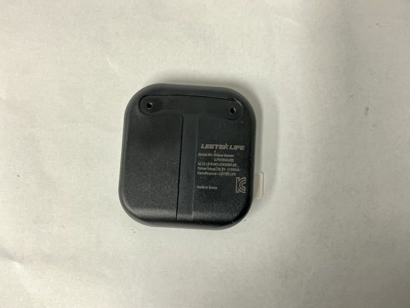
2BDLQ-LFW2930-02
Jan 29, 2026Diper Sensor
Equipment Class
DTS - Digital Transmission System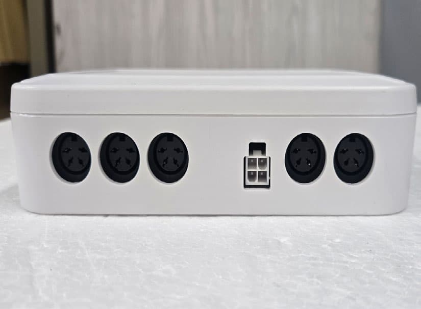
2BDLQ-LFW2937-01
Jan 29, 2026Bed controller
Equipment Class
DTS - Digital Transmission System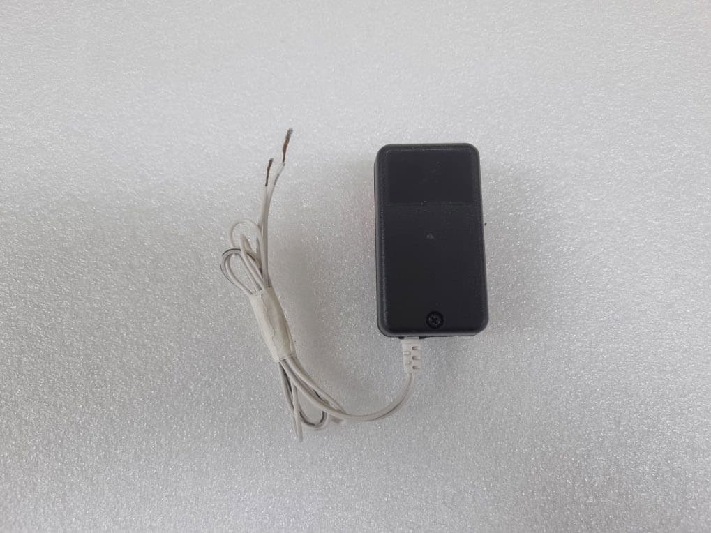
2BDLQ-LFW2939-01
Oct 13, 2024Fall prevention sensor
Equipment Class
DTS - Digital Transmission System