2BE57GWV1Panel Mount Node
GRACE TECHNOLOGIES, INC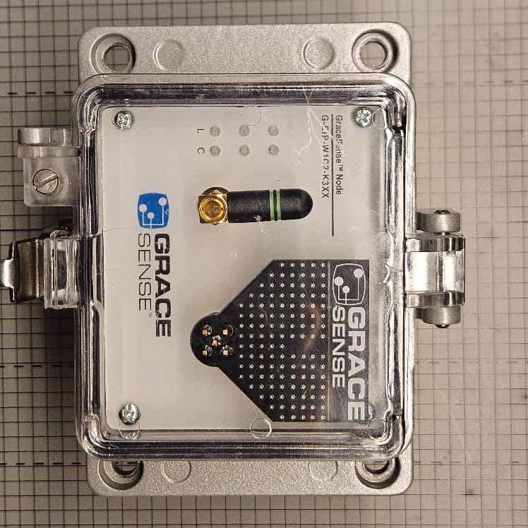
Click to zoom
Application Details
- Equipment Class
- DTS - Digital Transmission System
- Date of Grant
- May 04, 2026
- Application Purpose
- Original Equipment
- Equipment Note
- Panel Mount Node
- Frequency Range
- 2405.00000000 - 2480.00000000
- Company
- GRACE TECHNOLOGIES, INC
- Country
- United States
Documents & Files
Document Text
Text extracted from the exhibit documents filed with the FCC. Open a document above to read the original.
Users Manual
Actual product appearance may differ based on your unique configuration. This instruction sheet provides important information regarding installation of GraceSense™ Panel-Mount Nodes, CloudGates ™ ControlGates ™ . Please read these instructions in their entirety, and follow all safety instructions before attempting installation. The Panel-Mount Node ™ should be installed by technically qualified personnel. Failure to install the node in accordance with applicable codes and regulations and according to the manufacturer’s specified guidelines may result in electrical shock, fire hazard, poor performance or equipment failure, and may also void the product warranty. Warning: Only qualified persons who are familiar with the equipment being serviced and those who have received proper safety training related to the hazards of the equipment should attempt to install these sensors. The individual must also possess proper tools, training, and be capable of repair or modification of the related equipment and its accessories. Installation should conform to appropriate codes and standards. Failure to follow these instructions may result in serious personal injury, death and/or property damage. Always follow your facility’s PPE requirements when performing the installation and maintenance tasks on your equipment. Electrical Hazard Warning: The Panel-Mount Node/ CloudGate installation require wired connections inside your equipment panel. Do not attempt to install these nodes while the equipment is energized. Disconnect, lockout and tagout the input power source to your panel/equipment before installing or servicing these nodes. OVERVIEW The GraceSense ™ Node/CloudGate is an environmentally rated assembly mounted on the door of an enclosure. This assembly can be used in conjunction with our GraceSense™ Vibration & Temperature Node and Hot Spot Monitor or stand-alone. The Panel-Mount Node ™ , CloudGate ™ , and ControlGates ™ may consist of several transducer and sensor inputs, radios, power, and integration options based on the preselected configuration. GraceSense ™ Panel-Mount ™ Nodes are configurable to meet the needs of your application. You may have a Node that takes in hardwired sensor inputs, a CloudGate ™ (Node with cloud connection), a ControlGate ™ (Node with control integration), or a combination of these capabilities. The specific type you have can be determined by the part number, communication interfaces/ radios, or application interfaces. Reach out to Grace at [email protected] for more information on the capabilities of our specific model. BATTERY ASSEMBLY INSTRUCTIONS (Applicable only if ordered with a battery) 1.Locate the battery supplied with the node. 2. Position the new battery on the node by aligning the 6-pin connector and mounting screws of the battery to match the corresponding locations on the node. 3. Insert all three battery mounting screws by turning clockwise until threads start to engage. 4. Use a 6 -lobe T15 driver to tighten battery screws up to, but not exceeding the torque value of 2.5 in. lbs. 5. To replace battery, refer to the battery replacement instructions shipped with the new battery Note: Do not attempt to disassemble GraceSense™ Node other than the external mounted battery. There are no user-serviceable components inside the node and battery assembly. Tampering with the product may void the warranty. INSTALLATION All installations are intended to be mounted in or on an enclosure. Installation should be performed by a qualified technician and adhere to applicable regulatory codes. These devices are intended to be mounted on the flat surface of enclosures having the same type environmental ratings. Note: Each Zigbee radio has a range of 30m radius line-of-sight. Antenna Positioning As a general rule, the antenna(s) should be positioned vertically (as shown in the images above). During installation, positioning the Node upright with the antennas oriented vertically will provide the best reception. Power Source The GraceSense™ Node requires power via 5V, USB Mini B, 24V DC, or 120V AC with power adapter (sold separately). When used with a battery pack, the node can be self-powered or the battery pack is used as a backup when the primary power is not available. (Continued on back) Warning: Verify an electrical conductor has been de-energized using an adequately rated test instrument before working on it. Follow appropriate Energy Control (Lockout/Tagout) procedures as per OSHA Subpart S. © Grace Technologies, Inc. All rights reserved. Specifications are subject to change with/without notice. GS-PMCG-IG-EN 2004 1515 East Kimberly Road • Davenport, IA • www.graceport.com • 1.800.280.9517 PANEL-MOUNT NODE INSTALLATION GUIDE 2.31 58.8 1.60 [40.7] 5.08 [129.0] Ø0.45 x 0.22 [Ø11.5 x 5.5] Ø0.26±.004 [Ø6.5±0.1] 3.54 [90.0] Once installed, interface connections will be made from within the panel enclosure. Note: De-energize the equipment, and follow your facility’s Lockout/Tagout procedures before attempting to make connections to the node inside your panel/enclosure. All installations: 1) Cut panel opening and mount housing assembly to enclosure with supplied gasket. (Refer to the below dimensions for panel cut-out details). 2) Connect low voltage interface wiring according to documentation provided with the unit. On units configured for optional AC power: 1) Connect outlet device as per code. Note: It is the responsibility of the installer to ensure adequate separation of high and low voltage circuits in the end-use product. MECHANICAL SPECIFICATIONS Housing: Cast aluminum base Latch: Type 304 Stainless Steel Cover: Polycarbonate, UV rated, V-O Flame rated Insert Material: Acrylic UL94HB QUESTIONS For questions or technical support, please contact us at 1-800-280-9517. PANEL CUTOUT OVERALL DIMENSIONS LED INDICATION CHART Upon installation, please refer to GraceSense™ LED Indication Guide for determining what the LED indications mean. Once the installation is complete, …
Text truncated - open the document above for the full version.
Attestation Statements
1515 E Kimberly Rd Davenport, IA 52807 GRACE TECHNOLOGIES 1515 East Kimberly Rd. • Davenport, IA 52807 Office 563.823.5511 • [email protected] • www.graceport.com ATTENTION: FCC Certification – Section 2.911(d)(7) Information Designated U.S. Agent Company Name: Grace Technologies Contact Name: Andrew T. Zimmerman Street Address: 1515 E. Kimberly Rd. City/Province/Zip : Davenport, IA 52807 Telephone No: 563-386-9596 Fax No: 563-386-9639 email: [email protected] FRN #: 0034924886 This letter is to confirm that we (“the Designated U.S. Agent) have accepted the responsibility to act as the Designated U.S. Agent for Service of Process as required by section 47 CFR 2.911(d)(7) on behalf of the Applicant noted below. U.S. Agent Signature: __________________________________ Date: March 9, 2026______________________ Signed by (Printed Name/Title): Andrew T. Zimmerman, CTO__________ The Applicant acknowledges that they must maintain an agent for no less than one year after terminating all marketing and importation OR the conclusion of any Commission-related proceeding involving the equipment. The applicant further acknowledges their responsibility to inform the FCC whenever the Designated U.S. Agent information above changes. Applicant Company name: Grace Technologies Grantee Code: 2BE57 FRN #: 0034924886 Contact Name: Andy Zimmerman Street Address: 1515 E. Kimberly Rd. City/Province/Zip: Davenport, IA 52807 Telephone No: 563-386-9596 Email: [email protected] Applicant Signature: __________________________________ Date: March 9, 2026______________________ Signed by (Printed Name/Title): Andrew T. Zimmerman, CTO__________
Attestation Statements
1515 E Kimberly Rd Davenport, IA 52807 GRACE TECHNOLOGIES 1515 East Kimberly Rd. • Davenport, IA 52807 Office 563.823.5511 • [email protected] • www.graceport.com RE: FCC ID: 2BE57GWV1, FRN: 0034924886 Date: March 12, 2026 To Whom It May Concern: Statement for 47 CFR section 2.911(d)(5)(i) Grace Technologies certifies that as of the date of the application the equipment for which authorization is sought is not “covered” equipment 1 prohibited from receiving an equipment authorization pursuant to section 2.903 of the FCC rules. If the equipment for which the applicant seeks authorization is produced by any of the entities identified on the current Covered List, including affiliates or subsidiaries of the named companies, the applicant must include an explanation on why the equipment is not “covered” equipment. Additional Explanation: Not Applicable Statement for 47 CFR section 2.911(d)(5)(ii) Grace Technologies (“the applicant”) certifies that, as of the date of the filing of this application, the applicant is not identified on the Covered List as an entity producing “covered” equipment. Grantee (“the applicant”) also certifies that, the device does not have cybersecurity and/or anti-virus software produced by Kaspersky Lab, Inc. or any of its successors and assignees, identified on the Covered list installed on the device, nor will it be installed by the applicant anytime after certification. Dated this twelfth day of March, 2026. By: Andrew T. Zimmerman CTO, Grace Technologies [email protected] 563-823-5511 1 - The Commission’s Covered List is published by the Public Safety and Homeland Security Bureau and posted on the Commission’s website. This Covered List, which is periodically updated, identifies particular equipment, produced by particular entities, that constitutes “covered” equipment. https://www.fcc.gov/supplychain/coveredlist .
Cover Letter(s)
Willow Run (WR) Test Labs, Inc. 7117 Fieldcrest Dr., Brighton, Michigan 48116 USA Tel: (734) 252-9785, Fax: (734) 926-9785, e-mail: [email protected] Attn.:Federal Communications Commission Equipment Approval Services P.O. Box 358315 Pittsburgh, PA 15251-5315 Re: Certification for Grace Technologies, Inc. GWV1 FCC ID: 2BE57GWV1 If necessary, we have enclosed application materials for certification of Grace Technologies, Inc. GWV1. It has been verified to comply with CFR Title 47, Part 15.247/15.109. Current Variants: There are 2 types of variants: One populated with an pre-certified Wi-Fi radio (FCC ID: YOPGS2011MIE, IC: 9154A-GS2011MIE) and the other populated with an pre-certified LTE radio (FCC ID: XMR201707BG96, IC: 10224A-201709BG96), where the only difference is the choice of additional radio required for the gateway network. Within each type of variant there is only a single type of antenna: external SMA monopole antenna, which will be permanently attached using red Loctite 271 during assembly. The EUT is capable of being configured to support multiple bus protocols in software at the manufacturer assembly plant prior to shipping. If there are any questions regarding the application or testing performed, please contact us at the above address or call (734) 252-9785, or e-mail [email protected]. Sincerely, Joseph D. Brunett Willow Run (WR) Test Labs, Inc. 10 Willow Run (WR) Test Labs, Inc. 7117 Fieldcrest Dr., Brighton, Michigan 48116 USA Tel: (734) 252-9785, Fax: (734) 926-9785, e-mail: [email protected] Attn.:Certification a nd Engineering Bureau, I nnovation, S cience a nd Economic Development Canada 3701 Carling Avenue, Bldg. 94 Ottawa, Ontario K2H 8S2 Re: Certification f or Grace T echnologies, I nc. GWV1 IC: 32885–GWV1 If necessary, we have enclosed application materials for certification o f Grace T echnologies, I nc. G W V1. I t h as been verified to comply with IC RSS-247v4/GENe. Current Variants: There are 2 types of variants: One populated with an pre-certified Wi-Fi radio (FCC ID: YOPGS2011MIE, IC: 9154A-GS2011MIE) and the other populated with an pre-certified LTE radio (FCC ID: XMR201707BG96, IC: 10224A-201709BG96). These variants employ the same hardware where the only difference between them is the choice of additional radio required for the gateway network. Within each type of variant there is only a single type of antenna: external SMA monopole antenna, which will be permanently attached using red Loctite 271 during assembly. The EUT is capable of being configured to support different SIM cards for the cellular network and to support multiple bus protocols in software at the manufacturer assembly plant prior to shipping. This results in many possible PMN's as described in the Annex - PMN Definition provided at the end of this letter. If there are any questions regarding the application or testing performed, please contact us at the above address or call (734) 252-9785, or e-mail [email protected]. Sincerely, Joseph D. Brunett Willow Run (WR) Test Labs, Inc. 11 Annex - PMN Definition Canada CN: 32885-GWV1 PMN No. Description G-xxx-W1W2Wi-Fi variant G-xxx-W1CyLTE variant Where: xxx = EIP for Ethernet/IP communication protocol option MIP for MODBUS-TCP/IP communication protocol option y = Choice of cellular SIM card 1 = US based AT&T 2 = US based Verizon 3 = Global roaming hologram without Verizon option 4 = Global roaming hologram with Verizon option
Cover Letter(s)
Willow Run (WR) Test Labs, Inc. 7117 Fieldcrest Dr., Brighton, Michigan 48116 USA Tel: (734) 252-9785, Fax: (734) 926-9785, e-mail: [email protected] Re: Certification for Grace Technologies, Inc. FCC ID: 2BE57GWV1 IC: 32885–GWV1 REQUEST FOR CONFIDENTIALITY Pursuant to USA FCC 47 CFR 0.457(d) and 0.459 and Canada IC RSP-100, Section 10, Grace Technologies, Inc. requests that a part of the subject application be held confidential. Grace Technologies, Inc. has spent substantial effort in developing this product and it is one of the first of its kind in industry. Having the subject information easily available to ”competition” would negate the advantage they have achieved by developing this product. Not protecting the details of the design will result in financial hardship. Exhibit Conf. TypeRational Exh 04 - Block DiagramPermanentIncludes proprietary internal oscillator frequency information. Exh 05 - SchematicsPermanentIncludes proprietary design information Exh 10 - BOM + PlacementPermanentIncludes proprietary design information Exh 12 - Operating DescriptionPermanentIncludes proprietary design information Long Term Confidentiality (Permanent):Grace Technologies, Inc. requests that any exhibits listed above as permanently confidential be permanently withheld from public review. Wherein Long Term Confidentiality is not an option for specific exhibits with ISED, this request applies only to the FCC application for those exhibits. Short-Term Confidentiality (FCC Only):Grace Technologies, Inc. requests that any exhibits selected above as short term confidential be withheld from public view for a period of days (noted above) from the date of the Grant of Equipment Authorization and prior to marketing. If there are any questions regarding the application or testing performed, please contact us at the above address or call (734) 252-9785, or e-mail [email protected]. Sincerely, Joseph D. Brunett Willow Run (WR) Test Labs, Inc. 9
ID Label/Location Info
HVIN: Z-100-IOT-ZBR FCC ID: 2BE57GWV1 IC: 32885-GWV1 This device contains FCC ID: XMR201707BG96 IC: 10224A-201709BG96 This device complies with Part 15 of the FCC Rules and with Industry Canada license- exempt RSS standard(s). Operation is subject to the following two conditions: (1) This device may not cause harmful interference, and (2) This device must accept any interference received, including interference that may cause undesired operation. 8.5cm 6.5 c m Label is printed directly on product backplate Applies to G-AAA-W1CB-K3XX SKUs: G-EIP-W1C1-K3XX G-EIP-W1C2-K3XX G-EIP-W1C3-K3XX G-EIP-W1C4-K3XX G-MIP-W1C1-K3XX G-MIP-W1C2-K3XX G-MIP-W1C3-K3XX G-MIP-W1C4-K3XX Label for 802.15.4 plus LTE HVIN: Z-100-IOT-ZBR FCC ID: 2BE57GWV1 IC: 32885-GWV1 This device contains FCC ID: YOPGS2011MIE IC: 9154A-GS2022MIE This device complies with Part 15 of the FCC Rules and with Industry Canada license- exempt RSS standard(s). Operation is subject to the following two conditions: (1) This device may not cause harmful interference, and (2) This device must accept any interference received, including interference that may cause undesired operation. 8.5cm 6.5 c m Label is printed directly on product backplate Applies to G-AAA-W1W2-K3XX SKUs: G-EIP-W1W2-K3XX G-MIP-W1W2-K3XX Label for 802.15.4 plus WiFi
Internal Photos
IEEE 802.15.4 + Pre-certified Wi-Fi Option Pre-certified Wi-Fi PCB IEEE 802.15.4 PCB IEEE 802.15.4 PCB Pre-certified Wi-Fi PCB IEEE 802.15.4 PCB Pre-certified Wi-Fi PCB IEEE 802.15.4 PCB IEEE 802.15.4 PCB Pre-certified Wi-Fi PCB IEEE 802.15.4 + Pre-certified LTE Option IEEE 802.15.4 PCB Pre-certified LTE PCB IEEE 802.15.4 PCB Pre-certified LTE PCB IEEE 802.15.4 PCB Pre-certified LTE PCB Pre-certified LTE PCB Pre-certified LTE PCB
RF Exposure Info
Willow Run (WR) Test Labs, Inc. 7117 Fieldcrest Drive Brighton, MI 48116 Phone: (734) 252-9785, Fax (734) 926-9785 e-mail:[email protected] RF EXPOSURE CALCULATIONS Summary: The EUT with all transmitters is compliant with both the FCC power density limit and the ISED Exposure Evaluation limits. Requirement: According to USA CFR 15 §1.1307 (b)(1), systems operating under the provisions of this section shall be operated in a manner that ensures the public is not exposed to radio frequency energy level in excess of the Commission’s guidelines. For Canada, RSS-102 sets out the requirements and measurement techniques used to evaluate radio frequency (RF) exposure compliance of radiocommunication apparatus designed to be used within the vicinity of the human body. USA REF: IC REF: Min. Sep. Distance:20 cm SrlFrl StartStop(RMS)(RMS)Tune Up (Avg)(Avg)Table 5 Srl Ratio Section 6.6 Frl RatioMPE Ratio MHzMHzdBmWdB dBuV/m mW/cm2mW/cm2W R1 Zigbee 2405.002480.00 6.00.0051.000 125.722 0.0010.5360.0022.6980.0020.001 R2 LTE 698.001910.00 28.00.6310.000 146.722 0.1260.2300.5461.1570.5450.822 R3 Wi-Fi 2412.002467.00 22.40.1750.000 141.162 0.0350.5370.0652.7030.0650.002 R4 R5 Total MPE0.548Total MPE0.547 Total MPE 0.823 R6 MPE Ratio < 1YESMPE Ratio < 1YES MPE Ratio < 1 YES #C1C2C3C4C5C6C7C8C9C10C11C12 C13C14C15 (ROW) (COLUMN) R0C4 R0C5 R0C6 R0C7 R0C8 R0C9 R2C2/C3 R2C4/C5 R3C4/C5 R6 C10/C12/C15 1.000 Active 3m R0 Mode Frequency Band Canada ISED RSS-102 EUT Mode: Meas. Distance: E20cm Canada ISED Safety Code 6 EIRP+Tune Up 17-Feb-26 J. Nantz Grace GWV1 1.1310, 2.1091/1093, 447498 D01 General RF Exposure Guidance v06 RSS-102 Issue 6, Safety Code 6 Test Date: Test Engineer: EUT: NOTE: No duty factor were applied to demonstrate compliance EIRP(W) = 10^(EIRP (dBm)+Tune up)/10*0.001 TUNE UP – The manufacturer declares +/-1dB tune up. E20cm = EIRP+Tune Up+95.2+20*LOG(3/0.2) EIRP+Tune up (mW) = S (mW/cm^2)/ 4 x PI x 20cm^2 mW/cm2 limit = 0.1*W/m2 Band 12 LTE operating frequency used to demonstrate worst case Srl. Maximum power including tune-up per TAtechnology Co., Ltd. MPE report # RXA1706-0199MPE Maximum power including tune-up per GainSpan Corporation. report # R1402132-247, Rev A Maximum ratio using LTE radio co-location EIRP+DutyS20cm MPE Limit Table 1 USA FCC 1.1310 MPE (mW/cm^2) 1.000 0.465
Test Report
Amber Helm Development L.C. 92723 Michigan Hwy-152 Sister Lakes, Michigan 49047 USA Contact: [email protected], +1 (734) 252-9505 GWV1-WR2605RFr3 Issued: March 18, 2026 EMC Test Report regarding USA: CFR Title 47, Part 15.247/15.109(Emissions) Canada:IC RSS-247v4/GENe(Emissions) for GWV1 Category: Wireless Gateway Node Judgments: Aligns with FCC 15.247, ISED RSS-247v4 Testing Completed: March 4, 2026 TESTING NVLAP LAB CODE 200129-0 Prepared for: Grace Technologies, Inc. 1515 East Kimberly Rd., Davenport IA 52807 Phone: (563) 386 9596, Fax: (563) 386 9639 Contact: Bryce Brewer, [email protected] Data Rec./Rev. by: Rpt. Auth. by: John NantzDr. Joseph Brunett, EMC-002790-NE Rpt. Prep./Rev. by:Date of Issue:March 18, 2026 John Nantz A copy of this report will remain on file until March 2036.Page 1 of 26 Date: March 18, 2026Prepared For: Grace Technologies, Inc.Report No.: GWV1-WR2605RFr3 Revision History Rev. No.DateDetailsRevised By r0March 18, 2026Initial Release.J. Nantz r1April 13, 2026Minor clarificationsJ. Nantz r2April 24, 2026Minor clarificationsJ. Nantz r3April 30, 2026Correct photosJ. Nantz Contents Revision History2 Table of Contents2 1 Test Report Scope and Limitations4 1.1 Laboratory Authorization . . . . . . . . . . . . . . . . . . . . . . . . . . . . . . . . . . . . . . . . . . .4 1.2 Report Retention . . . . . . . . . . . . . . . . . . . . . . . . . . . . . . . . . . . . . . . . . . . . . . . .4 1.3 Subcontracted Testing . . . . . . . . . . . . . . . . . . . . . . . . . . . . . . . . . . . . . . . . . . . . .4 1.4 Test Data . . . . . . . . . . . . . . . . . . . . . . . . . . . . . . . . . . . . . . . . . . . . . . . . . . . .4 1.5 Limitation of Results . . . . . . . . . . . . . . . . . . . . . . . . . . . . . . . . . . . . . . . . . . . . . .4 1.6 Copyright . . . . . . . . . . . . . . . . . . . . . . . . . . . . . . . . . . . . . . . . . . . . . . . . . . . .4 1.7 Endorsements . . . . . . . . . . . . . . . . . . . . . . . . . . . . . . . . . . . . . . . . . . . . . . . . . .4 1.8 Test Location . . . . . . . . . . . . . . . . . . . . . . . . . . . . . . . . . . . . . . . . . . . . . . . . . .5 1.9 Traceability and Equipment Used . . . . . . . . . . . . . . . . . . . . . . . . . . . . . . . . . . . . . . .5 2 Test Specifications and Procedures6 2.1 Test Specification and General Procedures . . . . . . . . . . . . . . . . . . . . . . . . . . . . . . . . . .6 3 Configuration and Identification of the Equipment Under Test7 3.1 Description and Declarations . . . . . . . . . . . . . . . . . . . . . . . . . . . . . . . . . . . . . . . . .7 3.1.1EUT Configuration . . . . . . . . . . . . . . . . . . . . . . . . . . . . . . . . . . . . . . . . . . .8 3.1.2Modes of Operation . . . . . . . . . . . . . . . . . . . . . . . . . . . . . . . . . . . . . . . . . .9 3.1.3Variants . . . . . . . . . . . . . . . . . . . . . . . . . . . . . . . . . . . . . . . . . . . . . . . . .9 3.1.4Test Samples . . . . . . . . . . . . . . . . . . . . . . . . . . . . . . . . . . . . . . . . . . . . . .9 3.1.5Functional Exerciser . . . . . . . . . . . . . . . . . . . . . . . . . . . . . . . . . . . . . . . . . .9 3.1.6Modifications Made . . . . . . . . . . . . . . . . . . . . . . . . . . . . . . . . . . . . . . . . . .9 3.1.7Production Intent . . . . . . . . . . . . . . . . . . . . . . . . . . . . . . . . . . . . . . . . . . .9 3.1.8Declared Exemptions and Additional Product Notes . . . . . . . . . . . . . . . . . . . . . . . .9 4 Emissions10 4.1 General Test Procedures . . . . . . . . . . . . . . . . . . . . . . . . . . . . . . . . . . . . . . . . . . . . 10 4.1.1Radiated Test Setup and Procedures . . . . . . . . . . . . . . . . . . . . . . . . . . . . . . . . . 10 4.1.2Conducted Emissions Test Setup and Procedures . . . . . . . . . . . . . . . . . . . . . . . . . . 12 4.1.3Power Supply Variation . . . . . . . . . . . . . . . . . . . . . . . . . . . . . . . . . . . . . . . . 12 4.2 Intentional Emissions . . . . . . . . . . . . . . . . . . . . . . . . . . . . . . . . . . . . . . . . . . . . . . 13 4.2.1Duty and Transmission Cycle, Pulsed Operation . . . . . . . . . . . . . . . . . . . . . . . . . . 13 4.2.2Fundamental Emission Bandwidth . . . . . . . . . . . . . . . . . . . . . . . . . . . . . . . . . . 15 4.2.3Effective Isotropic Radiated Power . . . . . . . . . . . . . . . . . . . . . . . . . . . . . . . . . . 17 4.2.4Power Spectral Density . . . . . . . . . . . . . . . . . . . . . . . . . . . . . . . . . . . . . . . . 19 4.3 Unintentional Emissions . . . . . . . . . . . . . . . . . . . . . . . . . . . . . . . . . . . . . . . . . . . . 21 4.3.1Restricted Band Transmit Chain Spurious Emissions . . . . . . . . . . . . . . . . . . . . . . . . 21 4.3.2OOB Transmit Chain Spurious Emissions . . . . . . . . . . . . . . . . . . . . . . . . . . . . . . 23 Amber Helm Development L.C.Page 2 of 26 Date: March 18, 2026Prepared For: Grace Technologies, Inc.Report No.: GWV1-WR2605RFr3 4.3.3Conducted Emissions Test Results - AC Power Port(s) . . . . . . . . . . . . . . . . . . . . . . . 24 5 Measurement Uncertainty and Accreditation Documents26 List of Tables 1.8.0 Test Site List. . . . . . . . . . . . . . . . . . . . . . . . . . . . . . . . . . . . . . . . . . . . . . . . . . .5 1.9.0 Equipment List. . . . . . . . . . . . . . . . . . . . . . . . . . . . . . . . . . . . . . . . . . . . . . . . .5 3.1.0 EUT Declarations. . . . . . . . . . . . . . . . . . . . . . . . . . . . . . . . . . . . . . . . . . . . . . . .7 4.2.1 Pulsed Emission Characteristics (Duty Cycle). . . . . . . . . . . . . . . . . . . . . . . . . . . . . . . . 13 4.2.2 Intentional Emission Bandwidth. . . . . . . . . . . . . . . . . . . . . . . . . . . . . . . . . . . . . . . . 15 4.2.3 Tx. Power Results. . . . . . . . . . . . . . . . . . . . . . . . . . . . . . . . . . . . . . . . . . . . . . . . 17 4.2.4 Power Spectral Density Results. . . . . . . . . . . . . . . . . . . . . . . . . . . . . . . . . . . . . . . . . 19 4.3.1 (i) Transmit Chain Spurious Emis…
Text truncated - open the document above for the full version.
Test Report
SPE-11-8-0036/I/SS Page 1 of 13 SPECIFICATION Part No. : GW26.0112 Product Name : 2.4GHz Miniature Terminal Mount Monopole Antenna Feature : SMA(M)R/A Connector 28.5 * 17.2mm ROHS Compliant SPE-11-8-0036/I/SS Page 2 of 13 1 Introduction The GW.26 2.4GHz Monopole SMA(M)R/A terminal mount antenna is ideal for 2.4GHz wireless applications such as Bluetooth and Wireless LAN. Many module manufacturers specify peak gain limits for any antennas that are to be connected to that module. Those peak gain limits are based on free-space conditions. In practice, the peak gain of an antenna tested in free-space can degrade by at least 1 or 2dBi when put inside a device. So ideally you should go for a slightly higher peak gain antenna than mentioned on the module specification to compensate for this effect, giving you better performance. Upon testing of any of our antennas with your device and a selection of appropriate layout, integration technique, or cable, Taoglas can make sure any of our antennas’ peak gain will be below the peak gain limits. Taoglas can then issue a specification and/or report for the selected antenna in your device that will clearly show it complying with the peak gain limits, so you can be assured you are meeting regulatory requirements for that module. For example, a module manufacturer may state that the antenna must have less than 2dBi peak gain, but you don’t need to select an embedded antenna that has a peak gain of less than 2dBi in free-space. This will give you a less optimized solution. It is better to go for a slightly higher free-space peak gain of 3dBi or more if available. Once that antenna gets integrated into your device, performance will degrade below this 2dBi peak gain due to the effects of GND plane, surrounding components, and device housing. If you want to be absolutely sure, contact Taoglas and we will test. Choosing a Taoglas antenna with a higher peak gain than what is specified by the module manufacturer and enlisting our help will ensure you are getting the best performance possible without exceeding the peak gain limits. Connector mount is fully customizable. SPE-11-8-0036/I/SS Page 3 of 13 2 Specification Wi-Fi 2.4GHz Frequency 2400~2500MHz Bandwidth 100MHz Peak Gain 1.8dBi Radiation Efficiency > 40% Radiation Omni-directional Polarization Vertical Power Handling 1W Max Power Handling 1W Max Electrical Wave ½ Monopole Impedance 50Ω Operating Temperature -40°C ~ +85°C Storage Temperature -40°C ~ +85°C 3 Mechanical Properties Mechanical Properties Colour Black and Green IP rating IP-65 Connector SMA(M) R/A SPE-11-8-0036/I/SS Page 4 of 13 4 Antenna Characteristics 4.1 Antenna S11 SPE-11-8-0036/I/SS Page 5 of 13 4.2 Antenna Peak Gain -4 -3 -2 -1 0 1 2 3 235023602370238023902400241024202430244024502460247024802490250025102520253025402550 Freq(MHz) Peak Gain(dBi) Peak Gain (dBi) SPE-11-8-0036/I/SS Page 6 of 13 4.3 Antenna Efficiency 0 10 20 30 40 50 60 2350 2360 2370 2380 2390 2400 2410 2420 2430 2440 2450 2460 2470 2480 2490 2500 2510 2520 2530 2540 2550 Freq(MHz) Efficiency(%) Efficiency (%) SPE-11-8-0036/I/SS Page 7 of 13 4.4 Antenna pattern (XY plane) Z Y X SPE-11-8-0036/I/SS Page 8 of 13 4.5 Antenna pattern (XY plane) -40 -35 -30 -25 -20 -15 -10 -5 0 5 0 30 60 90 120 150 180 210 240 270 300 330 2400MHz 2420MHz 2440MHz 2460MHz 2480MHz 2500MHz SPE-11-8-0036/I/SS Page 9 of 13 4.6 Antenna pattern (XZ plane) -40 -35 -30 -25 -20 -15 -10 -5 0 0 30 60 90 120 150 180 210 240 270 300 330 2400MHz 2420MHz 2440MHz 2460MHz 2480MHz 2500MHz SPE-11-8-0036/I/SS Page 10 of 13 4.7 Antenna pattern (YZ plane) -40 -35 -30 -25 -20 -15 -10 -5 0 0 30 60 90 120 150 180 210 240 270 300 330 2400MHz 2420MHz 2440MHz 2460MHz 2480MHz 2500MHz SPE-11-8-0036/I/SS Page 11 of 13 5. Outline Drawings and Structure Key 1 Connector SMA(M)RA Brass 2 Antenna Cover TPEE (Black) 3 Colour Stripes Apple Green – Acrylic Paint 6. Packaging SPE-11-8-0036/I/SS Page 12 of 13 SPE-11-8-0036/I/SS Page 13 of 13 Taoglas makes no warranties based on the accuracy or completeness of the contents of this document and reserves the right to make changes to specifications and product descriptions at any time without notice. Taoglas reserves the rights to this document and the information contained herein. Reproduction, use or disclosure to third parties without express permission is strictly prohibited. © Taoglas
Contact Information
Applicant
Bryce Brewer(Product Engineer)
[email protected]Fax: 563-386-9639
Technical Contact
Grace TechnologiesAndrew T. Zimmerman
[email protected]Fax: 563-386-9639
1515 E. Kimberly Rd. · Davenport, Iowa, 52807 · United States
Test Firm
AHD (Amber Helm Development, L.C.)Gordon Helm
[email protected]Fax: 269-429-9016
Technical Specifications
| # | Rule Parts | Frequency Range | Power Output |
|---|---|---|---|
| 1 | 15C | 2.40 GHz - 2.48 GHz | 3.00 mW |