2BE7T-EXO18Exoskeleton
exoIQ GmbH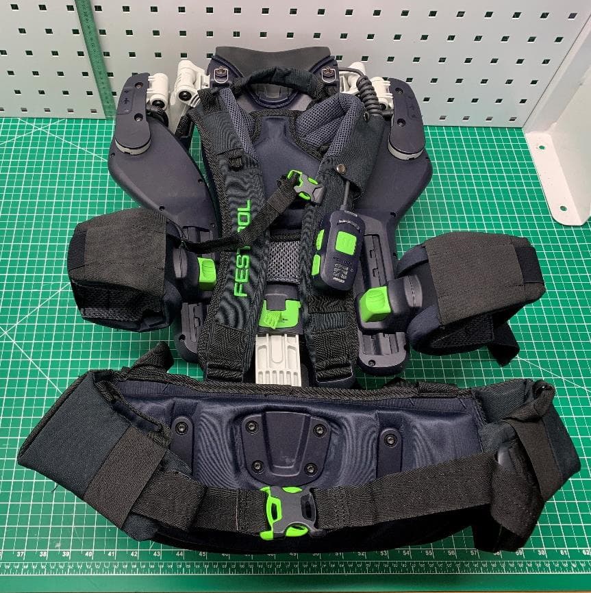
Click to zoom
Application Details
- Equipment Class
- DTS - Digital Transmission System
- Date of Grant
- Aug 28, 2024
- Application Purpose
- Original Equipment
- Date of Application
- Aug 28, 2024
- Equipment Note
- Exoskeleton
- Frequency Range
- 2402.00000000 - 2480.00000000
- Company
- exoIQ GmbH
- Country
- Germany
Documents & Files
Document Text
Text extracted from the exhibit documents filed with the FCC. Open a document above to read the original.
Users Manual
enOriginal instructions – exoskeleton11 frNotice d'utilisation d'origine - Exosquelette24 esManual de instrucciones original - Exoesqueleto38 Read all instructions before using Lire toutes les instructions avant de démarrer les travaux. Lea y comprende todas las instrucciones antes de usar. EXO 18 EXOACTIVE Hersteller / Manufacturer: Festool GmbH Wertstraße 20 73240 Wendlingen Germany +49 (0)70 24/804-0 www.festool.com 10790209_A / 2024-03-26 1 1-3 1-4 1-6 1-8 1-9 1-2 1-12 1-13 1-14 1-11 1-10 1-1 1-15 1-16 1-7 1-17 1-5 1-5 1 2 1 3-1 click click 2A 2B 3A 3B 5-1 5-4 5-3 5-2 5A 3 2 1 4-3 4-4 4-5 4-6 4-7 4-8 4-9 4-2 4-1 4 5-10 5-5 5-7 5-9 5-6 5-8 5C 5B 2 1 3 2 1 64 - 65“132 66 - 67“142 68 - 69“253 70 - 71“263 72 - 73“374 74 - 75“484 > 75“5>85 64 - 65“232 66 - 67“242 68 - 69“353 70 - 71“464 72 - 73“574 74 - 75“685 > 75“6>85 64 - 65“232 66 - 67“342 68 - 69“453 70 - 71“564 72 - 73“674 74 - 75“785 > 75“7>85 64 - 65“011 66 - 67“022 68 - 69“132 70 - 71“243 72 - 73“354 74 - 75“364 > 75“4>65 64 - 65“011 66 - 67“122 68 - 69“232 70 - 71“343 72 - 73“354 74 - 75“464 > 75“4>65 64 - 65“111 66 - 67“222 68 - 69“232 70 - 71“343 72 - 73“454 74 - 75“464 > 75“5>65 6 2 1 2 1 8A 8B 7 7-1 7-2 7-3 8D 8E 8C 1 2 4 3 2 1 9A 9B 2 1 4 3 2 1 9C 9D 9E 2 1 2 1 2 1 Contents 1About this manual.....................................11 2Symbols.....................................................11 3Safety warnings.........................................11 4Intended use..............................................12 5Technical data...........................................13 6Device description.....................................13 7Battery pack..............................................13 8Commissioning..........................................13 9Settings......................................................14 10Working with the exoskeleton...................15 11Status indicator.........................................19 12Behaviour in the event of faults or acci dents..........................................................19 13Transport and storage..............................20 14Service and maintenance..........................20 15Accessories...............................................21 16Environment..............................................22 17General information..................................22 1About this manual Save these instructions It is important for you to read and understand this manual. The information it contains relates to protecting your safety and preventing prob lems. The symbols below are used to help you recognize this information. DANGERDescription of imminent hazard and failure to avoid hazard will result in death. WARN ING Description of hazard and possible resulting injures or death. CAUTIONDescription of hazard and possible resulting injuries. NOTICEDescription of possible damage of the device or its surroundings. 2Symbols Warning of general danger Warning of electric shock Read the operating manual and safety warnings. Prohibited for persons with active medical implants. Risk of pinching fingers and hands. Remove the battery pack. Inserting the battery pack. Tool contains a chip which stores data. See section 17.2 Tip or advice Handling instruction CAUTION For use only with FESTOOL batteries BP 18. ATTENTION À utiliser seulement avec les batteries FESTOOL BP 18. PRECAUCIÓN Para uso solamente con las baterías FESTOOL BP 18. CAUTION For use only with FESTOOL batteries BP 18 VVolt d.c Direct current AAmperes AhAmpere-hour MHzMegahertz dBmDecibel-milliwatts "Inch mmMillimeter lb.Pound kgKilogram °Fdegree Fahrenheit °Cdegree Celsius 3Safety warnings WARNING! Read all safety warnings and instructions. Failure to follow the safety warnings and instructions may result in electric shock, fire and/or serious in jury. Save all safety warnings and instructions for future reference. Follow the operating manual for the charger and the battery pack. –Do not open incorrectly. Guards must not be removed. Maintenance and repair must only be performed by a recognised special ist workshop. English 11 –The exoskeleton must not be used by persons (including children) with reduced physical, sensory or mental capabilities, or lack of experience and knowledge. En sure that children do not play with the exo skeleton. –Keep children and other persons away from the exoskeleton during use. –The exoskeleton must not be used by per sons with active medical implants. –Wearing the exoskeleton does not ex empt you from wearing suitable protective equipment. –Do not use power supply units or third- party battery packs to operate the exo skeleton. Do not use third-party chargers to charge the battery packs. The use of accessories not expressly authorised by the manufacturer can result in electric shocks and/or serious accidents. –Disconnect the battery pack from the de vice before you change the accessory parts/consumables, or place the device in storage. Such preventative safety meas ures reduce the risk of unintentionally starting the device. –Do not use the exoskeleton for safety-crit ical work, or for handling potentially dan gerous goods (e.g. open saw blades or live cables, hazardous goods, dangerous or hot liquids). Wearing the exoskeleton can affect the precision of arm movements. –Do not use the exoskeleton in the rain or in damp surroundings. Moisture in the exoskeleton may cause a short circuit and fire. –Never use the device in potentially explo sive environments. –Do not wear loose-fitting clothing or jew ellery. If you have long hair, wear a hair net or tie your hair up. Keep hair and clothing away from moving parts. Loose-fitting clothing, jewellery or long hair can be caught by moving parts. –Due to the way it protrudes from the body and its open strap ends, the exoskeleton is inherently unsuited to being used at work places where the wearing of close-fitting work clothing is prescribed. –Ensure that your posture is normal. En sure a secure stance and keep your bal ance at all…
Text truncated - open the document above for the full version.
Attestation Statements
Docusign Envelope ID: 030106FF-2C6A-4173-B12B-92E35390401A
Attestation Statements
Docusign Envelope ID: B52A0A32-2A73-46CB-93F0-EE32946EA06B
Attestation Statements
• • Docusign Envelope ID: 030106FF-2C6A-4173-B12B-92E35390401A
Cover Letter(s)
Docusign Envelope ID: 030106FF-2C6A-4173-B12B-92E35390401A
Cover Letter(s)
☒☒ ☒☐ ☒ ☒ ☐☐ ☐☐ ☒☐ Abschlusszertifikat Umschlag-ID: F08AA443CC6C48CEA01DD38F367E1AE7Status: Abgeschlossen Betreff: Hier ist Ihr signiertes Dokument: FCC Cover Letter_LTC STC_revManualFotos.pdf Quellumschlag: Dokumentenseiten: 1Signaturen: 1Umschlagersteller: Zertifikatsseiten: 2Initialen: 0Bernward Otten Signatur mit Anleitung: Deaktiviert Umschlag-ID-Stempel: Deaktiviert Zeitzone: (UTC+01:00) Amsterdam, Berlin, Bern, Rom, Stockholm, Wien Werstr, 20 Wendlingen, Baden-Württemberg 73240 [email protected] IP-Adresse: 212.222.145.219 Eintragsverfolgung Status: Original 26.08.2024 11:45:58 Inhaber: Bernward Otten [email protected] Standort: DocuSign UnterzeichnerereignisseSignaturZeitstempel Bernward Otten [email protected] Geschäftsführer Sicherheitsstufe: E-Mail, Kontoauthentifizierung (keine) Signaturübernahme: Hochgeladenes Signaturbild Mit IP-Adresse: 212.222.145.219 Gesendet: 26.08.2024 11:46:12 Eingesehen: 26.08.2024 11:46:17 Signiert: 26.08.2024 11:46:31 Selfservice-Signieren Vereinbarung bezüglich elektronischer Unterlagen und Signaturen: Nicht über DocuSign angeboten Vor-Ort-Unterzeichner – Ereignisse SignaturZeitstempel BearbeiterversandereignisseStatusZeitstempel BeauftragtenzustellereignisseStatusZeitstempel VermittlerversandereignisseStatusZeitstempel Zertifizierter Versand - EreignisseStatusZeitstempel KopienereignisseStatusZeitstempel Bernward Otten [email protected] Geschäftsführer Sicherheitsstufe: E-Mail, Kontoauthentifizierung (keine) Kopiert Gesendet: 26.08.2024 11:46:32 Eingesehen: 26.08.2024 11:47:01 Vereinbarung bezüglich elektronischer Unterlagen und Signaturen: Nicht über DocuSign angeboten Zeugen-EreignisseSignaturZeitstempel NotarereignisseSignaturZeitstempel Umschlagereignisse – Überblick StatusZeitstempel Umschlag gesendetHash-codiert/verschlüsselt26.08.2024 11:46:12 Zertifiziert zugestelltSicherheitsprüfung ausgeführt26.08.2024 11:46:17 Signiervorgang abgeschlossenSicherheitsprüfung ausgeführt26.08.2024 11:46:31 AbgeschlossenSicherheitsprüfung ausgeführt26.08.2024 11:46:32 ZahlungenStatusZeitstempel
Cover Letter(s)
Docusign Envelope ID: 99643063-88F2-423D-919F-ECBF6DB9C8E3
ID Label/Location Info
Größe dimensions Länge length Höhe height R: Sc hrift font Farbe colour Symbole symbols j ( )n ( x ) DINPro, grauweiss 10% K grauweiss 10% K Mindesthöhe/minimum height: mind. 5 mm, BA lesen / Herzschrittmacherverbot: 12 mm Logo Identsc hild identification sign Produktionshinweise production notes Festool schwarzblauHintergrund background 708045 - B- 19.03.2024 drsn 1 / 1 106511501:1 EXO-18 US Leistungsschild / Rating plate DRW DIN A4 70 38 2 Länge 30 mm, Festool grün Aufkleber label Toleranzen Aussenabmessung tolerances exterior Dimensions Toleranzen Radien tolerances radii Toleranzen Bedruckung tolerances printing + 0,2 - 0,4 + 0,5 - 0,5 + 0,2 - 0,2 Spezielle Angaben für externen Druck Special information for external printing Farben Colors Festool Grün green : 45/0/100/0 Hintergrund background schwarzblau/ darkblue: 83/75/54/70 Für Druckabnahme sind Referenzmuster aus Druckerei in Neidlingen erhältlich. For printing release original samples are available in the printery in Neidlingen. 122594 09.04.2024 drsn FCC ID xxx-EXO18 IC: xxxxxx-EXO18 XXXXXXX Electrical Safety Product & Service Questions? Call 888-337-8600 YYYY-MM 0002001x Festool GmbH · Wertstr. 20 73240 Wendlingen · Germany Made in Germany EXO 18 (US) T-Nr. 10715513 S-Nr. 4 A 18 V FCC ID: 2BE7T-EXO18 IC: 32110-EXO18 www.festool.com
Internal Photos
Separation distance Antenna – Surface Housing dmin = 6.52 mm
RF Exposure Info
Remark: The test results effects only to the related items tested at the time of the test. The test report shall not be reproduced except in full without the written approval of the testing laboratory. Information provided by the customer are identified in italic letters and may have an influence on the validity of test results. RF Exposure Statement Product / EUT: Exoskeleton Type designation: EXOACTIVE EXO 18 Tested type: EXOACTIVE EXO 18 Production level: 2023-04 S/N: 40022970 FCC ID: 2BE7T-EXO18 IC certification number: 32110-EXO18 Integrated RF-Modules RF Standard BLE Antenna: Integral Module installation: n/a Manufacturer: exoIQ GmbH Jaffestraße 12 21109 Hamburg / Germany Test remit: FCC Rules 47 CFR Part 1 Subpart I 09/13/2023 – §1.1307 (b) KDB 447498 D04 Interim General RF Exposure Guidance v01 The requirements were: kept not kept Test report 23-0121RP11-008-C 03/12/2024 Page 2 of 5 Applicant: exoIQ GmbH Jaffestraße 12 21109 Hamburg / Germany EUT- Date of arrival: 02/02/2024 Test ID: 23-0121PR05-015 Date(s) of test: 02/14/2024 Test laboratory: EMCE GmbH Ingenieurbüro für EMV-Prüfungen und Schaltungsentwicklung Untere Wiesen 1 / 88483 Burgrieden / Germany Project manager: Mr. S. Vogelmann Inspector: Mr. S. Vogelmann Approval: Mr. Chr. Vogelmann Test report 23-0121RP11-008-C 03/12/2024 Page 3 of 5 Determination of exemption: Rules and specification 47 CFR Part 1 Section 1307 (b)(1)(i)(B) KDB 447498 D04 Interim General RF Exposure Guidance v01 According to FCC §1.1307(b), systems operating under the provisions of this section shall be operated in a manner that ensure that the public is not exposed to radio frequency energy level in excess of the Commission’s guideline. A single RF source is exempt if the available maximum time-averaged power or effective radiated power (ERP), whichever is greater, is less than or equal to the threshold Pth (mW) described in the following formula. This method shall only be used at separation distances (cm) from 0.5 centimeters to 40 centimeters and at frequencies from 0.3 GHz to 6 GHz (inclusive). Pth is given by: P th (mW)= ERP 20cm (d/20cm) x d≤20 cm or P th (mW)= ERP 20cm 20 cm <d≤ 40 cm where 푥=−푙표푔 10 { 60 퐸푅푃 20푐푚 √푓 } f in GHz ERP 20cm (mW)={ 2040푓 3060 0.3 퐺퐻푧 ≤푓<1.5 퐺퐻푧 1.5 퐺퐻푧 ≤푓<6 퐺퐻푧 d = separation distance (cm) Example: Test frequency 2450 MHz d 0.5cm ERP 20cm (mW) 3060 Calculated P th (mW): 푥=−푙표푔 10 { 60 3060√2.45 } = 1.9022 P th (mW)= 3060(0.5/20cm) 1.9022 = 2.74 mW Test report 23-0121RP11-008-C 03/12/2024 Page 4 of 5 Records refer to Test report 23-0121RP11-007-C Conducted test Center Frequency / MHz ERP / mW Limit / mW Margin / mW 2402 2.453 1000 997.5 2440 2.543 1000 997.5 2480 2.638 1000 997.4 Radiated test Center Frequency / MHz ERP / mW Limit / mW Margin / mW 2402 2.109 1000 997,9 2440 2.291 1000 997,7 2480 1.91 1000 998,1 Determination of exemption The higher test results from the conducted test were used for the calculation. Center Frequency Maximum ERP Pth (d= 0.65 cm) Minimum separation distance SAR test exclusion (MHz) (dBm) (mW) (mW) (cm) 2402 3.897 2.453 4.587 0.65* Yes 2440 4.054 2.543 4.533 0.65* Yes 2480 4.197 2.638 4.479 0.65* Yes * Minimum distance between antenna structure and surface of the handheld device. Test result Maximum ERP ≤ Pth: kept not kept Test report 23-0121RP11-008-C 03/12/2024 Page 5 of 5 Summary 47 CFR Part 1 Subpart I Requirement Regulation section Operating Band Limits Result Remarks Exemption pursuant § 1.1307 (b)(1)(i)(A) n. r. n/a Evaluation of the human exposure to RF radiation § 1.1307 (b)(1)(i)(B) BLE @2.4 GHz General Population / Uncontrolled Exposure Pass No SAR required Environmental Assessment § 1.1307 (b)(1)(i)(C) n. r. n/a n. r. – not relevant Burgrieden, 08/27/2024 Responsible inspector: ____________________________________________ Project manager – Steffen Vogelmann - End of Test Report -
Test Report
Test report 23-0121RP11-007-C P roduct / EUT: Exoskeleton Type designation: EXOACTIVE EXO 18 Tested type: EXOACTIVE EXO 18 EUT authorization: Certification Suppliers Declaration of Conformity P roduction level: EUT 23-0121PR05-015 2023-04 EUT 23-0121PR05-016 2023-04 S/N: EUT 23-0121PR05-015 40023038 EUT 23-0121PR05-016 40025445 F CC ID: 2BE7T-EXO18 I C certification number: 32110-EXO18 PMN ExoActive HVI N 10715513 F VIN 10499807 M anufacturer: exoIQ GmbH Jaffestraße 12 21109 Hamburg / Germany Test remit: 47 CFR Part 15 – Subpart C – Intentional radiators RSS-247, Issue 3 (2023-08) RSS-Gen, Issue 5 (2018-04) - Amendment 1:2019-03 and Amendment 2:2021-02 in accordance with the procedures given in ANSI C63.10-2013 and ANSI C63.4a-2017 The standards were: kept kept, for the limited scope of testing not kept Remark: Validation covered by the accredited scope Validation not covered by the accredited scope according:__________ Validation of the EMC-requirements partly proceeded Remark: The test results effects only to the related items tested at the time of the test. The test report shall not be reproduced except in full without the written approval of the testing laboratory. Information provided by the customer are identified in italic letters and may have an influence on the validity of test results. Test report 23-0121RP11-007-C 03/12/2024 Page 2 of 99 Applicant: exoIQ GmbH Jaffestraße 12 21109 Hamburg / Germany EUT- Date of arrival: 02/02/2024 02/02/2024 Test I D: 23-0121PR05-015 23-0121PR05-016 Date(s) of test: 02/14/2024 – 03/01/2024 Burgrieden, 08/26/2024 Released by: _______________________________________________ Principal Engineer - Christian Vogelmann Test laboratory: EMCE GmbH Ingenieurbüro für EMV-Prüfungen und Schaltungsentwicklung Untere Wiesen 1 / 88483 Burgrieden / Germany DAkkS-Registration No: D-PL-12122-01-00 USA / CAB-Registration No.: BNetzA-CAB-02/21-01 Canada / CAB Identifier: DE-0019 Designated by: Bundesnetzagentur Accredited by: Deutsche Akkreditierungsstelle GmbH Test report 23-0121RP11-007-C 03/12/2024 Page 3 of 99 Scope: 1 General information ................................................................................. 4 2 EUT information ..................................................................................... 5 3 Decision rules for conformity assessment ............................................................ 9 4 Test equipment list of EMCE GmbH ............................................................... 12 5 Testplan provided by customer .................................................................... 21 6 Test(s) according 47 CFR Part 15 Subpart C - 01/16/2024 and RSS-247, Issue 3 (2023-08).... 22 6.1 Requirements and conformance test specifications.............................................................. 22 6.2 Antenna requirements .................................................................................................. 23 6.3 Terminal voltage on powerline ....................................................................................... 24 6.4 Radiated emissions H-Field of intentional radiators ............................................................. 24 6.5 Radiated emissions E-Field of intentional radiators ............................................................. 25 6.5.1 Test set up .......................................................................................................... 28 6.5.2 Test................................................................................................................... 35 6.6 Emissions in restricted frequency bands ............................................................................ 48 6.6.1 Test set up .......................................................................................................... 50 6.6.2 Test................................................................................................................... 54 6.1 Occupied Bandwidth ................................................................................................... 61 6.1.1 Test set up .......................................................................................................... 62 6.1.2 Test................................................................................................................... 64 6.2 DTS Bandwidth........................................................................................................... 67 6.2.1 Test set up .......................................................................................................... 68 6.2.2 Test................................................................................................................... 70 6.3 Output Power ............................................................................................................ 73 6.3.1 Test set up .......................................................................................................... 75 6.3.2 Test................................................................................................................... 79 6.5 Emissions in non-restricted frequency bands ...................................................................... 81 6.5.1 Test set up .......................................................................................................... 82 6.5.2 Test................................................................................................................... 84 6.6 Power Spectral Density ................................................................................................. 92 6.6.1 Test set up .......................................................................................................... 93 6.6.2 Test................................................................................................................... 95 7 Summary .......................................................................................... 98 Test report 23-0121RP11-007-…
Text truncated - open the document above for the full version.
Test Setup Photos
Test setup Radiated emission - OATS @3 m Radiated emission - SAC @3m Conducted test setup - Regulatory Test System for Wireless Devices TS8997 / R&S
Contact Information
Applicant
Bernward Otten
Test Firm
EMCE GmbHChristian Vogelmann
Technical Specifications
| # | Rule Parts | Frequency Range | Power Output |
|---|---|---|---|
| 1 | 15C | 2.40 GHz - 2.48 GHz | 2.64 mW |