2BE8P-EM4AIAI Mouse
Anhui MiMouse Technology Co., Ltd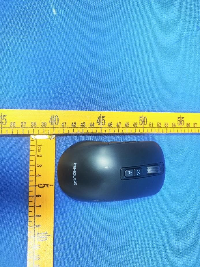
Click to zoom
Application Details
- Equipment Class
- DTS - Digital Transmission System
- Date of Grant
- Mar 25, 2024
- Application Purpose
- Original Equipment
- Date of Application
- Mar 25, 2024
- Equipment Note
- AI Mouse
- Frequency Range
- 2402.00000000 - 2480.00000000
- Country
- China
Documents & Files
Document Text
Text extracted from the exhibit documents filed with the FCC. Open a document above to read the original.
Users Manual
INSTRUCTION MANUAL MiMouse EM4 AI Important Notes -P le ase read the instruc tio ns caref ull y bef ore using this produc t. -To ensure your safety, please read the precautions carefully before using this product. Product IntroductionWindows PC Installation Tutorial Turn on the mouse power switch, take out the receiver and plug it into the USB interface of the computer. Name Size Weight Charging port Type DPI resolution Battery capacity Support system (Compatible with) MiMouse EM4 AI Model AI mouse 120mmx65mmx37mm 92g Type-C 2.4G Wireless; Buletooth 800-4000DPI multi-speed adjustable 600mAh (Lithium-ion battery) Windows 7/8/10/11, MacOS 10.15 and above (Bluetooth connection does not support windows7 operating system for the time being; Apple's system currently only supports some functions) Packing List Mouse 1EA Receiver 1EA Charging Cable 1EA Manual 1EA Specification Power switch BT1 BT2 ON OFF Power switch BT1 BT2 ON OFF Speech button Translation button Right-clickLeft-click Scroll wheel Long press: speech typing Long press: speech translation Clic k: word translation Long pres s: smart writi ng Clic k: enter AI interface OCR button AI button BT1 BT2 ON OFF Type-C Charging port DC 5V-1A power supply charging Power switch Receiver Mode indicator light Mode switch Key Receiver connection:red light Bluetooth 1 connection:blue light Bluetooth 2 connection:purple light Short press:mode switch Long press:enter bluetooth pairing For the first time, press the mouse "Speech button" for 3 seconds, and the computer will automatically open the driver download page, select windows system software download, and the installation is completed. Use smart features. AI button, long press: smart writing, click: enter AI interface. Warning note Charging instructions Safety Precautions . If the battery is used improperly, it can lead to leakage, explosions, and other incidents, resulting in personal injury or fire. . Do not expose it to humid or high-temperature environments, and avoid contact with conductive materials or liquids. . It is recommended to use a charger marked "Output 5V-1A" for charging; When charging, keep this product away from heat sources such as heating equipment. . Do not disassemble, repair or modify this product yourself. . When using the product indicator lights, please avoid getting close to the eyes of children or animals. . It is recommended to connect the mouse charging cable to the computer for charging. Click the 'AI button' to automatically download the M-AI software,wait for the download to complete, and follow the steps to click Install. Mode indicator Charging indicator Indicator Description Pairing/low power indicator Charging Low battery Pairing Mode Note · Use the included 5V-1A charger for charging. . You can check the mouse battery level in the Mimouse Driver software interface. The charging red light remains constant, turns off when fully charged. If the battery is below 20%, the blue light will slowly flash as the mouse is powered on/woken up, and it will turn off after 30 seconds. Red light indicates receiver connection; Blue light indicates Bluetooth 1 connection; Purple light indicates Bluetooth 2 connection. The blue light rapidly flashes while waiting for pairing and turns off after pairing or timing out. BT1 BT2 ON OFF BT1 BT2 ON OFF Short press the 'mode Long press the 'mode switch button' for 3 seconds The indicator flashes rapidly, indicating it is waiting for pairing. switch button' Bluetooth Connection Method Mode indicator light BT1 BT2 ON OFF Press the 'Mode switch button' briefly to switch to Bluetooth 1 or Bluetooth 2, and the upper status indicator will be blue or purple. Long press the 'Mode switch button' for 3 seconds, and the blue light at the rear of the mouse will flash rapidly, indicating it is waiting for Bluetooth pairing. Turn on your computer's Bluetooth, search for and connect to EM4 AI. Note: Mouse bluetooth connection is not supported on the windows 7 operating system. FCC Caution. This device complies with part 15 of the FCC Rules. Operation is subject to the following two conditions: (1) This device may not cause harmful interference, and (2) this device must accept any interference received, including interference that may cause undesired operation. Any Changes or modifications not expressly approved by the party responsible for compliance could void the user's authority to operate the equipment. Note: This equipment has been tested and found to comply with the limits for a Class B digital device, pursuant to part 15 of the FCC Rules. These limits are designed to provide reasonable protection against harmful interference in a residential installation. This equipment generates uses and can radiate radio frequency energy and, if not installed and used in accordance with the instructions, may cause harmful interference to radio communications. However, there is no guarantee that interference will not occur in a particular installation. If this equipment does cause harmful interference to radio or television reception, which can be determined by turning the equipment off and on, the user is encouraged to try to correct the interference by one or more of the following measures: -Reorient or relocate the receiving antenna. -Increase the separation between the equipment and receiver. -Connect the equipment into an outlet on a circuit different from that to which the receiver is connected. -Consult the dealer or an experienced radio/TV technician for help. *RF warning for Portable device: The device has been evaluated to meet general RF exposure requirement. The device can be used in portable exposure condition without restriction. Press the ‘Mode switch button’ to switch between three computers Connect three computers The first computer The second computer The third computer Receiver Bluetooth 1 Bluetooth 2 ComputerConnection method Mac PC Installation Tutorial Turn on the mouse power switch, take out the receiver and plug it into the USB in…
Text truncated - open the document above for the full version.
External Photos
FCC ID: 2BE8P-EM4AI FCC ID: 2BE8P-EM4AI FCC ID: 2BE8P-EM4AI FCC ID: 2BE8P-EM4AI
ID Label/Location Info
FCC ID: 2BE8P-EM4AI FCC ID: 2BE8P-EM4AI
Internal Photos
FCC ID: 2BE8P-EM4AI FCC ID: 2BE8P-EM4AI FCC ID: 2BE8P-EM4AI FCC ID: 2BE8P-EM4AI FCC ID: 2BE8P-EM4AI ANT
RF Exposure Info
Page1of3 RFEXPOSUREEVALUATION FCCID:2BE8P-EM4AI ProductName: AIMouse ModelName: EM4AI BluetoothVersion:BT5.0 Operatingfrequency:2402-2480MHz NumbersofChannel: 40channelsForDTS 16channelsforSRD AntennaType:PCBAntenna AntennaGain:0.72dBi TypeofModulation:GFSK Powersupply: Input:DC5V0.5A2.5W Output:DC3V50mA,0.2W Li-ionBattery:YJ602540 Voltage:3.7VCapacity:600mAh LimitedChargeVoltage:4.2V HardwareVersion:N/A SoftwareVersion:N/A Page2of3 StandardRequirement Accordingto§15.247(i)and§1.1307b(1),systemsoperatingundertheprovisionsofthis sectionshallbeoperatedinamannerthatensuresthatthepublicisnotexposedtoradio frequencyenergylevelsinexcessoftheCommission’sguidelines.SeeKDB447498D01 GeneralRFExposureGuidancev06,section4.3.1. The1-gand10-gSARtestexclusionthresholdsfor100MHzto6GHzattestseparation distances≤50mmaredeterminedby: [(max.powerofchannel,includingtune-uptolerance,mW)/(min.testseparationdistance, mm)]*[√f(GHz)]≤3.0for1-gSARand≤7.5for10-gSARextremitySAR,where f(GHz)istheRFchanneltransmitfrequencyinGHz PoweranddistanceareroundedtothenearestmWandmmbeforecalculation Theresultisroundedtoonedecimalplaceforcomparison. Thetestexclusionsareapplicableonlywhentheminimumtestseparationdistanceis≤ 50mmandfortransmissionfrequenciesbetween100MHzand6GHz.Whentheminimumtest separationdistanceis<5mm,adistanceof5mmisappliedtodetermineSARtestexclusion. RoutineSARevaluationreferstothatspecificallyrequiredby§2.1093,usingmeasurements orcomputersimulation.WhenroutineSARevaluationisnotrequired,portabletransmitters withoutputpowergreaterthantheapplicablelowthresholdrequireSARevaluationtoquality forTCBapproval. RFOutputpower Freq. (MHz) Fieldstrength(max)(dBuV/m) EIRP(max) (dBm) 243893.31-1.89 Note:EIRP=E-104.8+20logD, Where EistheelectricfieldstrengthindBμV/m. EIRPistheequivalentisotropicallyradiatedpowerindBm. disthespecifiedmeasurementdistanceinm. whereD=3,EIRP=E-95.2. Page3of3 Channel (MHz) Maximum output power (dBm) Tuneup tolerance (dBm) MaxTune UpPower (mW) Distance (mm) Calculation results Limit Operating Mode 24807.347.34 ± 16.82338752.1490963BLE_1M 2480-1.89-1.89±10.83176450.2619733SRD AccordingtoKDB447498,nostand-alonerequiredforBTantenna,andnosimultaneousSAR measurementisrequired. Signature SimonPu Manager Date:2024-03-20
Test Report
Page 1 of 10 Antenna REPORT Product : AI Mouse Model Name : EM4 AI Applicant’s name : Anhui MiMouse Technology Co., Ltd Address : 7th Floor, Building J4, Zhong'an Chuanggu Phase II, Shushan District, Hefei City, Anhui Province Page 2 of 10 Contents 1 Test Summary .......................................................................................................................................................................... 3 2 EUT Description ....................................................................................................................................................................... 4 3 Test Data .................................................................................................................................................................................... 5 3.1 Typical free space efficiency and gain ............................................................................................................... 5 3.2 Typical free space radiation pattern ................................................................................................................... 6 3.3 3D Pattern.................................................................................................................................................................... 8 4 EUT appearance .................................................................................................................................................................... 10 Page 3 of 10 1 Test Summary Name Parameter Method Standard no. Mobile communication antenna Antenna gain Generic specification for antennas used in the mobile communications GB/T 9410-2008 Radiation pattern Antenna Radiation efficiency IEEE Standard Test Procedures for Antennas ANSI/IEEE Std 149-1979 Gain and directivity Page 4 of 10 2 EUT Description Product Name AI Mouse Sample Model EM4 AI Size / Test Item Antenna gain; Radiation pattern and efficiency Antenna Type PCB Antenna Frequency Range 2400MHz-2500MHz Page 5 of 10 3 Test Data 3.1 Typical free space efficiency and gain Frequency/MHz Efficiency / dB Efficiency / % Max Gain/dBi Avg Gain/dBi 2400 -3 50.12 0.72 -3 2410 -2.92 51.05 0.64 -2.92 2420 -2.98 50.35 0.25 -2.98 2430 -2.93 50.93 0.02 -2.93 2440 -2.91 51.17 -0.26 -2.91 2450 -2.94 50.82 -0.63 -2.94 2460 -3.2 47.86 -0.84 -3.2 2470 -3.34 46.34 -0.99 -3.34 2480 -3.4 45.71 -0.91 -3.4 2490 -3.56 44.06 -0.93 -3.56 2500 -3.76 42.07 -1.08 -3.76 Page 6 of 10 3.2 Typical free space radiation pattern (1) X-Z Plane: V Phi=0 (2) Y-Z Plane: V Phi=90 Page 7 of 10 (3)X-Y Plane: H Theta=90 page 8 of 10 3.3 3D Pattern 3D Pattern for 2400MHz 3D Pattern for 2450MHz page 9 of 10 3D Pattern for 2500MHz Page 10 of 10 4 EUT appearance ******THE END REPORT******
Test Report
Page1of65 FCCTESTREPORT FCCID:2BE8P-EM4AI Product: AIMouse ModelName:EM4AI Brand: mimouse ReportNo.: PTC24012508301E-FC02 Preparedfor AnhuiMiMouseTechnologyCo.,Ltd 7thFloor,BuildingJ4,Zhong'anChuangguPhaseII,ShushanDistrict,HefeiCity,Anhui Province Preparedby PreciseTesting&CertificationCo.,Ltd Building1,No.6,TongxinRoad,DongchengStreet,Dongguan,Guangdong,China ReportNo.:PTC24012508301E-FC02 Page2of65 1TESTRESULTCERTIFICATION Applicant’sname:AnhuiMiMouseTechnologyCo.,Ltd Address: 7thFloor,BuildingJ4,Zhong'anChuangguPhaseII,ShushanDistrict, HefeiCity,AnhuiProvince Manufacture'sname:AnhuiMiMouseTechnologyCo.,Ltd Address: 7thFloor,BuildingJ4,Zhong'anChuangguPhaseII,ShushanDistrict, HefeiCity,AnhuiProvince Productname:AIMouse Modelname:EM4AI Standards:FCCCFR47Part15Section15.247 Testprocedure:ANSIC63.10:2013 TestDate: Feb.26,2024toMar.13,2024 DateofIssue: Mar.20,2024 TestResult:Pass ThisdevicedescribedabovehasbeentestedbyPTC,andthetestresultsshowthatthe equipmentundertest(EUT)isincompliancewiththeFCCrequirements.Anditisapplicableonlyto thetestedsampleidentifiedinthereport. Thisreportshallnotbereproducedexceptinfull,withoutthewrittenapprovalofPTC,thisdocument maybealteredorrevisedbyPTC,personalonly,andshallbenotedintherevisionofthedocument. TestEngineer: Jackzhou/Engineer TechnicalManager: SimonPu/Manager ReportNo.:PTC24012508301E-FC02 Page3of65 Contents Page 1TESTRESULTCERTIFICATION.........................................................................................................................2 2TESTSUMMARY..........................................................................................................................................................5 2.1TESTSITE............................................................................................................................................................6 3GENERALINFORMATION......................................................................................................................................7 3.1GENERALDESCRIPTIONOFE.U.T....................................................................................................................7 3.2CHANNELLIST.....................................................................................................................................................8 4EQUIPMENTDURINGTEST...................................................................................................................................9 4.1EQUIPMENTSLIST.............................................................................................................................................9 4.2MEASUREMENTUNCERTAINTY.........................................................................................................................11 4.3DESCRIPTIONOFSUPPORTUNITS...................................................................................................................12 5CONDUCTEDEMISSION..........................................................................................................................................13 5.1E.U.T.OPERATION...........................................................................................................................................13 5.2EUTSETUP.......................................................................................................................................................13 5.3TESTSET-UP(BLOCKDIAGRAMOFCONFIGURATION)................................................................................14 5.4MEASUREMENTPROCEDURE...........................................................................................................................14 5.5CONDUCTEDEMISSIONLIMIT...........................................................................................................................14 5.6MEASUREMENTDESCRIPTION..........................................................................................................................14 5.7CONDUCTEDEMISSIONTESTRESULT.............................................................................................................14 6RADIATEDSPURIOUSEMISSIONS......................................................................................................................17 6.1EUTOPERATION...............................................................................................................................................17 6.2TESTSETUP......................................................................................................................................................18 6.3SPECTRUMANALYZERSETUP.........................................................................................................................19 6.4TESTPROCEDURE.............................................................................................................................................20 6.5SUMMARYOFTESTRESULTS..........................................................................................................................22 7CONDUCTBANDEDGEANDSPURIOUSEMISSIONSMEASUREMENT....................................................29 7.1TESTPROCEDURE.............................................................................................................................................29 7.2TESTRESULT....................................................................................................................................................30 86DBBANDWIDTHMEASUREMENT......................................................................................................................43 ReportNo.:PTC24012508301E-FC02 Page4of65 TESTPROCEDURE...................................................................................................................................................43 TESTRESULT......................................................................................................................................................…
Text truncated - open the document above for the full version.
Test Report
ReportNo.:PTC24012508301E-FC02 Page46of65 BLE_2M-Ant1-2440-PASS BLE_2M-Ant1-2480-PASS ReportNo.:PTC24012508301E-FC02 Page47of65 9MaximumPeakOutputPower TestRequirement:FCCCFR47Part15Section15.247 TestMethod:ANSIC63.10:2013 TestLimit: Regulation15.247(b)(3),Forsystemsusingdigitalmodulationinthe 902-928MHz,2400-2483.5MHz,and5725-5850MHzbands:1Watt.As analternativetoapeakpowermeasurement,compliancewiththeone Wattlimitcanbebasedonameasurementofthemaximumconducted outputpower. 9.1TestProcedure 1.TheRFoutputofEUTwasconnectedtothespectrumanalyzerbyRFcableandattenuator.The pathlosswascompensatedtotheresultsforeachmeasurement. 2.SettothemaximumpowersettingandenabletheEUTtransmitcontinuously. 3.Measuretheconductedoutputpowerandrecordtheresultsinthetestreport. 9.2TestSetup 9.3TestResult TestModeAntennaFrequency[MHz] ConductedPeak Powert[dBm] Conducted Limit[dBm] Verdict BLE_1MAnt124025.23≤30PASS BLE_1MAnt124406.02≤30PASS BLE_1MAnt124807.34≤30PASS BLE_2MAnt124024.91≤30PASS BLE_2MAnt124405.52≤30PASS BLE_2MAnt124806.79≤30PASS ReportNo.:PTC24012508301E-FC02 Page48of65 TestGraphs: BLE_1M-Ant1-2402-PASS BLE_1M-Ant1-2440-PASS ReportNo.:PTC24012508301E-FC02 Page49of65 BLE_1M-Ant1-2480-PASS BLE_2M-Ant1-2402-PASS ReportNo.:PTC24012508301E-FC02 Page50of65 BLE_2M-Ant1-2440-PASS BLE_2M-Ant1-2480-PASS ReportNo.:PTC24012508301E-FC02 Page51of65 10PowerSpectraldensity TestRequirement:FCCCFR47Part15Section15.247 TestMethod:ANSIC63.10:2013 TestLimit:Regulation15.247(f)Thepowerspectraldensityconductedfromthe intentionalradiatortotheantennaduetothedigitalmodulation operationofthehybridsystem,withthefrequencyhoppingoperation turnedoff,shallnotbegreaterthan8dBminany3kHzbandduring anytimeintervalofcontinuoustransmission. 10.1TestProcedure 1.RemovetheantennafromtheEUTandthenconnectalowRFcablefromtheantennaporttothe spectrum. 2.Setthespectrumanalyzer:RBW=3kHz.VBW=10kHz,Span=1.5timestheDTSchannelbandwidth(6 dBbandwidth).Sweep=auto;DetectorFunction=Peak.Trace=Maxhold. 3.Allowthetracetostabilize.Usethemarker-deltafunctiontodeterminetheseparationbetweenthepeaksof theadjacentchannels.ThelimitisspecifiedinoneofthesubparagraphsofthisSectionSubmitthisplot. 10.2TestSetup 10.3TestResult TestModeAntennaFrequency[MHz]Result[dBm/3kHz]Limit[dBm/3kHz]Verdict BLE_1MAnt12402-4.34≤8.00PASS BLE_1MAnt12440-4.23≤8.00PASS BLE_1MAnt12480-2.65≤8.00PASS BLE_2MAnt12402-7.86≤8.00PASS BLE_2MAnt12440-7.81≤8.00PASS BLE_2MAnt12480-5.78≤8.00PASS ReportNo.:PTC24012508301E-FC02 Page52of65 TestGraphs: BLE_1M-Ant1-2402-PASS BLE_1M-Ant1-2440-PASS ReportNo.:PTC24012508301E-FC02 Page53of65 BLE_1M-Ant1-2480-PASS BLE_2M-Ant1-2402-PASS ReportNo.:PTC24012508301E-FC02 Page54of65 BLE_2M-Ant1-2440-PASS BLE_2M-Ant1-2480-PASS ReportNo.:PTC24012508301E-FC02 Page55of65 11AntennaApplication 11.1AntennaRequirement Forintentionaldevice,accordingtoFCC47CFRSection15.203,anintentional radiatorshallbedesignedtoensurethatnoantennaotherthanthatfurnishedbythe responsiblepartyshallbeusedwiththedevice.AndaccordingtoFCC47CFRSection 15.247(b),iftransmittingantennasofdirectionalgaingreaterthan6dBiareused,the powershallbereducedbytheamountindBthatthedirectionalgainoftheantenna exceeds6dBi. 11.2Result TheEUT’Santenna,permanentattachedantenna,isinternalPCBantenna.The antenna’sgainis0.72dBiandmeetstherequirement. ReportNo.:PTC24012508301E-FC02 Page56of65 12TestSetup ConductedEmissions RadiatedSpuriousEmissions TestFrequencyFromBelow30MHz ReportNo.:PTC24012508301E-FC02 Page57of65 TestfrequencyfromAbove1GHz ReportNo.:PTC24012508301E-FC02 Page58of65 13EUTPhotos ReportNo.:PTC24012508301E-FC02 Page59of65 ReportNo.:PTC24012508301E-FC02 Page60of65 ReportNo.:PTC24012508301E-FC02 Page61of65 ReportNo.:PTC24012508301E-FC02 Page62of65 ReportNo.:PTC24012508301E-FC02 Page63of65 ReportNo.:PTC24012508301E-FC02 Page64of65 ReportNo.:PTC24012508301E-FC02 Page65of65 ******THEENDREPORT******
Test Setup Photos
FCCID:2BE8P-EM4AI ConductedEmissions RadiatedSpuriousEmissions From30MHz-1000MHz FCCID:2BE8P-EM4AI Testfrequencyfrom1GHz
Contact Information
Applicant
Guoran Zhu(Technician)
Test Firm
Precise Testing & Certification Co., LTD.Chris Du
[email protected]+86-769-38808222
Technical Specifications
| # | Rule Parts | Frequency Range | Power Output |
|---|---|---|---|
| 1 | 15C | 2.40 GHz - 2.48 GHz | 5.40 mW |