2BE9L-PHRONESISVirtusx AI Keyboard
MOUNT ZION INNOVATION LLC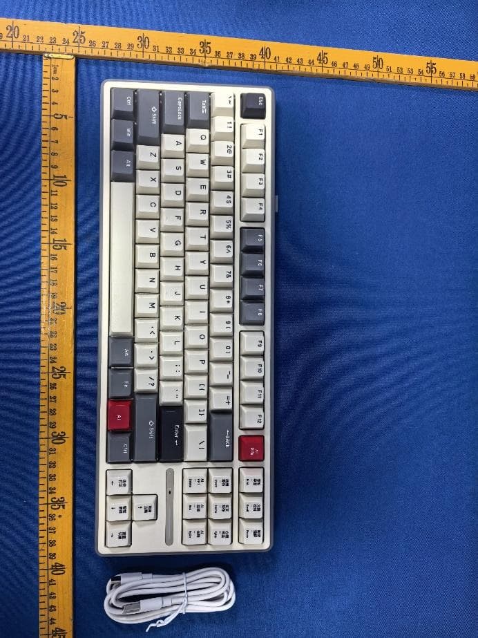
Click to zoom
Application Details
- Equipment Class
- DTS - Digital Transmission System
- Date of Grant
- Dec 11, 2025
- Application Purpose
- Original Equipment
- Equipment Note
- Virtusx AI Keyboard
- Frequency Range
- 2402.00000000 - 2480.00000000
- Company
- MOUNT ZION INNOVATION LLC
- Country
- United States
Documents & Files
Document Text
Text extracted from the exhibit documents filed with the FCC. Open a document above to read the original.
Users Manual
成品尺寸:100*170mm(±1.5mm) 材质:105g铜版纸,双面彩印,风琴折页 Mode Switcher USB Receiver Charging/Wired Mode Connection Port Connect AI Keyboard to ComputerVirtusx V-AI Software InstallationDevice Overview Windows PC Installation Wired Connection AI Button Description Indicator Light DescriptionsProduct SpecificationsProblem TroubleshootingCertificationWarranty Policy Learn More Virtusx Al Keyboard Phronesis Instruction Manual · Middle: Wired mode · Right: 2.4G USB Receiver Mode Connect the USB-C cable to the computer and set the mode switcher to the middle for wired mode. Set the mode switcher to the right for 2.4G USB Receiver Mode. Remove the USB receiver from the back of the keyboard and plug it into the computer’s USB port. · Visit our official website: www.virtusxus.com. · Navigate to the Software tab. · Select Download for Windows. · Install the software. It should automatically open upon successful installation. Note: If you use McAfee or Norton antivirus software, you may see a warning during installation. Please approve the installation to proceed. MacOS Installation · Visit our official website: www.virtusxus.com. · Navigate to the Software tab. · Select Download for MacOS. · Double-click the downloaded file and drag the V-AI icon into your Applications folder to install. · After installation, open System Settings and go to Privacy & Security. · Enable the V-AI software under the following sections: 1. Accessibility 2. Input Monitoring 3. Screen Recording & System Audio Recording Note: Once these settings are enabled, all AI features will function seamlessly on your MacOS system. For a step-by-step tutorial, watch the video. Connection TypeMode Switcher Setting The mode switcher is in the middle position. The mode switcher is set to the right for 2.4G. Wired Mode Receiver Mode IndicatorDescription Backlighting turns white when in AI mode. While charging, the right side flashes blue three times. When fully charged, it flashes green three times. When the battery is low, the bottom right of the keyboard flashes red and turns off after 30 seconds. Press and hold Fn + Enter to check the battery level when the USB receiver is connected. Each lit key represents the battery percentage: · Key 1 lit: Battery is at 10%. · Keys 1 and 2 lit: Battery is at 20%. · Keys 1-10 lit: Battery is at 100%. AI Mode Indicator Charging Indicator Low Battery Indicator Battery Indicator TimeframeAction Eligible for free return or replacement unit Eligible for free replacement unit Eligible for free repair services Within the first 7 days of receiving the product From day 8 to 30 after receiving the product Within the initial 12 months of receiving the product Eligible for Warranty: · Product must be sold by Virtusx with a purchase history. · Confirmed performance issues in "Product Performance Failure Table" by Virtus customer service. Not Eligible for Warranty: · Software, encompassing (but not limited to) (i) the operating system and software integrated into Virtusx-branded hardware products through our factory-integration system, ii) third-party software, or (iii) the reloading of software, software configurations, or any data files. · Claims arising from unacceptable use or care of the Product, including misuse, abuse, negligence, unauthorized modification or repair, unauthorized commercial use, or any operation of the Product beyond Virtusx's recommended parameters. · Claims arising from external causes, such as accidents, acts of nature, liquid contact, fire, or earthquake. · Cosmetic damage, minor cosmetic abnormalities, and normal wear and tear, including scratches, dents, and chips. · Products with a serial number or date stamp that have been altered, obliterated, or removed. · Products not sold by Virtus with no purchase history or from unauthorized third-party sellers. Friendly Reminder: NamePerformance Failures Damage from structural or material issues caused by manufacturing factors Indicator not lighting up Keyboard not functioning normally Virtusx AI Keyboard Product Performance Failure Table For secure product shipping during exchanges, it is recommended to keep the box for a minimum of 30 days from the date of purchase. Re-pairing steps for the USB receiver when not connecting properly Switch the mode switcher to receiver mode. Press and hold Fn + P until the P button flashes quickly with a white backlight, entering pairing mode. Plug the USB receiver into the computer’s USB port, the backlight will turn off once the connection is successful. Safety Guidelines Warning · Improper use of the battery may cause leaks, explosions, and other incidents, posing a risk of personal injury or fire. · Keep away from humidity, high temperatures, and contact with conducive materials or liquids. · Do not disassemble, repair, or modify this product yourself. Charging Instructions · It is recommended to connect the keyboard charging cable to the computer for charging. · Use the provided data cable or one label “Output 5V-1A” for charging. · Keep this product away from heat sources like heating appliance or direct sunlight during charging. FCC Caution: This device complies with part 15 of the FCC rules. Operation is subject to two conditions: (1) it may not cause harmful interference, and (2) it must accept any interference received, including interference that may cause undesired operation. Unauthorized changes or modifications could void the user's authority to operate the equipment. Note: This equipment complies with Class B digital device limits under part 15 of the FCC Rules, designed to provide reasonable protection against harmful interference in residential installations. It generates, uses, and can radiate radio frequency energy. If not installed and used according to the instructions, it may cause harmful interference to radio communications. There is no guarantee interference will not occur in a particular installation. If it does, try the following: · Reorient or relocate the receiving antenna. · Increase the d…
Text truncated - open the document above for the full version.
Attestation Statements
MOUNT ZION INNOVATION LLC (December 2, 2025) TO: Federal Communications Commission Authorization and Evaluation Division 7435 Oakland Mills Road Columbia, MD 21046, USA RE: Attestation Statements Part 2.911(d)(7) request for (FCC ID: 2BE9L-PHRONESIS) (MOUNT ZION INNOVATION LLC), the undersigned, hereby authorize MOUNT ZION INNOVATION LLC to act as our designated U.S. agent for service of process, (MOUNT ZION INNOVATION LLC) accepts to maintain an agent for no less than one year after the grantee has terminated all marketing and importation or the conclusion of any Commission-related proceeding involving the equipment. MOUNT ZION INNOVATION LLC accepts the responsibility to act as designated U.S. agent for service of process. Applicant Information: Company Name: MOUNT ZION INNOVATION LLC Contact Name: Jerry Hsu Address: 10412 W 131st Street, Overland Park, Kansas, 66213 United States FRN: 0035057967 Telephone No: 720-234-2086 Email: [email protected] Signature [Jerry Hsu] U.S. Agent Information: Company Name: MOUNT ZION INNOVATION LLC Address: 10412 W 131st Street, Overland Park, Kansas, 66213 United States FRN: 0035057967 Contact Name: Jerry Hsu Telephone No: 720-234-2086 Email: [email protected] Signature [Jerry Hsu]
External Photos
FCCID:2BE9L-PHRONESIS FCCID:2BE9L-PHRONESIS FCCID:2BE9L-PHRONESIS FCCID:2BE9L-PHRONESIS
ID Label/Location Info
LabelandLabelLocation
Internal Photos
FCCID:2BE9L-PHRONESIS FCCID:2BE9L-PHRONESIS FCCID:2BE9L-PHRONESIS FCCID:2BE9L-PHRONESIS FCCID:2BE9L-PHRONESIS FCCID:2BE9L-PHRONESIS FCCID:2BE9L-PHRONESIS ANT FCCID:2BE9L-PHRONESIS FCCID:2BE9L-PHRONESIS
RF Exposure Info
Page 1 of 3 RF EXPOSURE EVALUATION FCC ID: 2BE9L-PHRONESIS Product Name : Virtusx AI Keyboard Model Name : Phronesis Bluetooth Version : BT 5.0 Operating frequency : 2402-2480MHz Numbers of Channel : 40 channels for DTS 40 channels for 2.4G SRD Antenna Type : PCB antenna Antenna Gain : 0.72 dBi Type of Modulation : GFSK Power supply : Input: DC 5V⎓1.2A Li-ion Battery : 5543120 Rated Voltage: 3.7V Capacity:3750mAh 13.875Wh Hardware Version : V4.1 Software Version : V1.1.3.1 Page 2 of 3 Standard Requirement According to § 15.247(i) and § 1.1307b(1), systems operating under the provisions of this section shall be operated in a manner that ensures that the public is not exposed to radio frequency energy levels in excess of the Commission’s guidelines. See KDB 447498 D01 General RF Exposure Guidance v06, section 4. 3. 1. The 1-g and 10-g SAR test exclusion thresholds for 100MHz to 6GHz at test separation distances ≤ 50mm are determined by: [ (max. power of channel, including tune-up tolerance, mW)/(min. test separation distance, mm)]*[ √f(GHz)] ≤3.0 for 1-g SAR and ≤7.5 for 10-g SAR extremity SAR, where ⚫ f(GHz) is the RF channel transmit frequency in GHz ⚫ Power and distance are rounded to the nearest mW and mm before calculation ⚫ The result is rounded to one decimal place for comparison. The test exclusions are applicable only when the minimum test separation distance is ≤ 50mm and for transmission frequencies between 100MHz and 6GHz. When the minimum test separation distance is <5mm, a distance of 5mm is applied to determine SAR test exclusion. Routine SAR evaluation refers to that specifically required by § 2.1093, using measurements or computer simulation. When routine SAR evaluation is not required, portable transmitters with output power greater than the applicable low threshold require SAR evaluation to quality for TCB approval. RF Output power Freq. (MHz) Field strength(max)(dBuV/m) EIRP (max) (dBm) 2480(BLE_1M) 94.02 -1.18 Note: EIRP=E-104.8+20logD, Where E is the electric field strength in dBμV/m. EIRP is the equivalent isotropically radiated power in dBm. d is the specified measurement distance in m. where D=3, EIRP=E-95.2. Page 3 of 3 Channel (MHz) Maximum output power (dBm) Tune up tolerance (dBm) Max Tune Up Power (mW) Distance( mm) Calculation results Limit Operating Mode 2480 -1.18 -1.18±1 0.959401 5 0.302173 3 GFSK_1Mbps 2480 7.11 7.11±1 6.471426 5 2.038242 3 BLE_1M According to KDB 447498, The device support BT and 2.4G SRD function, BT and 2.4G SRD cannot be transmitted simultaneously, and no simultaneous SAR measurement is required. Signature Simon Pu Manager Date: 2025-12-02
Test Report
Page 1 of 71 FCC TEST REPORT FCC ID: 2BE9L-PHRONESIS Product : Virtusx AI Keyboard Model Name : Phronesis Brand : Virtusx Report No. : PTC25101619401E-FC02 Prepared for MOUNT ZION INNOVATION LLC 10412 W 131st Street, Overland Park, KS 66213 Prepared by Precise Testing & Certification Co., Ltd Building 1, No. 6, Tongxin Road, Dongcheng Street, Dongguan, Guangdong, China Report No.: PTC25101619401E-FC02 Page 2 of 71 1 TEST RESULT CERTIFICATION Applicant’s name : MOUNT ZION INNOVATION LLC Address : 10412 W 131st Street, Overland Park, KS 66213 Manufacture's name : MOUNT ZION INNOVATION LLC Address : 10412 W 131st Street, Overland Park, KS 66213 Product name : Virtusx AI Keyboard Model name : Phronesis Standards : FCC CFR47 Part 15 Section 15.247 Test procedure : ANSI C63.10-2020 Test Date : Dec. 31, 2025 to Nov. 19, 2025 Date of Issue : Dec. 02, 2025 Test Result : Pass This device described above has been tested by PTC, and the test results show that the equipment under test (EUT) is in compliance with the FCC requirements. And it is applicable only to the tested sample identified in the report. This report shall not be reproduced except in full, without the written approval of PTC, this document may be altered or revised by PTC, personal only, and shall be noted in the revision of the document. Test Engineer: Jack zhou / Engineer Technical Manager: Simon Pu / Manager Report No.: PTC25101619401E-FC02 Page 3 of 71 Contents Page 1 TEST RESULT CERTIFICATION .............................................................................................................................. 2 2 TEST SUMMARY ......................................................................................................................................................... 5 2.1 TEST SITE ........................................................................................................................................................... 6 3 GENERAL INFORMATION ..................................................................................................................................... 7 3.1 GENERAL DESCRIPTION OF E.U.T. .................................................................................................................... 7 3.2 CHANNEL LIST .................................................................................................................................................... 8 4 EQUIPMENT DURING TEST .................................................................................................................................. 9 4.1 EQUIPMENTS LIST ............................................................................................................................................ 9 4.2 MEASUREMENT UNCERTAINTY ......................................................................................................................... 11 4.3 DESCRIPTION OF SUPPORT UNITS ................................................................................................................... 12 5 CONDUCTED EMISSION ......................................................................................................................................... 13 5.1 E.U.T. OPERATION ........................................................................................................................................... 13 5.2 EUT SETUP ...................................................................................................................................................... 13 5.3 TEST SET-UP (BLOCK DIAGRAM OF CONFIGURATION) .................................................................................. 14 5.4 MEASUREMENT PROCEDURE ........................................................................................................................... 14 5.5 CONDUCTED EMISSION LIMIT ........................................................................................................................... 14 5.6 MEASUREMENT DESCRIPTION .......................................................................................................................... 14 5.7 CONDUCTED EMISSION TEST RESULT ............................................................................................................. 14 6 RADIATED SPURIOUS EMISSIONS ..................................................................................................................... 17 6.1 EUT OPERATION .............................................................................................................................................. 17 6.2 TEST SETUP ..................................................................................................................................................... 18 6.3 SPECTRUM ANALYZER SETUP .......................................................................................................................... 19 6.4 TEST PROCEDURE ............................................................................................................................................ 20 6.5 SUMMARY OF TEST RESULTS .......................................................................................................................... 22 7 CONDUCT BAND EDGE AND SPURIOUS EMISSIONS MEASUREMENT ................................................... 30 7.1 TEST PROCEDURE ............................................................................................................................................ 30 7.2 TEST SETUP ..................................................................................................................................................... 30 7.3 TEST RESULT ................................................................................................................................................... 31 Report No.: PTC25101619401E-FC02 Page 4 of 71 8 6DB BANDWIDTH MEASUREMENT ........................................................................…
Text truncated - open the document above for the full version.
Test Report
Page 1 of 10 Antenna REPORT Product : Model Name : Applicant’s name : PCB antenna MK87 Address : Anhui MiMouse Technology Co., Ltd Room 701, Building J4, Phase II, Zhong'an Innovation Valley Science and Technology Park, No. 920 Wangjiang West Road, Hefei High-tech Development Zone Page 2 of 10 Contents 1 Test Summary .......................................................................................................................................................................... 3 2 EUT Description ....................................................................................................................................................................... 4 3 Test Data .................................................................................................................................................................................... 5 3.1 Typical free space efficiency and gain ............................................................................................................... 5 3.2 Typical free space radiation pattern ................................................................................................................... 6 3.3 3D Pattern.................................................................................................................................................................... 8 4 EUT appearance .................................................................................................................................................................... 10 Page 3 of 10 1 Test Summary Name Parameter Method Standard no. Mobile communication antenna Antenna gain Generic specification for antennas used in the mobile communications GB/T 9410-2008 Radiation pattern Antenna Radiation efficiency IEEE Standard Test Procedures for Antennas ANSI/IEEE Std 149-1979 Gain and directivity Page 4 of 10 2 EUT Description Product Name PCB antenna Sample Model MK87 Size / Test Item Antenna gain; Radiation pattern and efficiency Antenna Type PCB Antenna Frequency Range 2400MHz-2500MHz Page 5 of 10 3 Test Data 3.1 Typical free space efficiency and gain Frequency/MHz Efficiency / dB Efficiency / % Max Gain/dBi Avg Gain/dBi 2400 -3 50.12 0.72 -3 2410 -2.92 51.05 0.64 -2.92 2420 -2.98 50.35 0.25 -2.98 2430 -2.93 50.93 0.02 -2.93 2440 -2.91 51.17 -0.26 -2.91 2450 -2.94 50.82 -0.63 -2.94 2460 -3.2 47.86 -0.84 -3.2 2470 -3.34 46.34 -0.99 -3.34 2480 -3.4 45.71 -0.91 -3.4 2490 -3.56 44.06 -0.93 -3.56 2500 -3.76 42.07 -1.08 -3.76 Page 6 of 10 3.2 Typical free space radiation pattern (1) X-Z Plane: V Phi=0 (2) Y-Z Plane: V Phi=90 Page 7 of 10 (3)X-Y Plane: H Theta=90 page 8 of 10 3.3 3D Pattern 3D Pattern for 2400MHz 3D Pattern for 2450MHz page 9 of 10 3D Pattern for 2500MHz Page 10 of 10 4 EUT appearance ******THE END REPORT******
Test Setup Photos
Report No.: PTC25101619401E-FC02 Page 57 of 71 12 Test Setup Conducted Emissions Radiated Spurious Emissions Test Frequency From 30MHz to 1GHz Report No.: PTC25101619401E-FC02 Page 58 of 71 Test frequency from Above 1GHz
Contact Information
Applicant
Jerry Hsu(COO)
[email protected]Fax: 913 828-6870
Test Firm
Precise Testing & Certification Co., LTD.Yang Juan
Technical Specifications
| # | Rule Parts | Frequency Range | Power Output |
|---|---|---|---|
| 1 | 15C | 2.40 GHz - 2.48 GHz | 5.10 mW |