2BECQ-MC82Smart thermometer
Dongguan Jinghe Electronic Technology Co., Ltd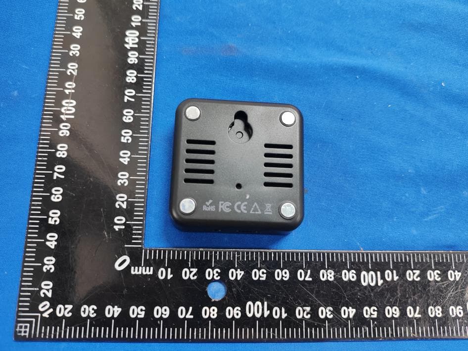
Click to zoom
Application Details
- Equipment Class
- DTS - Digital Transmission System
- Date of Grant
- Feb 06, 2026
- Application Purpose
- Original Equipment
- Equipment Note
- Smart thermometer
- Frequency Range
- 2412.00000000 - 2462.00000000
- Country
- China
Documents & Files
Document Text
Text extracted from the exhibit documents filed with the FCC. Open a document above to read the original.
Users Manual
Smart Thermometer User Manual Model: MC82 1. Before Use – Read First • This device works with the Smart Lif e app for remote alerts, on/off control, and custom sensor settings. • Supports 2.4 GHz Wi-Fi only (not compatible with 5 GHz). Works with iOS/Android. • Place the sensor where the Wi-Fi signal is strong to avoid disconnections or failed uploads. • If your router uses a combined 2.4G/5G network, temporarily split the bands to complete pairing. • Strict router settings (firewall, AP isolation, etc.) may block connection. Adjust if needed or consult your router provider. • If your router has reached its device limit, disconnect another device or use a dif ferent router. Suction Mount ×1 Type-C Power Cable ×1 Thermometer Unit ×1 User Manual ×1 2.What’s in the Box 1.5m Temperature Sensor Cable ×1 Smart Thermometer User Manual Model: MC82 3. Hardware Overview Button Long press (2s): Enter pairing mode Short press: Turn backlight ON/OFF Button Long press (2s): Switch temperature unit (/) Short press: Turn sound ON/OFF Indicator Lights Blue Light (blinking):Device is in pairing mode Red Light (blinking): Temperature abnormal / outside the set range Green Light (solid): Temperature is within the normal range 4. Set UP 4.1 Power On Your Device 4.2 Choose Your Usage Mode Connect the sensor to a 5V/1A (or higher) USB power adapter. Note:The power adapter is not included. Use Without Network (Offline Mode) If you prefer not to connect the device to the internet or use the app, the thermometer can still function normally in offline mode. Note: In offline mode, the sensor cannot perform remote monitoring or send online alerts. Use With Network (Recommended) Download the “Smart Life” app via Google Play, Apple App Store, or by scanning the QR code below. and register a user on the application. Google PlayApp Store Smart Life 4.3 Add the Device Turn on your Wi-Fi (2.4 GHz) and Bluetooth on your phone. In the Smart Life app, tap “+”button → "Add Device” on the upper right. Long press the button on the device for 2 seconds to enter pairing mode. ④ The blue indicator light blinks, indicating that the device is ready to pair. Note: • When powered on for the first time, the device automatically enters pairing mode for 3 minutes. • For manual pairing afterward, Long press the button for 2 seconds. The device will stay in pairing mode for 1 minute, indicated by the blinking blue light. After selecting your Wi-Fi network, enter the password and tap "Next". After the device connects, tap "Done". 5. Installation Position the device in close proximity to your Wi-Fi router and at an elevated location within the same space, avoiding major physical barriers and electronic interference sources for optimal performance. Note: Clean & dry frost/moisture/debris from the specific suction cup mounting spot in the fridge. Residue breaks the seal, causing unstable placement—ensure a tight fit for accuracy. 6. Smart Life App Interface Overview 6.1 Home Page Temperature Display Use the Hour, Day, Week, Month, Year buttons to change the time range displayed on the temperature graph. You can also download up to one year of historical temperature data. Data Refresh Temperature calibration is available under this section. Under normal use, recalibration is not required throughout the entire sensor lifecycle. Accuracy tolerance: ±0.9°F / ±0.5°C Settings Button Tap this icon to open the sensor settings page, where you can adjust alarms, units, notifications, and more. The sensor will automatically switch to the temperature unit you set on your mobile phone. °F /°C Swich This section shows the current temperature reading. You can switch between °F /°C using the toggle on the right side. Time Chart 6.2 Sensor Settings When this feature is enabled, you can set a normal temperature range. If the sensor’s temperature rises above the maximum value or drops below the minimum value, an alarm will be triggered. This anti-false-alarm feature prevents unnecessary freezer alerts by notifying you 1–10 minutes after the temperature exceeds the set range—helping avoid false alarms when opening the refrigerator door briefly. Set how long the device will sound an alarm, adjustable from 1-10 minutes. If the temperature remains abnormal, you can set a repeat interval of 1–12 hours to ensure you don’t miss important alerts. Enable or disable app notifications for temperature alerts. Turn the device’s audible alarm ON or OFF. Tap Alarm Log to view the sensor’s history of alert notifications. Temp Alerting Delayed Alarm Alarm Duration Alarm Interval Alarm Notification Alarm Sound Alarm Log 6.3 Official Settings Page Here you can access additional features, including: Link the sensor with other smart devices Allow friends or family to monitor the sensor together. Note: Phone call and SMS notifications are paid premium services provided by the Smart Life app. Please evaluate your needs carefully before subscribing. Custom Sensor Name Tap-to-Run and Automation Share Device Message Notification Setting Check Device Network Offline Notification 7. Product Parameter Model Dimensions Weight Power Supply Wireless Connectivity Temperature Detection Range Temperature Accuracy Temperature Refresh Rate Sensor Cable Length MC82 2.28 × 2.28 × 0.71 inches (58 × 58 × 18 mm) 1.76 oz (50 g) 5V/1A USB power adapter (not included) 2.4 GHz Wi-Fi -40°F to 158°F (-40 to 70) ±0.9°F / ±0.5°C Every 2 seconds 1.5 m 8. Troubleshooting Q:When does the temperature become accurate? What is the accuracy? A: After the sensor is powered on, it may take 15–20 minutes for the temperature reading to stabilize and reflect the actual environment. The accuracy is ±0.9°F / ±0.5°C. Q: What should I do if the device cannot connect to Wi-Fi? A: This sensor supports 2.4 GHz Wi-Fi only. Ensure the sensor is within the Wi-Fi coverage area. The recommended distance is within 10–15 meters from the router. Reduce potential signal obstacles such as metal doors, multiple walls, or thick walls, which …
Text truncated - open the document above for the full version.
Attestation Statements
Dongguan Jinghe Electronic Technology Co., Ltd Covered Equipment Certification Attestation Letter 1/31/2026 Federal Communications Commission Authorization and Evaluation Division 7435 Oakland Mills Road Columbia, MD 21046 USA ATTN.: Reviewing Engineer FCC ID: 2BECQ-MC82 Dongguan Jinghe Electronic Technology Co., Ltd (“the applicant”) certifies that the equipment for which authorization is sought is not “covered” equipment prohibited from receiving an equipment authorization pursuant to section 2.903 of the FCC rules. Note: If the equipment for which the applicant seeks authorization is produced by any of the entities identified on the current Covered List, the applicant should include an explanation on why the equipment is not “covered” equipment. Dongguan Jinghe Electronic Technology Co., Ltd (“the applicant”) certifies that, as of the date of the filing of the application, the applicant is not identified on the Covered List (as a specifically named entity or any of its subsidiaries or affiliates) as an entity producing “covered” equipment. Dongguan Jinghe Electronic Technology Co., Ltd (“the applicant”) certifies that the equipment for which authorization is sought does not include cybersecurity or anti-virus software produced or provided by Kaspersky Lab, Inc. or any of its successors and assignees, including equipment with integrated Kaspersky Lab, Inc. (or any of its successors and assignees) cybersecurity or anti-virus software pursuant to DA-24-886 and KDB 986446 D01 Covered Equipment Guidance section B(2a). <Signature>: Name: Davy wu Title: Manager Company: Dongguan Jinghe Electronic Technology Co., Ltd Date: 1/31/2026
Attestation Statements
Dongguan Jinghe Electronic Technology Co., Ltd * the applicant must designate a contact located in the United States for purposes of acting as the applicant’s agent for service of process, regardless of whether the applicant is a domestic or foreign entity. An applicant located in the United States may designate itself as the agent for service of process. U.S. Agent Designation for Service of Process - Certification Attestation Letter 1/31/2026 TO: Federal Communications Commission 7435 Oakland Mills Road Columbia, MD 21046 ATTN.: Reviewing Engineer FCC ID: 2BECQ-MC82 FRN of applicant: 0034687590 Per section 2.911(d)(7) of the FCC rules, [Dongguan Jinghe Electronic Technology Co., Ltd] (“the applicant”) certifies that the equipment for which authorization is sought is designated to the following U.S. agent* for service of process: Company Name: Herland International Trading Inc FCC Registration Number (FRN): 0036324101 Physical U.S. Company Address: 1370 Valley Vista Dr Ste 200 Diamond Bar, CA 91765 Contact Person: Jianfeng Gao Agent Email Address: [email protected] The above contact person accepts the obligation for service of process. The applicant accepts to maintain an agent for no less than one year after the grantee has terminated all marketing and importation or the conclusion of any Commission-related proceeding involving the equipment. Applicant Signed: Signed: Printed name: Davy wu Title: Manager Company Name: Dongguan Jinghe Electronic Technology Co., Ltd Date: 1/31/2026 Agent Signed (if different from Applicant): Signed: Printed name: Jianfeng Gao Title: Manager Company Name: Herland International Trading Inc Date: 1/31/2026
Cover Letter(s)
Dongguan Jinghe Electronic Technology Co., Ltd 2026-01-31 Federal Communications Commission Authorization & Evaluation Division 7345 Oakland Mills Road Columbia, Maryland 21046 Authority to Act as Agent On our behalf, I appoint Shenzhen DL Testing Technology Co., Ltd.(101-201, Comprehensive Building, Tongzhou Electronics Longgang Factory Area, No.1 Baolong Fifth Road, Baolong Community, Baolong Street, Longgang District, Shenzhen, China)to act as our agent in the preparation of this application for equipment certification. I certify that submitted documents properly describe the device or system for which equipment certification is sought. I also certify that each unit manufactured, imported or marketed, as defined in the Federal Communications Commission’s regulations will have affixed to it a label identical to that submitted for approval with this application. For instances where our authorized agent signs the application for certification on our behalf, I acknowledge that all responsibility for complying with the terms and conditions for certification, still resides with Dongguan Jinghe Electronic Technology Co., Ltd(Room 301, No. 3, Hongshan 1st Street, Xin'an Community, Chang'an Town, Dongguan City, China) <Signature>: Name: Davy wu Title: Manager Company: Dongguan Jinghe Electronic Technology Co., Ltd
Cover Letter(s)
Dongguan Jinghe Electronic Technology Co., Ltd 2026-01-31 Federal Communications Commission Authorization & Evaluation Division 7345 Oakland Mills Road Columbia, Maryland 21046 RE: LETTER OF AGENT AUTHORIZATION To Whom It May Concern: We, the undersigned, hereby authorize Compliance Testing, LLC to act on our behalf in all matters relating to application for equipment authorization, including the signing of all documents relating to these matters. We also hereby certify that no party to the application authorized hereunder is subject to the denial of benefits, including FCC benefits, pursuant to Section 5301 of the Anti-Drug Abuse Act of 1988, 21 U.S.C.853(a). Sincerely, <Signature>: Name: Davy wu Title: Manager Company: Dongguan Jinghe Electronic Technology Co., Ltd
Cover Letter(s)
Dongguan Jinghe Electronic Technology Co., Ltd 2026-01-31 Equipment Autorisation Division Federal Communications Commission 7435 Oakland Mills Road Columbia, MD 21046 FCC ID: 2BECQ-MC82 Product Name: Smart thermometer Request for Confidentiality Pursuant to Sections 0.457 and 0.459 of the commission’s rules, we hereby request that the following documents be held confidential: (List here the documents for which you are seeking confidentiality – for example ...) Schematics Block diagram Operation description These materials contain trade secrets and proprietary information and are not customarily released to the public. The public disclosure of this information might be harmful to the company and provide unjustified benefits to our competitors. <Signature>: Name: Davy wu Title: Manager Company: Dongguan Jinghe Electronic Technology Co., Ltd
External Photos
Shenzhen DL Testing Technology Co., Ltd. EUT PHOTO(External Photos) Shenzhen DL Testing Technology Co., Ltd. Shenzhen DL Testing Technology Co., Ltd. Shenzhen DL Testing Technology Co., Ltd. ※※※※※ END OF REPORT ※※※※※
ID Label/Location Info
Size: 22*18mm Model.: MC82 FCC ID: 2BECQ-MC82 Label location
Internal Photos
Shenzhen DL Testing Technology Co., Ltd. EUT PHOTO(Internal Photos) ANT Shenzhen DL Testing Technology Co., Ltd. Shenzhen DL Testing Technology Co., Ltd. ※※※※※ END OF REPORT ※※※※※
RF Exposure Info
FCC ID: 2BECQ-MC82 RF Exposure Evaluation Limits The criteria listed in the following table shall be used to evaluate the environment impact of human exposure to radio frequency (RF) radiation as specified in KDB 447498 D01 V06 and 1.1307(b) Limits for Maximum Permissible Exposure (MPE) Frequency range (MHz) Electric field strength (V/m) Magnetic field strength (A/m) Power density (mW/cm 2 ) Averaging time (minutes) (A) Limits for Occupational/Controlled Exposures 0.3–3.0 614 1.63 *(100) 6 3.0–30 1842/f 4.89/f *(900/f 2 ) 6 30–300 61.4 0.163 1.0 6 300–1500 f/300 6 1500–100,000 5 6 (B) Limits for General Population/Uncontrolled Exposure 0.3–1.34 614 1.63 *(100) 30 1.34–30 824/f 2.19/f *(180/f 2 ) 30 30–300 27.5 0.073 0.2 30 300–1500 f/1500 30 1500–100,000 1.0 30 f = frequency in MHz Friis transmission formula: Pd = (Pout*G)/(4*pi*r 2 ) Where Pd = power density in mW/cm 2 , Pout = output power to antenna in mW; G = gain of antenna in linear scale, Pi = 3.1416; R = distance between observation point and center of the radiator in cm Pd id the limit of MPE, 1 mW/cm 2 . If we know the maximum gain of the antenna and the total power input to the antenna, through the calculation, we will know the distance r where the MPE limit is reached. Test Procedure Software provided by client enabled the EUT to transmit and receive data at lowest, middle and highest channel individually. EIRP=EMeas+20log(dMeas)-104.7 EIRP is the equivalent isotropically radiated power, in dBm EMeas is the field strength of the emission at the measurement distance, in dBμV/m dMeas is the measurement distance, in m Test Result of RF Exposure Evaluation wifi 2.4G mode Channel Output power to antenna (dBm) Output power to antenna (mW) Power Density at R=20cm (mW/cm 2 ) Limit (mW/cm 2 ) Result 802.11b 15.56 35.9749 0.0128 1.0 PASS 802.11g 16.44 44.0555 0.0157 1.0 PASS 802.11n HT20 15.98 39.6278 0.0141 1.0 PASS 802.11n HT40 16.03 40.0867 0.0143 1.0 PASS Remark: antenna gain=2.54dBi
Test Report
Shenzhen DL Testing Technology Co., Ltd. Report No.: DLE-260126034R Test Report Tel: 400-688-3552 Web:www.dl-cert.com Email: [email protected] Page 1 of 48 FCC Part 15C Test Report FCC ID: 2BECQ-MC82 Applicant: Dongguan Jinghe Electronic Technology Co., Ltd Address: Room 301, No. 3, Hongshan 1st Street, Xin'an Community, Chang'an Town, Dongguan City, China Manufacturer: Dongguan Jinghe Electronic Technology Co., Ltd Address: Room 301, No. 3, Hongshan 1st Street, Xin'an Community, Chang'an Town, Dongguan City, China Product Name: Smart thermometer Trade Mark: N/A Model Number: MC82 Date of Receipt: Jan. 26, 2026 Test Date: Jan. 26, 2026 - Feb. 04, 2026 Date of Report: Feb. 04, 2026 Prepared By: Shenzhen DL Testing Technology Co., Ltd. Address: 101-201, Comprehensive Building, Tongzhou Electronics Longgang Factory Area, No.1 Baolong Fifth Road, Baolong Community, Baolong Street, Longgang District, Shenzhen, China Applicable Standards: FCC PART 15 C 15.247 ANSI C63.10:2020 Test Result: Pass Report Number: DLE-260126034R Prepared (Test Engineer): Alisa Song Reviewer (Supervisor): Jack Bu Approved (Manager): Jade Yang This test report is based on a single evaluation of one sample of above mentioned products. It is not permitted to be duplicated in extracts without written approval of Shenzhen DL Testing Technology Co., Ltd. Shenzhen DL Testing Technology Co., Ltd. Report No.: DLE-260126034R Test Report Tel: 400-688-3552 Web:www.dl-cert.com Email: [email protected] Page 2 of 48 Table of Contents Page 1 . SUMMARY OF TEST RESULTS 4 1.1 MEASUREMENT UNCERTAINTY 4 2 . GENERAL INFORMATION 5 2.1 GENERAL DESCRIPTION OF EUT 5 2.2 DESCRIPTION OF TEST MODES 6 2.3 BLOCK DIGRAM SHOWING THE CONFIGURATION OF SYSTEM TESTED 6 2.4 DESCRIPTION OF SUPPORT UNITS(CONDUCTED MODE) 7 2.5 TABLE OF PARAMETERS OF TEST SOFTWARE SETTING 7 2.6 EQUIPMENTS LIST FOR ALL TEST ITEMS 8 3 . EMC EMISSION TEST 9 3.1 CONDUCTED EMISSION MEASUREMENT 9 3.1.1 POWER LINE CONDUCTED EMISSION LIMITS 9 3.1.2 TEST PROCEDURE 9 3.1.3 DEVIATION FROM TEST STANDARD 9 3.1.4 TEST SETUP 10 3.1.5 EUT OPERATING CONDITIONS 10 3.1.6 TEST RESULTS 10 3.2 RADIATED EMISSION MEASUREMENT 13 3.2.1 RADIATED EMISSION LIMITS 13 3.2.2 TEST PROCEDURE 14 3.2.3 DEVIATION FROM TEST STANDARD 14 3.2.4 TEST SETUP 14 3.2.5 EUT OPERATING CONDITIONS 15 3.2.6 TEST RESULTS (BETWEEN 9KHZ – 30 MHZ) 16 3.2.7 TEST RESULTS (BETWEEN 30MHZ – 1GHZ) 17 3.2.8 TEST RESULTS (1GHZ~25GHZ) 19 3.3 RADIATED BAND EMISSION MEASUREMENT 23 3.3.1 TEST REQUIREMENT: 23 3.3.2 TEST PROCEDURE 23 3.3.3 DEVIATION FROM TEST STANDARD 23 3.3.4 TEST SETUP 24 3.3.5 EUT OPERATING CONDITIONS 24 3.4 CONDUCTED BAND EDGE EMISSION&CONDUCTED SPURIOUS EMISSIONS MEASUREMENT 29 3.4.1 APPLICABLE STANDARD 29 3.4.2 TEST PROCEDURE 29 3.4.3 DEVIATION FROM STANDARD 29 Shenzhen DL Testing Technology Co., Ltd. Report No.: DLE-260126034R Test Report Tel: 400-688-3552 Web:www.dl-cert.com Email: [email protected] Page 3 of 48 Table of Contents Page 3.4.4 TEST SETUP 29 3.4.5 EUT OPERATION CONDITIONS 29 3.4.6 TEST RESULTS 29 4 . AVERAGE OUTPUT POWER 34 4.1 APPLIED PROCEDURES / LIMIT 34 4.1.1 TEST PROCEDURE 34 4.1.2 DEVIATION FROM STANDARD 34 4.1.3 TEST SETUP 34 4.1.4 EUT OPERATION CONDITIONS 34 4.1.5 TEST RESULTS 35 5 . POWER SPECTRAL DENSITY TEST 38 5.1 APPLIED PROCEDURES / LIMIT 38 5.1.1 TEST PROCEDURE 38 5.1.2 DEVIATION FROM STANDARD 38 5.1.3 TEST SETUP 38 5.1.4 EUT OPERATION CONDITIONS 38 5.1.5 TEST RESULTS 39 6 . 6DB BANDWIDTH TEST 42 6.1 APPLIED PROCEDURES / LIMIT 42 6.1.1 TEST PROCEDURE 42 6.1.2 DEVIATION FROM STANDARD 42 6.1.3 TEST SETUP 42 6.1.4 EUT OPERATION CONDITIONS 42 6.1.5 TEST RESULTS 43 7 . ANTENNA REQUIREMENT 48 7.1 STANDARD REQUIREMENT 48 7.2 EUT ANTENNA 48 8 . TEST SEUUP PHOTO 48 9 . EUT PHOTO 48 Shenzhen DL Testing Technology Co., Ltd. Report No.: DLE-260126034R Test Report Tel: 400-688-3552 Web:www.dl-cert.com Email: [email protected] Page 4 of 48 1.. SUMMARY OF TEST RESULTS Test procedures according to the technical standards: FCC Part15 (15.247) , Subpart C Standard Section Test Item Judgment Remark 15.207 Conducted Emission PASS 15.205, 15.209, 15.247(d) Radiated Spurious Emission PASS 15.209, 15.205 Band Edge Emission PASS 15.247(d) Conducted Spurious Emissions PASS 15.247(b) Average Output Power PASS 15.247(a)(2) 6dB Bandwidth PASS 15.247(e) Power Spectral Density PASS 15.203 Antenna Requirement PASS NOTE: (1)” N/A” denotes test is not applicable in this Test Report Test lab: Shenzhen DL Testing Technology Co., Ltd. Address: 101-201, Comprehensive Building, Tongzhou Electronics Longgang Factory Area, No.1 Baolong Fifth Road, Baolong Community, Baolong Street, Longgang District, Shenzhen, China FCC Test Firm Registration Number: 854456 Designation Number: CN1307 IC Registered No.: 27485 CAB ID.: CN0118 1.1. MEASUREMENT UNCERTAINTY The reported uncertainty of measurement y ± U, where expended uncertainty U is based on a standard uncertainty multiplied by a coverage factor of k=2,providing a level of confidence of approximately 95 %。 No. Item Uncertainty 1 Conducted Emission Test ±2.56dB 2 RF power,conducted ±0.42dB 3 Spurious emissions,conducted ±2.76dB 4 All emissions,radiated(<1G) ±3.65dB 5 All emissions,radiated(>1G) ±4.89dB 6 Temperature ±0.5°C 7 Humidity ±2% 8 6dB Bandwidth ±0.2% 9 Power Spectral Density ±2.45dBm Shenzhen DL Testing Technology Co., Ltd. Report No.: DLE-260126034R Test Report Tel: 400-688-3552 Web:www.dl-cert.com Email: [email protected] Page 5 of 48 2.. GENERAL INFORMATION 2.1. GENERAL DESCRIPTION OF EUT Product Name: Smart thermometer Trade Mark: N/A Model Number: MC82 Test Model: MC82 Model Difference N/A Operation Frequency: 2412~2462 MHz for 802.11b/g/nHT20 2422~2452 MHz for 802.11nHT40 Channel numbers: 11 Channels for 802.11b/g/n(HT20) 7 channels for 802.11nHT40 Channel separation: 5MHz Modulation technology: 802.11b: DSSS (CCK, DQPSK, DBPSK) 802.11g/n(20/40): OFDM(QPSK, BPSK, 16-QAM, 64-QAM) Rate of Transmitter 802.11b: 11/5.5/2/1Mbps 802.11g: 54/48/36/24/18/12/9/6Mbps 80…
Text truncated - open the document above for the full version.
Test Report
AntennaSpecification Manufacture:TUYA ProductName:WBR3Antenna AntennaType:PCB TestDate:2019.05.20 Testedby:LongWang Approvedby:Licco Content 1.GeneralDescription.................................................................................1 2.TestConfigurations...................................................................................2 2.1TestEnvironment............................................................................2 2.2TestEquipment...............................................................................2 2.3TestPrinciple...................................................................................2 3.TestResults..............................................................................................3 3.1GainandEfficiency..........................................................................3 3.2RadiationPattern............................................................................4 4.AntennaDimensions................................................................................6 5.EUTPhoto................................................................................................6 6.TestSetupPhoto......................................................................................7 1 1.GeneralDescription ManufacturerHangzhouTuyaInformationTechnologyCo.,Ltd Address Room701,Building3,MoreCenter,No.87GuDunRoad, Hangzhou,Zhejiang,China TestLocation Room106,Building3,LetongSciencePark,No.500, QiuyiRoad,BinjiangDistrict,Hangzhou ProductNameWBR3Antenna Productmodel WBR3 AntennaType PCBAntenna TestItems Gain;Efficiency;RadiationPattern TestFrequency 2400-2500MHz TestStandard ANSI/IEEEStd149-1979 2 2.TestConfigurations 2.1TestEnvironment Temperature(°C)25 Humidity(%RH)60 AtmosphericPressure(kPa)100.5 2.2TestEquipment TestSystemTEM24Multi-probeMicrowaveChamber TestInstrumentAgilentE5071B 2.3TestPrinciple 3 3.TestResults 3.1GainandEfficiency Frequency(MHz)PeakGain(dBi)Efficiency(%) 2400 1.6252.29 2410 1.7152.17 2420 1.9353.14 2430 1.9854.16 2440 2.0057.62 2450 2.1759.64 2460 2.4561.55 2470 2.3860.64 2480 2.5462.86 2490 2.3059.85 2500 2.4960.41 4 3.2RadiationPattern Phi02D Phi902D 5 Theta902D 2480MHz3D 6 4.AntennaDimensions 5.EUTPhoto 7 6.TestSetupPhoto
Test Setup Photos
Shenzhen DL Testing Technology Co., Ltd. EUT TEST PHOTO Radiated Measurement Photos Shenzhen DL Testing Technology Co., Ltd. Conducted Measurement Photos ※※※※※ END OF REPORT ※※※※※
Contact Information
Applicant
Davy wu
[email protected]Fax: 18374731994
Technical Contact
Herland International Trading IncJianfeng Gao
1370 Valley Vista Dr Ste 200 Diamond Bar, CA 91765 · Diamond Bar, California · United States
Test Firm
Shenzhen DL Testing Technology Co., Ltd.Jade Yang
Technical Specifications
| # | Rule Parts | Frequency Range | Power Output |
|---|---|---|---|
| 1 | 15C | 2.41 GHz - 2.46 GHz | 44.10 mW |