FCCID.CO- FCC ID Database
HomeCompaniesEquipment ClassesSearch

© 2026 FCC ID Database. All rights reserved.

AboutContactData sourced from FCC public records
  1. Home/
  2. Shenzhen concentric technology Co., LTD/
  3. 2BEH9-TX01

2BEH9-TX012.4GWiFi audio and video

Shenzhen concentric technology Co., LTD
2.4GWiFi audio and video - FCC ID 2BEH9-TX01 - Shenzhen concentric technology Co., LTD
Click to zoom

Application Details

Equipment Class
DTS - Digital Transmission System
Date of Grant
Jan 11, 2024
Application Purpose
Original Equipment
Date of Application
Jan 11, 2024
Equipment Note
2.4GWiFi audio and video
Frequency Range
2412.00000000 - 2462.00000000
Company
Shenzhen concentric technology Co., LTD
Country
China

Documents & Files

Select a file to view

Users Manual

↗

Attestation Statements

↗
↗
↗

Cover Letter(s)

↗
↗
↗

External Photos

↗

ID Label/Location Info

↗

Internal Photos

↗

RF Exposure Info

↗

Test Report

↗
↗
↗

Test Setup Photos

↗

Document Text

Text extracted from the exhibit documents filed with the FCC. Open a document above to read the original.

Users Manual

W‐CAR WiFi driving record/reversing visual camera manual IOS download Android Download 1.Product introduction............................................. 2.Main functions...................................................... 3.Download application............................................. 4.Tips for use......................................................... 5.Product installation............................................. 6.Troubleshooting................................................... 1. Product introduction W‐CAR is the best intelligent vehicle safety product. It can be installed in the front, rear, left and right of the vehicle blind area to realize safe driving.Widely used in cars, trucks, RV, trailers, buses, trucks, engineering vehicles and other vehicles ● intelligent vision realization with simple installation and low cost; ● H.264 chip imported from the United States, with clear and smooth image ● high power WiFi module with strong signal and long transmission distance. 2 main functions ●intelligent video recording function Video recording and video sharing can be realized by connecting the intelligent device to the WiFi of the camera ● functions of intelligent electronic rearview mirror Real time viewing is carried out through the device end. After inputting the rear view video, real-time viewing can be carried out.Look at the reasons behind the vehicle and look at it as a whole ● intelligent forward-looking function It can be installed in the front, rear, left and right visual blind areas, and the software can be opened to switch each camera and monitor in real time. 3 download application: ● scan and download the QR code, open the scanning window, and then scan the QR code of the product manual ● search and download Apple device enters app srore search: W-CAR download; Android devices enter Google / APP treasure or Huawei application market search: W‐CAR Download 4. Use skills ● terminal interface Icon RECORD SCREENSHOT PLAYER MIRROR WIFI SET UP 1. Record: video recording function. Click this button to record real‐time video signals and save them in the intelligent device; 2, screenshot: photographing function. Click this button to intercept the current picture and save it in the smart device; 3Player: play function. Click this button to enter the video and picture folder. You can select videos to play and browse pictures, and save important videos and pictures in the picture library of intelligent devices after selection. 4Mirror: mirror function. Click this button to switch the front and rear view of the image and store it, so that your camera can be installed in the front or rear view without worry; 5, WiFi: WiFi direct connection signal indication. When there is no WiFi signal connection, the signal is red. When WiFi is connected, the signal is green.When the first connection is successful, the list of connected cameras will be stored here. In the future, you can directly connect to the camera by clicking this list.If there are four front, rear, left and right cameras installed, click this WiFi sign after connection to display the list of four cameras. When the signal of which camera needs to be displayed, directly click the SSID of the camera to connect directly; 6, set-up: setting function. Click this button to enter the setting menu, which can turn on or off the display of reversing logo and the switching of general clear / HD video; ● use the Android device, open the mobile phone settings, find the WiFi of W-CAR... SSID in the wireless LAN and connect. The password is required for the first time: 12345678, which is no longer required. After connecting, open the W-CAR app, and the video will pop up automatically.When 4G network is required, click exit, and the connection between W-CAR...... and the software background will be automatically disconnected. (for products specially used for rear-view reversing, it is necessary to engage reverse gear to trigger start and reverse gear to exit. It is also necessary to set in mobile phone or vehicle navigation products to allow W-CAR suspension window permission or background operation permission. Turn on battery management, apply power consumption management, and turn on the allow full background behavior switch of the wcar.) ● usage of IOS system 1Automatic connection: find the W-CAR...... name WiFi and click direct automatic connection (password required for the first connection: 12345678 password is no longer required after successful connection) 2.Manual connection: remember in the IPv4 address bar: IP address, subnet mask, router, these three lines of numbers. 3.Click Configure IP, select Manual, and fill in the following three lines of numbers at the bottom to save 5.Product installation (very important, please read carefully) 1.First, turn off the onboard power.Do not turn on the power when the camera power cord is not properly connected 2.Determine the camera type and select the installation location method Installation method of rear view products: Method 1: the red power line is connected to the 12V + positive position of ACC power supply of fuse box, the black power line is connected to the negative GND harness of fuse box, and the yellow line is connected to the power + pole of reversing lamp. Start the vehicle;The yellow line is the reverse trigger line. When WiFi is connected, open the app and let it exit to the background. When it is in reverse gear, the reverse video will be displayed immediately, and when it is out of gear, the video will be exited; Method 2: connect the power cord, (red 12V positive pole, black negative pole) and insert the cigarette lighter. Press the switch to use it; Side view product installation method; Method 1: connect the power cord, adjust the camera angle, insert the cigarette lighter, and then press the switch Method 2: cut the wires at the switch position of the cigarette lighter, red and black wires.The red power cord is connected to the ACC power supply 12V + positiv…

Text truncated - open the document above for the full version.

Attestation Statements

Section Company n Address: 4 Product N a FCCID: 2B Model(s): T TX14, TX15 TX29, TX30 2.911(d)(5 ) We, [Shen z authorizatio  Pro  Ide n Yours sinc e Name: Du X Title: Mana Company n Signature: NOTE 1 “Covered List https://www.f c References; 1) 986446 D 0 https://apps.fc 2) Federal R e https://www.fe munications-s Sh 2.911(d) name: Shen / F, Building ame: 2.4GW EH9-TX01 TX01, TX02 5, TX16, TX 0 )(i) Equipm zhen conce on is sough hibited fro m ntified as an erely, Xiaoyan ge name: She ”; is the List o cc.gov/supplyc 01 Covered Eq cc.gov/oetcf/kd egister docume ederalregister. supply-chain-t henzhen )(5)(i) Ce nzhen conce g A5, Fuwe WiFi audio a , TX03, TX 0 X17, TX18, mentType ntric techn o t through ce m receiving n equipmen enzhen conc of Equipment a chain/covered quipment v01 db/forms/FTS ent 2022-2826 gov/documen hrough-the n concen ertificatio entric techn i Second In nd video 04, TX05, T TX19, TX20 ology Co., L ertification i an equipm e nt type in the centric tech and Services C list SearchResul t 63 published o nts/2023/02/06 ntric tec on – Equi nology Co., ndustrial Zon TX06, TX07 0, TX21, TX LTD] (“the a s not: ent authoriz e “Covered Da t hnology Co. Covered By S tPage.cfm?sw on 02/06/23 6/2022-28263/ chnology 2. ipmentTy LTD ne, Fuyong , TX08, TX 0 X22, TX23, T pplicant”) c zation pursu List” NOTE 1 te: Jan. 11, , LTD ection 2 of Th witch=P&id=32 /protecting-ag y Co., LT 911 (d)(5)(i) Eq ype , Baoan Dis 09, TX10, T TX24, TX25 ertify that th uant to § 2.9 2024 e Secure Netw 5672 ainst-national- TD quipment Type A strict, Shenz TX11, TX12, 5, TX26, TX he equipme 903; of the F works Act, ava -security-threa Attestation v1.2 zhen, China , TX13, X27, TX28, ent for which FCC rules. ailable at ats-to-the-com 2 a h m

Attestation Statements

Section Company n Address: 4 Product N a FCCID: 2BE Model(s): T TX14, TX15 TX29, TX30 2.911(d)(5 ) We, [Shenz filing of the pursuant t o Yours sinc e Name: Du X Title: Mana Company n Signature: NOTE 1 Delete option NOTE 2 “Covered List https://www.f c References; 1) 986446 D 0 https://apps.fc 2) Federal R e https://www.fe munications-s Sh 2.911(d) name: Shen / F, Building ame: 2.4GW EH9-TX01 TX01, TX02 5, TX16, TX 0 )(ii) Applica zhen conce applicatio n o §1.50002 erely, Xiaoyan ge name: She not applicable ”; is the List o cc.gov/supplyc 01 Covered Eq cc.gov/oetcf/kd egister docume ederalregister. supply-chain-t henzhen )(5)(ii) Ce nzhen conce g A5, Fuwe WiFi audio a , TX03, TX 0 X17, TX18, ant filing ntric techn o n, the applic of this chap enzhen conc e to this applic of Equipment a chain/covered quipment v01 db/forms/FTS ent 2022-2826 gov/documen hrough-the n concen ertificatio entric techn i Second In nd video 04, TX05, T TX19, TX20 ology Co., L cant is is no pter,as an e centric tech cation. and Services C list SearchResul t 63 published o nts/2023/02/06 ntric tec on – App nology Co., ndustrial Zon TX06, TX07 0, TX21, TX LTD] (“the a ot identified ntity produc Dat hnology Co. Covered By S tPage.cfm?sw on 02/06/23 6/2022-28263/ chnology plicant (C LTD ne, Fuyong , TX08, TX 0 X22, TX23, T pplicant”) c d NOTE 1 on th cing covere te: Jan. 11, , LTD ection 2 of Th witch=P&id=32 /protecting-ag y Co., LT 2.911 (d)(5 Covered L , Baoan Dis 09, TX10, T TX24, TX25 ertify that, a e “Covered dcommuni c 2024 e Secure Netw 5672 ainst-national - TD 5)(ii) Applicant A List ) strict, Shenz TX11, TX12, 5, TX26, TX as of the da d List” NOTE 2 ,e cations equ works Act, ava -security-threa Attestation v1.3 zhen, China , TX13, X27, TX28, ate of the established ipment. ailable at ats-to-the-com 3 a d m

Cover Letter(s)

Co m Ad d She Pr o Mo d TX1 TX2 Pr o We act We an d issu our Sig Na m Title Com S mpany: Sh dress: 4 / F enzhen, Ch oduct Name del Numbe 12, TX13, T 26, TX27, T oduct Desc authorize M on our beha declare tha d certificatio ues concern behalf shal nature: me: e: mpany: Shenzh enzhen co F, Building hina e: 2.4GWiF er(s): TX01, X14, TX15, X28, TX29, ription: 2.4 MiCOM Lab alf on all ma at MiCOM L n of equipm ning the app ll have the s Du Xiaoya Manage Shenzhen hen conc Agen ncentric te A5, Fuwei i audio an d , TX02, TX0 , TX16, TX1 , TX30 4GWiFi aud bs Inc., 575 atters conce Labs Inc. is ment to the r proval applic same effect an n concentri centric nt Auth echnology Second In d video 03, TX04, T 17, TX18, T dio and vid Boulder C o erning the c allowed to f regulatory a cation. Any t as acts of ic technolo technol horizat Co., LTD dustrial Z o TX05, TX06, TX19, TX20, eo ourt, Pleasa certification forward all i agencies as and all acts our own. ogy Co., LT logy Co tion one, Fuyon , TX07, TX0 , TX21, TX2 anton, Califo of above na information s required a s carried ou Date: TD o., LTD ng, Baoan D 08, TX09, T 22, TX23, T ornia 94566 amed equip related to t nd to discu ut by MiCOM Jan. 11, 20 District, TX10, TX11, TX24, TX25 6, USA, to pment. the approva ss any M Labs on 024 , , al

Cover Letter(s)

Office o Federa 7435 O Columb USA Subjec t FCC ID To Wh o Pursua are req u docume These d propriet might b In addi t in Title busine s authoriz For 4 O For 1 It is ou r corresp docume authoriz Sincer e Signat u Name: Title: M Sh of Engineeri l Communic Oakland Mills bia, MD 210 t; Request f D: 2BEH9-TX om It May C nt to the pro uesting the ents from pu documents tary informa be harmful to Schemat Block Di Parts Lis Operatio Tune-up tional to abo 47 CFR §2 ss sensitive zed devices External Test Set Internal P User Ma 45 days, pu OR 180 days pu r understand pondence du ents and thi zation is iss ely, ure: Du Xiaoya n anage henzhen ing Techno cations Com s Road 046 for Confiden X01 Concern, ovisions of t Commissio ublic disclos contain det ation in ope o our comp tic Diagram agram st onal Descrip Procedure ove mention .803 and th informatio n s, we reque Photos tup Photos Photos anual rsuant to P u ursuantto KD ding that all uring the ce s informatio sued. n n conce logy mmission ntiality the Commis on to withho sure indefin tailed syste ration of th e any and wo m ption ned docume e importatio n remains c st Short Te ublic Notice DB 726920 l measurem ertification re on will be av entric te ssion’s rule old the follow nitely. m and equi e equipmen ould give co ents, in orde on rules in T confidential rm Confide e DA 04-170 0 D01. ment test rep eview proce vailable for echnolo s Title 47 S wing attach pment desc nt. The publ ompetitors a er to comply Title 47 CFR until the act ntiality of th 05. ports, FCC ess cannot public revi e ogy Co., Sections §0. hment(s) as criptions an ic disclosu r an unfair ad y with the m R §2.1204, tual market he following ID label for be granted ew once the LTD Date: Jan. 457 and § 0 confidentia d are consi re of these d vantage in marketing re while ensu ting of newly attachmen mat and as confide n e grant of eq 11, 2024 0.459, we al dered as documents the market . egulations ring that y t(s); ntial quipment .

Cover Letter(s)

To W We, TX 0 TX1 Mo d mod Ple a Sig Na m Title Whom It May Shenzhen c 02, TX03, TX 7, TX18, TX del Difference del named dif ase contact m nature: me: D e: M Shenz Mo y Concern, concentric te X04, TX05, TX X19, TX20, TX e: All model’s fferent. Test me if you hav Du Xiaoyan Manage zhen con odel Di chnology Co X06, TX07, T X21, TX22, T s the functio sample mo d ve any quest ncentric t fferenc o., LTD (2.4G TX08, TX09, TX23, TX24, n, software a del: TX01. tion. technolo ce Dec GWiFi audio a TX10, TX11 TX25, TX26 and electric c ogy Co., claratio and video); M 1, TX12, TX1 6, TX27, TX2 circuit are the Date: LTD on Model Numb 13, TX14, TX 28, TX29, TX e same, only Jan. 11, 20 ber: TX01, X15, TX16, X30 y with produc 024 ct

External Photos

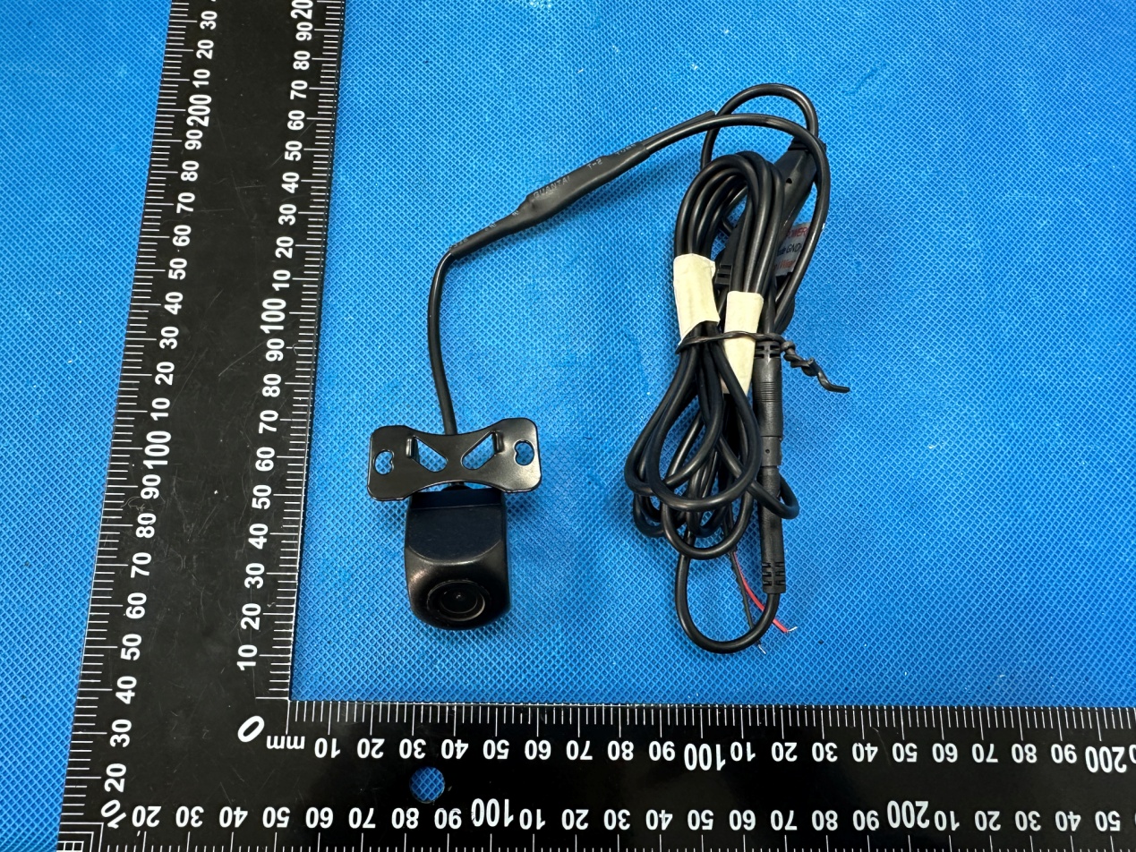
Report No.: HK2401050091-E Page 1 of 5 Annex A External Photos Model and/or type reference: TX01, TX02, TX03, TX04, TX05, TX06, TX07, TX08, TX09, TX10, TX11, TX12, TX13, TX14, TX15, TX16, TX17, TX18, TX19, TX20, TX21, TX22, TX23, TX24, TX25, TX26, TX27, TX28, TX29, TX30 Report No.: HK2401050091-E Page 2 of 5 Antenna Report No.: HK2401050091-E Page 3 of 5 Report No.: HK2401050091-E Page 4 of 5 Report No.: HK2401050091-E Page 5 of 5

ID Label/Location Info

FCC ID LABEL: Ca. 8mm x 10mm label location FCC ID: 2BEH9‐TX01

Internal Photos

Report No.: HK2401050091-E Page 1 of 4 Annex B Internal Photo Model and/or type reference: TX01, TX02, TX03, TX04, TX05, TX06, TX07, TX08, TX09, TX10, TX11, TX12, TX13, TX14, TX15, TX16, TX17, TX18, TX19, TX20, TX21, TX22, TX23, TX24, TX25, TX26, TX27, TX28, TX29, TX30 Report No.: HK2401050091-E Page 2 of 4 Report No.: HK2401050091-E Page 3 of 4 Report No.: HK2401050091-E Page 4 of 4

RF Exposure Info

MPE ESTIMATION FCC ID: 2BEH9-TX01 1, Limit for General Population/ Uncontrolled Exposures Frequency Power density (mW/ cm 2 ) Averaging time(minutes) 300MHz----1.5GHz F/1500 30 1.5GHz---100GHz 1.0 30 2, Estimation Result Max PK Output power(dBm) Tune Up Power(dBm) Max Tune Up power(mW) Antenna Gain(dBi) Antenna Gain (linear) MPE (mW/cm²) 2.4GWIFI 14.82 14±1(15) 31.62 2 1.58 0.00995 Note: Note: The estimation distance is 20cm Note: PK Output power= conducted power. Conducted power see the test report HK2401050091-E When the minimum test separation distance is >20 cm, a distance of 20 cm is applied to determine RF Exposure test exclusion. The test exclusion threshold is 0.00995 mW/cm² which is< 1.0mW/cm², RF Exposure testing is not required. -------The End-------

Test Report

add:东莞市长安镇沙头南区合兴路149号Tel:13724470838Fax:0769-81664308 承认书项目表 ---10 ---9 ---10 ---9 ---8 N/AN/AN/A 7 61增益测试 (Gain Test )6 51S参数测试 (S Parameter )5 41电性测试报告(Test Reports )4 31工程成品图 (Drawing)3 21承认书项目表(Spec Item )2 11承认书封面 (Spec Cover)1 页码 (Page Code) 页数 (Number of Page) 内容 (Contents) NO. GrayCable Color -10 ~ +70 ̊CStorage Temp. -10 ~ +60 ̊COperating Temp. O.D. 1.13mm // 100 mmCable Type TPE / PC / CuAntenna Material Physical Properties 180mmAntenna length 1 WAdmitted Power Linear, VerticalPolarization 3.2 dB / m Max @ 2450 MHzCable Loss 2 dBiGain (Peak) Omni-directionalRadiation -10 dB MaxReturn Loss 1.92 : 1 MaxV.S.W.R 50 0hm Nominal Impedance 2.4GHzFrequency Electrical Properties 电性测试报告 Test Reports S 参数测试 S Parameter Test Agilent E5071C 增益测试 Gain Test Antenna Radiation Pattern VS Gain 0 45 90 135 180 225 270 315 0 0 -10 -10 -20 -20 -30 -30 -40 -40 DESCRIPTION REV APPD DATE .000 ±0.05 GENERAL TOLERANCE DIMENTION .0 .00. ±0.15±0.10±0.20 .0 .00 ANGLES . ±1°±1°±2° T Heat shrink tube Metal pipe

Test Report

Page 1 of 70 Report No.: HK2401050091-E FCC Test Report Test report On Behalf of Shenzhen concentric technology Co., LTD For 2.4GWiFi audio and video Model No.: TX01, TX02, TX03, TX04, TX05, TX06, TX07, TX08, TX09, TX10, TX11, TX12, TX13, TX14, TX15, TX16, TX17, TX18, TX19, TX20, TX21, TX22, TX23, TX24, TX25, TX26, TX27, TX28, TX29, TX30 FCC ID: 2BEH9-TX01 Prepared For : Shenzhen concentric technology Co., LTD 4 / F, Building A5, Fuwei Second Industrial Zone, Fuyong, Baoan District, Shenzhen, China Prepared By : Shenzhen HUAK Testing Technology Co., Ltd. 1-2/F., Building B2, Junfeng Zhongcheng Zhizao Innovation Park, Heping, Fuhai Street, Bao’an District, Shenzhen, Guangdong, China Date of Test: Jan. 05, 2024 ~ Jan. 11, 2024 Date of Report: Jan. 11, 2024 Report Number: HK2401050091-E Applican Address . Manufac t Address . Product d Trade Ma Product n Model an d Standard This publi the Shen source o f and will reproduc e Date of Te Date (s) o Date of Is Te s t R e su t’s name ... .................. turer's Nam .................. description rk: ame ............ d/or type re ds ............... ication may zhen HUA fthe materi not assu m ed material est ............. of performan ssue ............ ult ................ Te s Te c Aut ............... : ............... : me ........... : ............... : n ................. : eference . : ............... : y be reprod K Testing T al. Shenzhe me liability due to its p .................. nce of tests .................. .................. sting Engine chnical Man thorized Sig Test Re Shenzhen 4 / F, Buil d District, Sh Shenzhen 4 / F, Buil d District, Sh N/A 2.4GWiFi a TX01, TX0 TX10, TX1 TX19, TX2 TX28, TX2 FCC Rules ANSI C63. uced in wh Technology en HUAK T for damag placement a ............. : ............. : ............. : ............. : eer : nager : gnatory : Page 2 of sult Cert concentric ding A5, Fuw henzhen, C concentric ding A5, Fuw henzhen, C audio and v 02, TX03, T 11, TX12, TX 20, TX21, T 29, TX30 s and Regu .10: 2013 ole or in p a y Co., Ltd. Testing Tech ges resultin and context. Jan. 05, 202 Jan. 11, 202 Pass f70 tification technology wei Second hina technolog y wei Second hina video X04, TX05 , X13, TX14, X22, TX23 , lations Part art for non-c is acknow hnology Co ng from the 24 ~ Jan. 11 24 (Len Liao (Sliver Wa (Jason Zh o Report n y Co., LTD Industrial Z y Co., LTD Industrial Z , TX06, TX0 TX15, TX1 , TX24, TX2 15 Subpart commercia wledged as o., Ltd. take e reader's , 2024 o) an) ou) No.: HK240 Zone, Fuyo Zone, Fuyo 07, TX08, TX 6, TX17, TX 25, TX26, TX t C Section l purposes copyright o es no respo interpreta t 01050091-E ng, Baoan ng, Baoan X09, X18, X27, 15.247 as long as owner and nsibility for tion of the Page 3 of 70 Report No.: HK2401050091-E Table of Contents 1. Test Result Summary ............................................................................... 5 1.1. Test Procedures and Results ........................................................................................................... 5 1.2. Information of the Test Laboratory ................................................................................................. 5 1.3. Measurement Uncertainty ................................................................................................................ 6 2. EUT Description ........................................................................................ 7 2.1. General Description of EUT ............................................................................................................. 7 2.2. Carrier Frequency of Channels ........................................................................................................ 8 2.3. Operation of EUT During Testing .................................................................................................... 8 2.4. Description of Test Setup ................................................................................................................. 9 2.5. Description of Support Units ......................................................................................................... 10 3. Genera Information ................................................................................. 11 3.1. Test Environment and Mode .......................................................................................................... 11 4. Test Results and Measurement Data .................................................... 14 4.1. Conducted Emission ....................................................................................................................... 14 4.2. Test Result ....................................................................................................................................... 16 4.3. Maximum Conducted Output Power ............................................................................................. 17 4.4. Emission Bandwidth ....................................................................................................................... 19 4.5. Power Spectral Density .................................................................................................................. 25 4.6. Conducted Band Edge and Spurious Emission Measurement .................................................. 32 4.7. Radiated Spurious Emission Measurement ................................................................................. 42 4.8. Antenna Requirement ..................................................................................................................... 68 5. Photograph of Test ................................................................................. 69 6. Photos of the EUT ................................................................................... 70 Page 4 of 70 Report No.: HK2401050091-E ** Modified History ** Revision Description Issued Data Remark Revision 1.0 Initial Test Report Release Jan. 11, 2024 Jason Zhou Page 5 of 70 Report …

Text truncated - open the document above for the full version.

Test Report

Page 31 of 70 Report No.: HK2401050091-E 802.11n (HT40) Modulation Lowest channel Middle channel Highest channel Page 32 of 70 Report No.: HK2401050091-E 4.6. Conducted Band Edge and Spurious Emission Measurement Test Specification Test Requirement: FCC Part15 C Section 15.247 (d) Test Method: KDB 558074 D01 15.247 Meas Guidance v05r02 Limit: In any 100 kHz bandwidth outside of the authorized frequency band, the emissions which fall in the non-restricted bands shall be attenuated at least 20 dB / 30dB relative to the maximum PSD level in 100 kHz by RF conducted measurement and radiated emissions which fall in the restricted bands, as defined in Section 15.205(a), must also comply with the radiated emission limits specified in Section 15.209(a). Test Setup: Test Mode: Transmitting mode with modulation Test Procedure: 1. The testing follows FCC KDB Publication 558074 D01 15.247 Meas Guidance v05r02. 2. The RF output of EUT was connected to the spectrum analyzer by RF cable and attenuator. The path loss was compensated to the results for each measurement. 3. Set to the maximum power setting and enable the EUT transmit continuously. 4. Set RBW = 100 kHz, VBW=300 kHz, Peak Detector. Unwanted Emissions measured in any 100 kHz bandwidth outside of the authorized frequency band shall be attenuated by at least 20 dB relative to the maximum in-band peak PSD level in 100 kHz when maximum peak conducted output power procedure is used. If the transmitter complies with the conducted power limits based on the use of RMS averaging over a time interval, the attenuation required under this paragraph shall be 30 dB instead of 20 dB per 15.247(d). 5. Measure and record the results in the test report. 6. The RF fundamental frequency should be excluded against the limit line in the operating frequency band. Test Result: PASS Page 33 of 70 Report No.: HK2401050091-E Test Instruments RF Test Room Equipment Manufacturer Model Serial Number Calibration Date Calibration Due Spectrum analyzer Agilent N9020A HKE-048 Feb. 17, 2023 Feb. 16, 2024 High pass filter unit Tonscend JS0806-FHKE-055 Feb. 17, 2023 Feb. 16, 2024 RF Cable (9KHz-26.5GHz) Tonscend 170660 N/A Feb. 17, 2023 Feb. 16, 2024 RF automatic control unit Tonscend JS0806-2HKE-060 Feb. 17, 2023 Feb. 16, 2024 RF test software Tonscend JS1120-B Version 2.6 HKE-083 N/A N/A Note: The calibration interval of the above test instruments is 12 months and the calibrations are traceable to international system unit (SI). Test Data 802.11b Mo a odulation Lowes Ban Spuriou st Channel nd Edge us Emission n Page 34 of f70 S Report Highest C Band E Spurious E No.: HK240 Channel Edge Emission 01050091-E Mi Spu Page 35 of iddle Chan urious Emis f70 nnel ssion Report No.: HK24001050091-E 802.11g Mo odulation Lowes Ban Spuriou st Channel nd Edge us Emissio l on Page 36 of f70 S Report Highest C Band E Spurious E No.: HK240 Channel Edge Emission 01050091-E Mi Spu Page 37 of iddle Chan urious Emis f70 nnel ssion Report No.: HK24001050091-E 802.11n (H HT20) Modu Lowes Ban Spuriou lation st Channel nd Edge us Emissio l on Page 38 of f70 S Report Highest C Band E Spurious E No.: HK240 Channel Edge Emission 01050091-E Mi Spu Page 39 of iddle Chan urious Emis f70 nnel ssion Report No.: HK24001050091-E 802.11n (H HT40) Modu Lowes Ban Spuriou lation st Channel nd Edge us Emissio on Page 40 of f70 S Report Highest C Band E Spurious E No.: HK240 Channel Edge Emission 01050091-E Mi Spu Page 41 of iddle Chan urious Emis f70 nnel ssion Report No.: HK24001050091-E Page 42 of 70 Report No.: HK2401050091-E 4.7. Radiated Spurious Emission Measurement Test Specification Test Requirement: FCC Part15 C Section 15.209 Test Method: ANSI C63.10: 2013 Frequency Range: 9 kHz to 25 GHz Measurement Distance: 3 m Antenna Polarization: Horizontal & Vertical Operation mode: Transmitting mode with modulation Receiver Setup: Frequency Detector RBW VBW Remark 9kHz- 150kHzQuasi-peak200Hz 1kHz Quasi-peak Value 150kHz- 30MHz Quasi-peak9kHz 30kHz Quasi-peak Value 30MHz-1GHzQuasi-peak120KHz300KHz Quasi-peak Value Above 1GHz Peak 1MHz 3MHz Peak Value Peak 1MHz 10Hz Average Value Limit: Frequency Field Strength (microvolts/meter) Measurement Distance (meters) 0.009-0.490 2400/F(KHz) 300 0.490-1.705 24000/F(KHz) 30 1.705-30 30 30 30-88 100 3 88-216 150 3 216-960 200 3 Above 960 500 3 Frequency Field Strength (microvolts/meter) Measurement Distance (meters) Detector Above 1GHz 500 3 Average 5000 3 Peak Test setup: For radiated emissions below 30MHz 30MHz to 1GHz Page 43 of 70 Report No.: HK2401050091-E Above 1GHz Test Procedure: 1. For the radiated emission test below 1GHz: The EUT was placed on a turntable with 0.8 meter above ground. The EUT was set 3 meters from the interference receiving antenna, which was mounted on the top of a variable height antenna tower. The EUT was arranged to its worst case and then tune the antenna tower (from 1 m to 4 m) and turntable (from 0 degree to 360 degrees) to find the maximum reading. A pre-amp and a high PASS filter are used for the test in order to get better signal level. 2. For the radiated emission test above 1GHz: Place the measurement antenna on a turntable with 1.5 meter above ground, which is away from each area of the EUT determined to be a source of emissions at the specified measurement distance, while keeping the measurement antenna aimed at the source of emissions at each frequency of significant emissions, with polarization oriented for maximum response. The measurement antenna may have to be higher or lower than the EUT, depending on the radiation pattern of the emission and staying aimed at the emission source for receiving the maximum signal. Page 44 of 70 Report No.: HK2401050091-E The final measurement antenna elevation shall be that which maximizes the emissions. The measurement antenna elevation for maximum emissions shall be restricted to a range of heights of from 1 m to 4 m above the ground or reference ground plane. 3. Corrected Reading: Antenna Factor + …

Text truncated - open the document above for the full version.

Test Setup Photos

Model: TX01 Radiated Emissions

Contact Information

Applicant

Du Xiaoyan(Manager)
[email protected]15814466470Fax: 15814466470

Technical Contact

Shenzhen concentric technology Co., LTD
[email protected]

China

Test Firm

Shenzhen HUAK Testing Technology Co., Ltd.Jason Zhou
[email protected]86-755-23029901

Technical Specifications

#Rule PartsFrequency RangePower Output
115C2.41 GHz - 2.46 GHz30.34 mW
Confidentiality
Long Term
Grant Notes
Output power listed is conducted power. This device contains 20 and 40 MHz signal bandwidth. The antenna used with this transmitter must be installed to provide a minimum separation distance of at least 20 cm from all persons and must not be co-located or operating in conjunction with any other antenna or transmitter, except in accordance with FCC multi- transmitter product procedures. End-users must be provided with operating procedures for satisfying RF exposure compliance.