2BEJK-QT-10SIntelligent soil sensor
Shenzhen Power-Tomorrow Actuator Valve Co.,Ltd.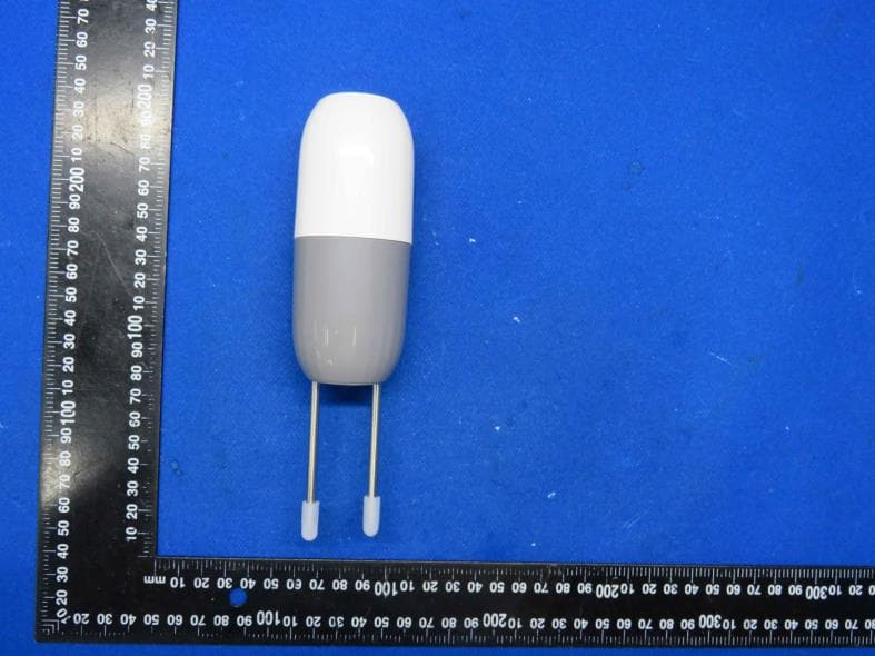
Click to zoom
Application Details
- Equipment Class
- DTS - Digital Transmission System
- Date of Grant
- Aug 28, 2024
- Application Purpose
- Original Equipment
- Date of Application
- Aug 28, 2024
- Equipment Note
- Intelligent soil sensor
- Frequency Range
- 2402.00000000 - 2480.00000000
- Country
- China
Documents & Files
Document Text
Text extracted from the exhibit documents filed with the FCC. Open a document above to read the original.
Users Manual
Solar Power Smart Water Valve User Manual (WiFi) Smart water valve features and user manual: Remote operation: Remote control by mobile phone APP anytime and anywhere; manual button for on-site operation and timing control Signal distance: Mainly depended on the distance of WiFi router , the open connection distance of smart water valve is ≤100 meters. Battery: Built-in long-life lithium-ion battery Protection level: IP65, the smart water valve can be installed and used outdoors 1 . The smart water valve is shipped out in a sleep mode by default. Before use, you need to long press button for 5 seconds to end the sleep mode. 2. The water valve connect WiFi directly. The signal strength is related to the range of the router. If the mobile phone can connect WiFi at the installation site, the water valve could also connect the WiFi. 3. The smart water valve needs to connect wifi of 2.4Ghz band, when pairing the network, make sure that the cell phone is connecting the 2.4Ghz WiFi 4. The smart water valve requires solar energy to supplement the power. Install the valve under the environment of sufficient sunlight . When it is lack of sunlights, use TYPE C port for charging battery 5. Once the battery is fully charged and no solar power supplyment, it can last 15 days on the premise of opening and closing valve once a day 6. Support 10 timing settings. After setting the timed programs, even it is offline, it will run on according to the program. 7. When automation task with soil sensor is activated, the timed program will be stopped 8. After the valve connect the soil sensor, the APP can display the soil temperature and humidity value. Users can set automatic irrigation task based on the temperature and humidity value. 9. Flowmeter operation requirements: The water flow rate range is 2~25 L/minute. Small water flow could not drive the flowmeter. large water flow will mislead meter to issue the false alarm of "water shortage warning" as the meter could not identify the flow size 10. Historical records will be only available when the smart water valve is online. 11. Water shortage reminder: if no water come out when the water valve is opened for 20 seconds, a water shortage warning pop out under the online status 12. If the battery is out of power when receiving the valve, you can place it under the sun or charge it via Type C cable 13. The Type-c interface is a power supply interface, the 5V/1A to 2A adapter is recommended 14. The rain and snow delay mode needs to be turned on manually. Once the rain and snow delay is on, the timed watering will not start until the rain and snow delay ends, then the timed irrigation resumes. 15. One smart water valve can work with one soil sensor, the communication is bluetooth, connecting distance is ≤10 M 16. Under the sleep mode, the smart water valve will not respond. Only use sleep mode when the valve is not used for a long time Instructions for use To better use the intelligent water valve, please read thefollowing usage instructions 1 . On-site operation 2Wi . Long press 5 seconds to connect iF 3. Long press 5 seconds to end sleep mode Smart water valve Button functions of smart water valve Inlet¾′′(DN20) Solar panel On-off button Networking /Activation button Product illustration Type-C charging port Indicator light Outlet¾′′(DN20) Rotate the timer, then you can see the Type-C port, adopting DC5V power adapter for Charging the built-in lithium-ion battery Solar panel Product nameSmart water valve Model QT-08W Communication protoco WiFi - 2.4Ghz Valve size ¾(DN20)′′ Waterproof levelIP65 Water pressure 0.2~8bar Solar panel rotation angle 0~30° Flowmeter Measuring range 2L~25L/min Specification Product nameSoil sensor Model QT-10S Power supply3 1.5V A pcs Adry battery Waterproof level IP65 Water content range 0~100% Water content accuracy 0~50%(±3%),50~100%(±5%) Temperature measuring range -5~60°C Temperature accuracy ±1°C Download App Scan QR code to download and install★ ★Mobile App store search:Smart life , click download and Register a member account ★Input your mobile phone number or email address ★Receive the verification code SMS, Configurate your own password. Download smart life or Tuya smart App, Register a member account Smart water valve networking tutorial APP Operation Guide 1.WiFi mobile phone connect with WiFi 2.4Ghz 2.Press and hold the switch button of the intelligent water valve for 5 seconds to enter the network connection state (the indicator light flashes) 3.Open the APP, click Add Device or the "+" in the upper right corner to add device 4.The APP automatically searches for devices and selects the device to be added. 5. Added successfully Smart water valve connects to humidity and temperature soil sensor Smart water valve sleep mode 1.The device is set to sleep mode by factory default. In sleep mode, the device will not be usable and needs to be activated for normal use; Activation method: Press and hold the smart water valve button for 5 seconds to activate the device 2.Set the sleep mode: When the device is not used for a long time, you can set the sleep mode. Please use the sleep mode with caution during normal use, because you need to manually press the button to activate and resume use. There are two ways to set sleep mode: 1.Turn on the sleep mode switch on the APP 2.Press and hold the smart water valve button for more than 15 seconds 1.Open the APP to the smart water valve interface and click Add Sensor. 2.Open the sensor housing, install the battery, press and hold the button for 5 seconds, the internal indicator light will flash.Enter the network configuration state. 3.Click to start searching (the sensor is within 5 meters of the smart water valve during network distribution). 4.Added successfully Smart phone APP interface Detailed explanation of user interface Irrigation time: Timing the duration of watering Irrigation water volume:Real time measurement of irrigation water volume Add sensors Display the detected temperature…
Text truncated - open the document above for the full version.
Attestation Statements
Shenzhen Power-Tomorrow Actuator Valve Co.,Ltd. 5th Floor, Building A, Mingjinhai industrial park, 1st Street, Gushu Hongwan, Bao'an District Shenzhen China Federal Communications Commission Authorization and Evaluation Division Equipment Authorization Branch 7435 Oakland Mills Road Columbia, MD 21046 2024-8-28 To whom it may concern: We, Shenzhen Power-Tomorrow Actuator Valve Co.,Ltd., hereby certify that the equipment for which authorization is sought (FCC ID: 2BEJK-QT-10S) is not “covered” equipment prohibited from receiving an equipment authorization pursuant to § 2.903 of the FCC rules. We also certify that, as of the date of the filing of the application, we are not identified on the Covered List (https://www.fcc.gov/supplychain/coveredlist) as an entity producing “covered” equipment. By signing this form, we confirm the above and that we are aware of the application requirements listed under § 2.911(b) and (d)(5) and (6). The information provided in this letter is based on the referenced rule parts of Title 47 of the CFR as well as KDB 986446 D01. Sincerely, Signature Qianmin Lu Manager Shenzhen Power-Tomorrow Actuator Valve Co.,Ltd. 62_[model] CoveredEqu_2.911(d)(5)(i) and (ii) - U, V03
Cover Letter(s)
CONFIDENTIALITY REQUEST for Certification Service in USA Federal Communication Commission Equipment Authorization Division, Application Processing Branch 7435 Oakland Mills Road Columbia, MD 21046 Date:<2024-8-28> Pursuant to Paragraphs §0.457 and 0.459 of the Commission’s Rules (47 C.F.R.) and Section §552(b)(4) of the Freedom of Information Act, we requests confidentiality for the following products: FCC ID Model name 2BEJK-QT-10S QT-10S For the product stated above, we request that the following information be held confidential; Exhibits Long-Term Confidentiality Short-Term Confidentiality Short-Term Confidentiality Days External Photos Internal Photos Block Diagram Schematics Test Setup Photos User’s Manual Parts List Tune Up Operational Descriptions The long-term confidentiality exhibits contain our trade secrets and proprietary information that could be of benefit to our competitors. The short-term confidentiality on the basis of ensuring that business sensitive information remains confidential until the actual marketing of our new device. If you have any questions, please feel free to contact me at the address shown below. Sincerely, Name/Title: Qianmin Lu/Manager Company: Shenzhen Power-Tomorrow Actuator Valve Co.,Ltd. Address: 5th Floor, Building A, Mingjinhai industrial park, 1st Street, Gushu Hongwan, Bao'an District Shenzhen China Phone: 13603034005 Fax: N/A E-Mail: [email protected]
Cover Letter(s)
Shenzhen Power-Tomorrow Actuator Valve Co.,Ltd. 5th Floor, Building A, Mingjinhai industrial park, 1st Street, Gushu Hongwan, Bao'an District Shenzhen China Federal Communications Commission Authorization and Evaluation Division Equipment Authorization Branch 7435 Oakland Mills Road Columbia, MD 21046 2024-8-28 To whom it may concern: We, the undersigned, hereby authorize Eurofins Product Service GmbH to act on our behalf in all matters relating to applications for equipment authorization FCC ID: 2BEJK-QT-10S including the signing of all documents related to these matters. Any and all acts carried out by Eurofins Product Service GmbH on our behalf shall have the same effect as acts of our own. By signing this application form, we agree to Eurofins’ current valid General Terms and Conditions (AGB),Testing and Certification Regulations (PZO) which can be viewed on following website www.eurofins.de/ee or retrieved on request. We also hereby certify that no party to this application is subject to a denial of benefits, including FCC benefits, pursuant to Section 5301 of the Anti-Drug Abuse Act of 1988, 21 U.S.C. 862. Sincerely, Name/Title: Qianmin Lu/Manager Company: Shenzhen Power-Tomorrow Actuator Valve Co.,Ltd. Address: 5th Floor, Building A, Mingjinhai industrial park, 1st Street, Gushu Hongwan, Bao'an District Shenzhen China Phone: 13603034005 Fax: N/A E-Mail: [email protected]
External Photos
Shenzhen HTT Technology Co., Ltd. Report No.: HTT202407731 Shenzhen HTT Technology Co.,Ltd. Tel: 0755-23595200 Fax: 0755-23595201 1F, Building B, Huafeng International Robotics Industrial Park,Hangcheng Road, Nanchang Community, Xixiang Street, Bao'an District, Guangdong Province, Shenzhen, China Page 1 of 3 Product Name: Intelligent soil sensor Model No.: QT-10S EUT Constructional Details External Photo Report No.: HTT202407731 Shenzhen HTT Technology Co.,Ltd. Tel: 0755-23595200 Fax: 0755-23595201 1F, Building B, Huafeng International Robotics Industrial Park,Hangcheng Road, Nanchang Community, Xixiang Street, Bao'an District, Guangdong Province, Shenzhen, China Page 2 of 3 Report No.: HTT202407731 Shenzhen HTT Technology Co.,Ltd. Tel: 0755-23595200 Fax: 0755-23595201 1F, Building B, Huafeng International Robotics Industrial Park,Hangcheng Road, Nanchang Community, Xixiang Street, Bao'an District, Guangdong Province, Shenzhen, China Page 3 of 3 ------End------
ID Label/Location Info
Label and Location Size: L: 2.0cm*W: 0.8cm Label and Location FCC ID : 2BEJK-QT-10S
Internal Photos
Shenzhen HTT Technology Co., Ltd. Report No.: HTT202407731 Shenzhen HTT Technology Co.,Ltd. Tel: 0755-23595200 Fax: 0755-23595201 1F, Building B, Huafeng International Robotics Industrial Park,Hangcheng Road, Nanchang Community, Xixiang Street, Bao'an District, Guangdong Province, Shenzhen, China Page 1 of 3 Product Name: Intelligent soil sensor Model No.: QT-10S EUT Constructional Details Internal Photo Report No.: HTT202407731 Shenzhen HTT Technology Co.,Ltd. Tel: 0755-23595200 Fax: 0755-23595201 1F, Building B, Huafeng International Robotics Industrial Park,Hangcheng Road, Nanchang Community, Xixiang Street, Bao'an District, Guangdong Province, Shenzhen, China Page 2 of 3 ANTENNA Report No.: HTT202407731 Shenzhen HTT Technology Co.,Ltd. Tel: 0755-23595200 Fax: 0755-23595201 1F, Building B, Huafeng International Robotics Industrial Park,Hangcheng Road, Nanchang Community, Xixiang Street, Bao'an District, Guangdong Province, Shenzhen, China Page 3 of 3 ------End------
RF Exposure Info
RF Exposure evaluation FCC ID: 2BEJK-QT-10S Exposure category: General population/uncontrolled environment EUT Type: Production Unit Device Type: Mobile Device 1. Reference According to §1.1307(b)(1), systems operating under the provisions of this section shall be operated in a manner that ensures that the public is not exposed to radio frequency energy level in excess of the Commission’s guidelines. According to §1.1310 and §2.1091 RF exposure is calculated. KDB447498 D01: Mobile and Portable Devices RF Exposure Procedures and Equipment Authorization Policies 2. Limit Limits for Maximum Permissible Exposure (MPE)/Controlled Exposure Frequency Range(MHz) Electric Field Strength(V/m) Magnetic Field Strength(A/m) Power Density (mW/cm²) Averaging Time (minute) Limits for Occupational/Controlled Exposure 0.3 – 3.0 3.0 – 30 30 – 300 300 – 1500 1500 – 100,000 614 1842/f 61.4 / / 1.63 4.89/f 0.163 / / (100) * (900/f 2 )* 1.0 f/300 5 6 6 6 6 6 Limits for Maximum Permissible Exposure (MPE)/Uncontrolled Exposure Frequency Range(MHz) Electric Field Strength(V/m) Magnetic Field Strength(A/m) Power Density (mW/cm²) Averaging Time (minute) Limits for Occupational/Controlled Exposure 0.3 – 3.0 3.0 – 30 30 – 300 300 – 1500 1500 – 100,000 614 824/f 27.5 / / 1.63 2.19/f 0.073 / / (100) * (180/f 2 )* 0.2 f/1500 1.0 30 30 30 30 30 F=frequency in MHz *=Plane-wave equivalent power density 3. MPE Calculation Method Predication of MPE limit at a given distance Equation from page 18 of OET Bulletin 65, Edition 97-01 S=PG/4πR² Where: S=power density P=power input to antenna G=power gain of the antenna in the direction of interest relative to an isotropic radiator R=distance to the center of radiation of the antenna 4. Antenna Information QT-10S can only use antennas certificated as follows provided by manufacturer; Antenna No. Model No. of antenna: Type of antenna: Gain of the antenna (Max.) Frequency range: BT / Chip Antenna 0.5dBi for 2400-2500MHz; 5. Manufacturing Tolerance BLE GFSK(Peak) Channel Channel 00 Channel 19 Channel 39 Target (dBm) 5.0 4.0 3.0 Tolerance ±(dB) 1.0 1.0 1.0 6. Standalone MPE Result As declared by the Applicant, the EUT is a wireless device used in a fix application, at least 20 cm from any body part of the user or nearby persons; from the maximum EUT RF output power, the minimum separation distance, r =20cm, as well as the gain of the used antenna is refer to section 4, the RF power density can be obtained. Modulation Type Output power Antenna Gain (dBi) Antenna Gain (linear) MPE (mW/cm 2 ) MPE Limits (mW/cm 2 ) dBm mW BLE 6.0 3.9811 0.5 1.2592 0.0010 1.0000 Remark: 1. Output power (Peak) including turn-up tolerance; 2. MPE evaluate distance is 20cm from user manual provide by manufacturer. 7. Conclusion The measurement results comply with the FCC Limit per 47 CFR 2.1091 for the uncontrolled RF Exposure of mobile device. ----------------THE END OF REPORT---------------
Test Report
Mini 2.45 GHz AntennaP/N 2450AT18A100 Detail Specification: Page 1 of 4 Inmm L±± W±± T a±± Function Feeding Point NC Need the layout file of the above? Contact us at: www.johansontechnology.com/en/ask-a-technical-question.html Johanson Technology, Inc. reserves the right to make design changes without notice. All sales are subject to Johanson Technology, Inc. terms and conditions. www.johansontechnology.com 4001 Calle Tecate • Camarillo, CA 93012 • TEL 805.389.1166 FAX 805.389.1821 Ver 1.3 2014 Johanson Technology, Inc. All Rights Reserved Note: It is recommended that the designer leave available slots for a "pi" (or shunt-series- shunt) network. The antenna matching network values here are used when antenna is mounted on Johanson's evaluation board. The matching values and topology on clinet's PCB will be different. Need our help tuning the antenna on your board? Contact our RF Applications Eng Team at: www.johansontechnology.com/component/techquestion Antenna Tuning services: www.johansontechnology.com/ipcantennaservices No. 1 2 0.0200.0120.500.30 Mounting ConsiderationsTerminal Configuration 0.0630.0081.600.20 0.051 +.004/-.008 1.30 +0.1/-0.2 Reel Quanity3,000 Mechanical Dimensions 0.1260.0083.200.20 Input Power2W max. (CW) Impedance50 Ω Operating Temperature-40 to +125°C Peak Gain0.5 dBi typ. (XZ-V) Average Gain-0.5 dBi typ. (XZ-V) Return Loss9.5 dB min. "High Frequency Ceramic Solutions" General Specifications Part Number2450AT18A100 Frequency Range2400 - 2500 Mhz 7/18/2014 1 2 L W a T * 2.6 4.2 1.6 1.9 0.4 2.7nH 1.0pF 3.9nH a) Without Matching Circuits b) With Matching Circuits Mount these devices with mark facing up. Units: mm * Line width should be designed to provide 50 Ω impedance matching characteristics. * Mini 2.45 GHz AntennaP/N 2450AT18A100 Detail Specification: Page 2 of 4 Test Board: P/N: 2450AT18A100-EB1SMA (orderable item) Return Loss with matching circuit @ +25 CVSWR with matching circuit @ +25C and +125C Johanson Technology, Inc. reserves the right to make design changes without notice. All sales are subject to Johanson Technology, Inc. terms and conditions. www.johansontechnology.com 4001 Calle Tecate • Camarillo, CA 93012 • TEL 805.389.1166 FAX 805.389.1821 Ver 1.3 2014 Johanson Technology, Inc. All Rights Reserved "High Frequency Ceramic Solutions" Typical Electrical Characteristics (T=25 o C) The antenna matching network values here are used when antenna is monted on Johanson's evaluation board. The matching values on clinet's PCB will be different. Go to: www.johansontechnology.com/ipcantennaservices and see how to obtain the new values. If you need further help, contact our RF Applications Eng Team at: 7/18/2014 GND 13.5mm 6.5mm 39.5mm6.5mm Matching Circuit No Ground 50Feed Line Antenna 19mm This 50ΩFeedline can be as short as needed, this lenth is just for reference to our EVB GND www.johansontechnology.com/component/techquestion Mini 2.45 GHz AntennaP/N 2450AT18A100 Detail Specification: Page 3 of 4 Johanson Technology, Inc. reserves the right to make design changes without notice. All sales are subject to Johanson Technology, Inc. terms and conditions. www.johansontechnology.com 4001 Calle Tecate • Camarillo, CA 93012 • TEL 805.389.1166 FAX 805.389.1821 Ver 1.3 2014 Johanson Technology, Inc. All Rights Reserved "High Frequency Ceramic Solutions" Typical Radiation Patterns at 2.45GHz (+25C) 7/18/2014 XY-V/XY-H 180° 270° 0° 90° X Z Y XY-cut scanning direction XY cut @2.45GHz Vertical Horizontal XZ-V/XZ-H YZ-V/YZ-H 180° 270° 0° 90° X Z Y XZ-cut scanning direction 180° 270° 0° 90° X Z Y YZ-cut scanning direction XZ cut @2.45GHz Vertical Horizontal YZ cut @2.45GHz Vertical Horizontal Mini 2.45 GHz AntennaP/N 2450AT18A100 Detail Specification: Page 4 of 4 Would you like Johanson Technology's RF team to help you design and tune our antenna on your board? Click on the link below: Johanson Technology, Inc. reserves the right to make design changes without notice. All sales are subject to Johanson Technology, Inc. terms and conditions. www.johansontechnology.com 4001 Calle Tecate • Camarillo, CA 93012 • TEL 805.389.1166 FAX 805.389.1821 Ver 1.3 2014 Johanson Technology, Inc. All Rights Reserved www.johansontechnology.com/technical-notes/msl-rating.html Suffix = S Suffix = E Suffix = S/E/R 2450AT18A100-EB1SMA (Page 2) Orderable item! www.johansontechnology.com/ipcsoldering-profile Antenna layout review, tuning, and characterization services www.johansontechnology.com/ipcantennaservices Packaging information www.johansontechnology.com/technical-notes/rohs-compliance.html Packaging Style Termination style RoHS Compliance MSL Info "High Frequency Ceramic Solutions" 7/18/2014 P/N Suffix Part Number Explanation Eg. 2450AT18A100R (MOQ Applies) Eg. 2450AT18A100(S, E, R) Soldering Information Evaluation Board(s) (1-port SMA antenna test boards) www.johansontechnology.com/ipcpackaging.html Bulk (loose pieces) 100% Tin (RoHS) T & R Tin / Lead T & R (Reverse)Suffix = R Please consult Factory Eg. 2450AT18A100S Eg. 2450AT18A100E AEC-Q2000 qualification available after special p/n: 2450AT18A100-AEC order. MOQ of 24K PCS applies for AEC and allow 16 weeks for AEC report leadtime. Recommneded Storage Condition and Max Shelf Life www.johansontechnology.com/ipcstorage-shelflife
Test Report
Shenzhen HTT Technology Co., Ltd. Report No.: HTT202407731F01 This results shown in this test report refer only to the sample(s) tested, this test report cannot be reproduced, except in full, without prior written permission of the company. The report would be invalid without specific stamp of test institute and the signatures of compiler and approver. Page 1 of 28 TEST Report Applicant: Shenzhen Power-Tomorrow Actuator Valve Co.,Ltd. Address of Applicant: 5th Floor, Building A, Mingjinhai industrial park, 1st Street, Gushu Hongwan, Bao'an District, Shenzhen, China. Manufacturer : Shenzhen Power-Tomorrow Actuator Valve Co.,Ltd. Address of Manufacturer : 5th Floor, Building A, Mingjinhai industrial park, 1st Street, Gushu Hongwan, Bao'an District, Shenzhen, China. Equipment Under Test (EUT) Product Name: Intelligent soil sensor Model No.: QT-10S Series model: N/A Trade Mark: N/A FCC ID: 2BEJK-QT-10S Applicable standards: FCC CFR Title 47 Part 15 Subpart C Section 15.247 Date of sample receipt: Jul. 26, 2024 Date of Test: Jul. 26, 2024 ~ Aug. 01, 2024 Date of report issued: Aug. 01, 2024 Test Result : PASS * * In the configuration tested, the EUT complied with the standards specified above. Report No.: HTT202407731F01 Shenzhen HTT Technology Co.,Ltd. Tel: 0755-23595200 Fax: 0755-23595201 1F, Building B, Huafeng International Robotics Industrial Park, Hangcheng Road,Nanchang Community, Xixiang Street, Bao'an District, Shenzhen, Guangdong, China Page 2 of 28 1. Version Version No. Date Description 00 Aug. 01, 2024 Original Tested/ Prepared By Date: Aug. 01, 2024 Project Engineer Check By: Date: Aug. 01, 2024 Reviewer Approved By : Date: Aug. 01, 2024 Authorized Signature Report No.: HTT202407731F01 Shenzhen HTT Technology Co.,Ltd. Tel: 0755-23595200 Fax: 0755-23595201 1F, Building B, Huafeng International Robotics Industrial Park, Hangcheng Road,Nanchang Community, Xixiang Street, Bao'an District, Shenzhen, Guangdong, China Page 3 of 28 2. Contents Page 1. VERSION ........................................................................................................................................................ 2 2. CONTENTS .................................................................................................................................................... 3 3. TEST SUMMARY ........................................................................................................................................... 4 4. GENERAL INFORMATION ............................................................................................................................ 5 4.1. GENERAL DESCRIPTION OF EUT ................................................................................................................ 5 4.2. TEST MODE ............................................................................................................................................... 7 4.3. DESCRIPTION OF SUPPORT UNITS .............................................................................................................. 7 4.4. DEVIATION FROM STANDARDS .................................................................................................................... 7 4.5. ABNORMALITIES FROM STANDARD CONDITIONS ........................................................................................... 7 4.6. TEST FACILITY ........................................................................................................................................... 7 4.7. TEST LOCATION ......................................................................................................................................... 7 4.8. ADDITIONAL INSTRUCTIONS ........................................................................................................................ 7 5. TEST INSTRUMENTS LIST ........................................................................................................................... 8 6. TEST RESULTS AND MEASUREMENT DATA ........................................................................................... 9 6.1. CONDUCTED EMISSIONS ............................................................................................................................ 9 6.2. CONDUCTED OUTPUT POWER .................................................................................................................. 10 6.3. CHANNEL BANDWIDTH .............................................................................................................................. 11 6.4. POWER SPECTRAL DENSITY ..................................................................................................................... 13 6.5. BAND EDGES ........................................................................................................................................... 15 6.5.1 Conducted Emission Method .......................................................................................................... 15 6.5.2 Radiated Emission Method ............................................................................................................. 16 6.6. SPURIOUS EMISSION ................................................................................................................................ 18 6.6.1 Conducted Emission Method .......................................................................................................... 18 6.6.2 Radiated Emission Method ............................................................................................................. 20 6.7. ANTENNA REQUIREMENT .......................................................................................................................... 27 7. TEST SETUP PHOTO .................................................................................................................................. 28 8. EUT CONSTRUCTIONAL DETAILS ..............................................................…
Text truncated - open the document above for the full version.
Test Setup Photos
Shenzhen HTT Technology Co., Ltd. Report No.: HTT202407731 Shenzhen HTT Technology Co.,Ltd. Tel: 0755-23595200 Fax: 0755-23595201 1F, Building B, Huafeng International Robotics Industrial Park,Hangcheng Road, Nanchang Community, Xixiang Street, Bao'an District, Guangdong Province, Shenzhen, China Page 1 of 1 Product Name: Intelligent soil sensor Model No.: QT-10S Test Setup Photo Radiated Emission ------End------
Contact Information
Applicant
Qianmin Lu
Test Firm
Shenzhen HTT Technology Co.,Ltd.Kevin Yang
[email protected]86-755-23595200
Technical Specifications
| # | Rule Parts | Frequency Range | Power Output |
|---|---|---|---|
| 1 | 15C | 2.40 GHz - 2.48 GHz | 3.30 mW |
Other Applications from Shenzhen Power-Tomorrow Actuator Valve Co.,Ltd.
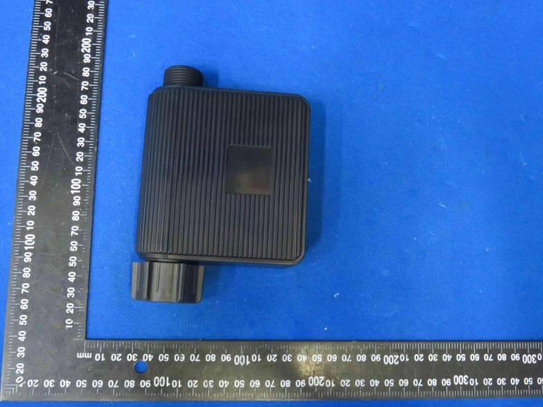
2BEJK-QT-08W
Aug 28, 2024Smart Valve
Equipment Class
DTS - Digital Transmission System