Text extracted from the exhibit documents filed with the FCC. Open a document above to read the original.
Please make sure that the Switch has turned on the wired connection mode. (Setting - Controllers and Sensors - Pro Controller Wired Communication) Attaching the controllers to the Switch will connect them automatically. Buttons can be set A / B / X / Y /R / ZR / L / ZL / L3 / R3 / D-Pad and left or right joysticks (joystick counts as eight keys). Seting Hold the M button and press any of M1/M2/L4/R4 button to enter the programming mode. Then input the button or button combination you want to set. *Each programmed button(M1/M2/L4/R4 can record up to 16 inputs (Each press of function buttons is regarded as an input) When the input exceeds 16 timesthe programming will automatically end. When you’re done , press the M1/M2/L4/R4 button that was pressed earlier to end the programming. Note: The controller will vibrate when you start or end the programming. Press the Home button or the Screenshot button to reconnect the Switch, The LED1-4 indicators on the side will start to flash in a regular pattern as an indication of reconnecting. This device complies with part 15 of the FCC Rules. Operation is subject to the following two conditions: (1) this device may not cause harmful interference, and (2) this device must accept any interference received, including interference that may cause undesired operation.Any changes or modifications not expressly approved by the party responsible for compliance could void the user's authority to operate the equipment. NOTE: This equipment has been tested and found to comply with the limits for a Class B digital device, pursuant to Part 15 of the FCC Rules. These limits are designed to provide reasonable protection against harmful interference in a residential installa- tion.This equipment generates, uses and can radiate radio frequency energy and, if not installed and used in accordance with the instructions, may cause harmful interference to radio communications.However, there is no guarantee that interference will not occur in a particular installation. If this equipment does cause harmful interference to radio or television reception,which can be determined by turning the equipment off and on, the user is encouraged to try to correct the interference by one or more of the following measures: -- Reorient or relocate the receiving antenna. -- Increase the separation between the equipment and receiver. -- Connect the equipment into an outlet on a circuit different from that to which the receiver is connected. -- Consult the dealer or an experienced radio/TV technician for help. The device has been evaluated to meet general RF exposure requirement. The device can be used in portable exposure condition without restriction Welcome Guide JC02-1 -+ ScreenshotHome L3 D-Pad Y X A B R3 L ZL R ZR MotorMotor TurboTurbo SR SL LED 1-4 ParingParing SR SL LED 1-4 R4 L4 Light Mapping M2 Charging port M1 Working voltage: DC3.7-4.2V Input voltage/current: DC5V/1A Charging time: about 2 hours Continuous running time: >8 hours Battery capacity: 600mAh Wake Up After the first successful connection, press the Home button to wake up the switch and reconnect (other buttons can not wake up). Power Off To power off the controller, press and hold the Pairing button for 0.5s. Low Battery When the battery power is low, the LED1-4 indicators lights flash quickly at the same time. Charge ChargingThe LED1-4 indicators lights slowly and Charge lamp will turn red. FullThe LED1-4 indicators lights off and Charge lamp will turn green. Charge lamp Change Colors Press the Light button once to change the color succes- sively.(Controller will vibrate) Colors: pink - red - orange - green - blue - cyan Change Modes Double press the Light button to switch light modes. (Controller will vibrate) Mode 1: Single Color Mode 2: Automatic Single Color Mode 3: Rainbow Mode 4: Lights Off Brightness Adjustment Press and hold the Light button for 1s to start adjusting the brightness: 40%-70%-100% (Controller will vibrate) Lights Off After switching the lights to Rainbow Mode, double press the light button to turn off the lights. Cancel Method A: After entering the programming mode, directly press the M1/M2/L4/R4 button that was pressed earlier to exit without setting any buttons.(at this timeM1/M2/L4/R4 button is empty and there is no function) Method B: Press the M button for 5s to reset the assaign function. Note: The controller will vibrate when you cancel the programming. Buttons can be set A / B / X / Y / L / ZL /R / ZR / D-Pad / M1/ M2 / L4 / R4. Seting Hold the Turbo button and press the button that you want to set to turn on the turbo function. (Controller will vibrate) Cancel Method A: Hold the Turbo button and press the button that you have set to turn off its turbo function. (Controller will vibrate) Method B: Hold the Turbo button for 4s to cancel the Turbo function of all buttons.(Controller will vibrate) Press the Motor button once to change the vibration of controller successively.(Controller will vibrate) Levels of vibration intensity: 0%50%, 100%. The controllers will remain paired when you detach them from the Switch, and you'll be able to use them wirelessly.
Attestation Statements (January 30, 2024) TO: Federal Communications Commission Authorization and Evaluation Division 7435 Oakland Mills Road Columbia, MD 21046, USA RE: Attestation Statements Part 2.911(d)(7) request for (FCC ID: 2BEV8-JC02 ) (Shenzhen Binpo Trading Co., Ltd), the undersigned, hereby authorize (NEWENERGYER LIMITED) to act as our designated U.S. agent for service of process, (Shenzhen Binpo Trading Co., Ltd) accepts to maintain an agent for no less than one year after the grantee has terminated all marketing and importation or the conclusion of any Commission-related proceeding involving the equipment. (NEWENERGYER LIMITED) accepts the responsibility to act as designated U.S. agent for service of process, provides an agent for no less than one year after the grantee has terminated all marketing and importation or the conclusion of any Commission-related proceeding involving the equipment. Applicant Information: Company name: Shenzhen Binpo Trading Co., Ltd Contact Name: Wei Haiyi Address: No. 16, 617, Sanhe Overseas Chinese Second District, Tongsheng Community, Dalang Str eet, Longhua District, Shenzhen, China Telephone No: 13538214502 Email: [email protected] FRN: 0034835595 Signature [Wei Haiyi] U.S. Agent Information: Company Name: NEWENERGYER LIMITED Address: 1818 S Patton Ct, Denver, CO, 80219 Contact Name: CHUN LIU Telephone No: 213 289 5042 Email: [email protected] FRN: 0034665885 Signature [CHUN LIU]
(Shenzhen Binpo Trading Co., Ltd) (January 30, 2024) Eurofins Electrical and Electronic Testing NA, Inc. 914 West Patapsco Avenue Baltimore, MD 21230 RE: Attestation Statements Part 2.911(d)(5)(i) request for (FCC ID: 2BEV8-JC02) [Shenzhen Binpo Trading Co., Ltd] (“the applicant”) certifies that the equipment for which authorization is sought is not “covered” equipment prohibited from receiving an equipment authorization pursuant to section 2.903 of the FCC rules. Sincerely, (Applicant signature) (Applicant printed name) Wei Haiyi (Shenzhen Binpo Trading Co., Ltd) (January 30, 2024) Eurofins Electrical and Electronic Testing NA, Inc. 914 West Patapsco Avenue Baltimore, MD 21230 RE: Attestation Statements Part 2.911(d)(5)(ii) request for (FCC ID: 2BEV8-JC02) [Shenzhen Binpo Trading Co., Ltd] (“the applicant”) certifies that, as of the date of the filing of the application, the applicant is not identified on the Covered List as an entity producing “covered” equipment. Sincerely, (Applicant signature) (Applicant printed name) Wei Haiyi
Shenzhen Binpo Trading Co., Ltd (January 30, 2024) Eurofins Electrical and Electronic Testing NA, Inc. 914 West Patapsco Avenue Baltimore, MD 21230 RE: CONFIDENTIALITY REQUEST FOR (Epoch Game Controller / JC02 / FCC ID: 2BEV8-JC02) To Whom It May Concern: This letter serves as an official request for confidentiality under sections 0.457 and 0.459 of CFR 47. We have requested that the Exhibits Long-Term Confidentiality Short-Term Confidentiality NOTE 2 ID Label/Location No No Attestation Statement No No External Photos No ☐ Block Diagram ☒ ☐ Schematics ☒ ☐ Test Report No No Test Setup Photos No ☐ User’s Manual ☐ NOTE 1 ☒ Internal Photos ☐ NOTE 1 ☒ Parts List / Tune Up ☐ ☐ RF Exposure Info No No Operational Description ☒ ☐ Cover Letter(s) No No SDR Software / Security Info ☐ No required to be submitted with this application be permanently withheld from public review. Above mentioned document contains detailed system and equipment description are considered as proprietary information in operation of the equipment. The public disclosure of above documents might be harmful to our company and would give competitor an unfair advantage in the market. Please contact me if there is any information you may need. Sincerely, Signature: Name: Wei Haiyi Title: Project assistant
Shenzhen Binpo Trading Co., Ltd (January 30, 2024) Eurofins Electrical and Electronic Testing NA, Inc. 914 West Patapsco Avenue Baltimore, MD 21230 RE: LETTER OF AGENT AUTHORIZATION To Whom It May Concern: We, the undersigned, hereby authorize (Shenzhen CTB Testing Technology Co., Ltd.) to act on our behalf in all matters relating to application for equipment authorization, including the signing of all documents relating to these matters. We also hereby certify that no party to the application authorized hereunder is subject to the denial of benefits, including FCC benefits, pursuant to Section 5301 of the Anti-Drug Abuse Act of 1988, 21 U.S.C.853(a). This agreement expires one year from the current date. Sincerely, Signature: Name: Wei Haiyi Title: Project assistant
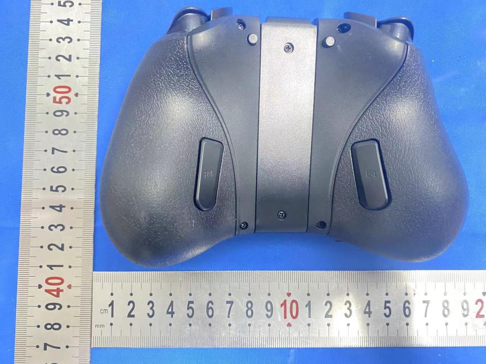
Shenzhen CTB Testing Technology Co., Ltd. Report Tel: 4008-707-283 Web: http://www.ctb-lab.net Page 1 of 4 Model: JC02 External Photos Shenzhen CTB Testing Technology Co., Ltd. Report Tel: 4008-707-283 Web: http://www.ctb-lab.net Page 2 of 4 Shenzhen CTB Testing Technology Co., Ltd. Report Tel: 4008-707-283 Web: http://www.ctb-lab.net Page 3 of 4 Shenzhen CTB Testing Technology Co., Ltd. Report Tel: 4008-707-283 Web: http://www.ctb-lab.net Page 4 of 4
FCC ID LABEL: Label Location: FCC ID: 2BEV8-JC02 Model No.: JC02
Shenzhen CTB Testing Technology Co., Ltd. Report Tel: 4008-707-283 Web: http://www.ctb-lab.net Page 1 of 5 Model: JC02 Internal Photos Shenzhen CTB Testing Technology Co., Ltd. Report Tel: 4008-707-283 Web: http://www.ctb-lab.net Page 2 of 5 Shenzhen CTB Testing Technology Co., Ltd. Report Tel: 4008-707-283 Web: http://www.ctb-lab.net Page 3 of 5 Shenzhen CTB Testing Technology Co., Ltd. Report Tel: 4008-707-283 Web: http://www.ctb-lab.net Page 4 of 5 ANT Shenzhen CTB Testing Technology Co., Ltd. Report Tel: 4008-707-283 Web: http://www.ctb-lab.net Page 5 of 5
Shenzhen CTB Testing Co., Ltd. FCC ID: 2BEV8-JC02 Portable device According to §15.247(e)(i) and §1.1307(b)(1), systems operating under the provisions of this section shall be operated in a manner that ensures that the public is not exposed to radio frequency energy level in excess of the Commission’s guidelines. According to KDB447498 D01 General RF Exposure Guidance V06 The 1-g SAR and 10-g SAR test exclusion thresholds for 100 MHz to 6 GHz at test separation distances ≤ 50 mm are determined by: [(max. power of channel, including tune-up tolerance, mW)/(min. test separation distance, mm)]·[√f(GHZ)] ≤ 3.0 for 1-g SAR and ≤ 7.5 for 10-g extremity SAR, where: • f(GHZ) is the RF channel transmit frequency in GHz • Power and distance are rounded to the nearest mW and mm before calculation • The result is rounded to one decimal place for comparison When the minimum test separation distance is < 5 mm, a distance of 5 mm is applied to determine SAR test exclusion. BLE: Modulation Channel Freq. (GHz) Conduct ed power (dBm) Conducte d power (mW) Tune-up power (dBm) Max tune-up power (dBm) Max tune-up power (mW) Distance (mm) Result calculatio n SAR Exclusion threshold SAR test exclusion 2.402 3.134 2.06 3±1 4.00 2.51 <5 0.77860 3.00 YES 2.44 2.542 1.80 2±1 3.00 2.00 <5 0.62334 3.00 YES 2.480 2.883 1.94 2±1 3.00 2.00 <5 0.62843 3.00 YES GFSK Conclusion: For the max result : 0.77860≤ FCC Limit 3.0 for 1g SAR.
SHENZHEN ALANTE TECHNOLOGY CO LTD 113 Day line sex can measuring PDF pdfFactory Pro www.fineprint.cn SHENZHEN ALANTE TECHNOLOGY CO LTD 213 APPlications ※Bluetooth Home RF ※ISM band 2.4GHz applications 1.Dimensions PDF pdfFactory Pro www.fineprint.cn SHENZHEN ALANTE TECHNOLOGY CO LTD 313 2.Specifications number Item Specifications 1 Working Central Frequency 2441 MHz 2 Band Width (2402-2480)MHz 3 Gain 3dBi 4 VSWR ≤2.0 5 Antenna type PCB antenna 6 Azimuth Beam width Omni‐directional 7 Impedance 50欧姆 8 Modulation mode GFSK 3. Instrument testing, software simulation parameters ①VSWR Mkr1: 2397MHz 1.47 Mkr2: 2450MHz 1.51 Mkr3: 2482 MHz 1.59 PDF pdfFactory Pro www.fineprint.cn SHENZHEN ALANTE TECHNOLOGY CO LTD 413 ②Smith Char Mkr1: 2397MHz 73.4 Mkr2: 2450MHz 62.7 Mkr3: 2482MHz 66.8 PDF pdfFactory Pro www.fineprint.cn SHENZHEN ALANTE TECHNOLOGY CO LTD 513 ③Return Loss Mkr1: 2397MHz -15 Mkr2: 2450MHz -18 Mkr3: 2482 MHz -16 PDF pdfFactory Pro www.fineprint.cn SHENZHEN ALANTE TECHNOLOGY CO LTD 613 ④Smith Char The simulation Mkr1: 2400MHz 1.234 Mkr2: 2500MHz 1.051 Mkr3: 2600MHz 1.322 PDF pdfFactory Pro www.fineprint.cn SHENZHEN ALANTE TECHNOLOGY CO LTD 713 ⑤Return Loss The simulation Mkr1: 2400MHz -19.59 Mkr2: 2450MHz -27.70 Mkr3: 2500MHz -31.97 Mkr4: 2550MHz -21.83 PDF pdfFactory Pro www.fineprint.cn SHENZHEN ALANTE TECHNOLOGY CO LTD 813 ⑥Phase The simulation Mkr1: 2400MHz -54.89 Mkr2: 2500MHz -82.03 Mkr3: 2600MHz -102.6 PDF pdfFactory Pro www.fineprint.cn SHENZHEN ALANTE TECHNOLOGY CO LTD 913 4. Radiation Pattems XY-plane PDF pdfFactory Pro www.fineprint.cn SHENZHEN ALANTE TECHNOLOGY CO LTD 1013 XZ-plane PDF pdfFactory Pro www.fineprint.cn SHENZHEN ALANTE TECHNOLOGY CO LTD 1113 YZ-plane PDF pdfFactory Pro www.fineprint.cn SHENZHEN ALANTE TECHNOLOGY CO LTD 1213 3D Radiation field type PDF pdfFactory Pro www.fineprint.cn SHENZHEN ALANTE TECHNOLOGY CO LTD 1313 PDF pdfFactory Pro www.fineprint.cn Manufacturer: Shenzhen Binpo Trading Co., Ltd Address: No. 16, 617, Sanhe Overseas Chinese Second District, Tongsheng Community, Dalang Street, Longhua District, Shen zhen, China
TEST REPORT Compiled by: Reviewed by: Approved by: Zhou Kui Arron Liu Bin Mei / Director Note: If there is any objection to the inspection results in this report, please submit a written report to the company within 15 days from the date of receiving the report. The test report is effective only with both signature and specialized stamp. This result(s) shown in this report refer only to the sample(s) tested. Without written approval of Shenzhen CTB Testing Technology Co., Ltd. this report can’t be reproduced except in full. The tested sample(s) and the sample information are provided by the client. “*” indicates the testing items were fulfilled by subcontracted lab. “#” indicates the items are not in CNAS accreditation scope. Product Name: Epoch Game Controller FCC ID: 2BEV8-JC02 Trademark: N/A Model Number: JC02 Prepared For: Shenzhen Binpo Trading Co., Ltd Address: No. 16, 617, Sanhe Overseas Chinese Second District, Tongsheng Community, Dal ang Street, Longhua District, Shenzhen, China Manufacturer: Shenzhen Binpo Trading Co., Ltd Address: No. 16, 617, Sanhe Overseas Chinese Second District, Tongsheng Community, Dal ang Street, Longhua District, Shenzhen, China Prepared By: Shenzhen CTB Testing Technology Co., Ltd. Address: 1&2/F., Building A, No.26, Xinhe Road, Xinqiao, Xinqiao Street, Bao'an District, Shenzhen, Guangdong, China Sample Received Date: Dec. 19, 2023 Sample tested Date: Dec. 19, 2023 to Dec. 27, 2023 Issue Date: Dec. 27, 2023 Report No.: CTB231227026RFX Test Standards FCC Part15.247 ANSI C63.10:2013 Test Results PASS Remark: This is Bluetooth radio test report. Shenzhen CTB Testing Technology Co., Ltd. Report No.: CTB231227026RFX Report Tel: 4008-707-283 Web: http://www.ctb-lab.net Page 2 of 35 TABLE OF CONTENT Test Report Declaration Page 1. VERSION ........................................................................................................................................ 3 2. TEST SUMMARY ........................................................................................................................... 4 3. MEASUREMENT UNCERTAINTY ................................................................................................. 5 4. PRODUCT INFORMATION AND TEST SETUP ............................................................................ 6 4.1 Product Information .......................................................................................................................... 6 4.2 Test Setup Configuration .................................................................................................................. 6 4.3 Support Equipment........................................................................................................................... 6 4.4 Channel List ..................................................................................................................................... 7 4.5 Test Mode ........................................................................................................................................ 7 4.6 Test Environment ............................................................................................................................. 7 5. TEST FACILITY AND TEST INSTRUMENT USED ....................................................................... 8 5.1 Test Facility ...................................................................................................................................... 8 5.2 Test Instrument Used ....................................................................................................................... 8 6. AC POWER LINE CONDUCTED EMISSION ................................................................................ 10 6.1 Block Diagram Of Test Setup ......................................................................................................... 10 6.2 Limit ................................................................................................................................................ 10 6.3 Test procedure ............................................................................................................................... 10 6.4 Test Result ..................................................................................................................................... 12 7. RADIATED SPURIOUS EMISSION ............................................................................................. 14 7.1 Block Diagram Of Test Setup ......................................................................................................... 14 7.2 Limit ................................................................................................................................................ 14 7.3 Test procedure ............................................................................................................................... 15 7.4 Test Result ..................................................................................................................................... 16 8. BAND EDGE AND RF COUNDUCTED SPURIOUS EMISSIONS ............................................... 23 8.1 Block Diagram Of Test Setup ......................................................................................................... 23 8.2 Limit ................................................................................................................................................ 23 8.3 Test procedure ............................................................................................................................... 23 8.4 Test Result ..................................................................................................................................... 24 9. COUDUCTED OUTPUT POWER ................................................................................................. 26 9.1 Block Diagram Of Test Setup ................................................…
Text truncated - open the document above for the full version.
Shenzhen CTB Testing Technology Co., Ltd. Report Tel: 4008-707-283 Web: http://www.ctb-lab.net Page 1 of 2 Model: JC02 Radiated Emission Below 1G Above 1G Shenzhen CTB Testing Technology Co., Ltd. Report Tel: 4008-707-283 Web: http://www.ctb-lab.net Page 2 of 2 Conducted emissions
| # | Rule Parts | Frequency Range | Power Output |
|---|---|---|---|
| 1 | 15C | 2.40 GHz - 2.48 GHz | 2.06 mW |