2BEZP600138LoRa wireless transmitters
Enless Wireless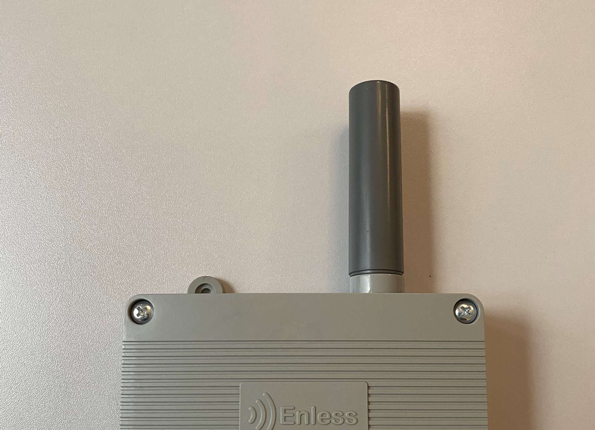
Click to zoom
Application Details
- Equipment Class
- DSS - Part 15 Spread Spectrum Transmitter
- Date of Grant
- Aug 01, 2024
- Application Purpose
- Original Equipment
- Date of Application
- Aug 01, 2024
- Equipment Note
- LoRa wireless transmitters
- Frequency Range
- 902.30000000 - 914.90000000
- Company
- Enless Wireless
- Country
- France
Documents & Files
Document Text
Text extracted from the exhibit documents filed with the FCC. Open a document above to read the original.
Users Manual
Autonomy of batteries Battery autonomy based on transmission periodicities Battery autonomy is given by the file below: ~ Battery_autonomy.pdf 103KB pdf ! Product storage before use = 6 months maximum Battery replace.ment Below is a table showing the battery reference to use for each sensor. Typé Sensor TXT&HAMB 600- 021/600-121 TXCO2VOC T&H AMB 600- 023/600-123 TXTEMP INS 600- 031/600-131 TXTEMP CONT1 600- 032/600-132 TXTEMP CONT2 600- 232/600-332 TXT&H EXT 600- 034/600-134 TX 4/20 600- 035/600-135 BatteryC 1000-028 (ER26500) X BatteryD 1000-029 (ER34615) BatteryD 1000-030 (ER34615} X Battery 1000- (ER34 X X X X X ) Type Battery C BatteryD Battery D Batte TX PULSE 600- X 036/600-136 TX PULSE ATEX X 600-037 TX PULSE LED 600- X 038/600-138 TXCONTACT 600- X 039/600-139 ! Risk of explosion if sensor batteries are replaced with an incorrect reference. Battery replacement procedure Ambient sensors 1 . Disconnect the Molex connector of the used battery from the PCB connector 2. Remove the used battery from its slot 3. lnsert the new battery in the slot 4. Reconnect the new battery Molex connector to the PCB connector S. The sensor restarts. Rugged sensors 1 . Disconnect the used battery Molex connector from the PCB connector 2. Unscrew the screws on the battery clip 3. Remove the battery clip 4. Remove the used battery from its slot 5. lnsert the new battery in the slot 6. Replace the battery clip 7. Secure the battery clip with the two screws provided 8. Reconnect the new battery Molex connector to the PCB connector 9. The sensor restarts. Do not throw the battery into the fire. Do not short-circuit the battery. Do not crush the battery. CE declaration ~ DT 38 -CE DECLARATION OF CONFORMITY.pdf 111KB pdf Contact Enless Wireless 6 bis, rue du Temple 33000 Bordeaux FRANCE Installation guide LoRaWAN Installation help guide Learn how to configure products in LoRaWAN mode This document details the installation procedure for Enless sensors in LoRaWAN mode Good· practices 1. Expo.rt the document to PDf .. We know that when you work on site you do not always have access to the internet. For your on-site installations we recommend that you export this installation guide in pdf format. Ta do this please click on the t hree action buttons on the top right corner of this page, then click on Export to PDF. n mode L ~ Export as PDF r1' Copyllnk un , nt:. t"J,U.ac • • • • • • riécess 2. Do some testing! If this is your first time using Enless products, we recommend carrying out a test setup/installation in your office before moving on to the final on-site installation. This will no longer be necessary once you are familiar with the installation procedure. About LoRaWAN Reminder regarding LoRaWAN mode LoRaWAN technology is bidirectional, and allows: Transmission of frames from the sensor to a network (uplinks) Transmission of information from the network to the sensor (downlink) End-to-end encryption of data exchanged (AES128) When used in LoRaWAN mode, the sensors can send their data to a public (operator) or private LoRaWAN (gateway) network. LoRaWAN architecture USE LORAWAN PUBLIC OPERATED NETWORK BUILO YOUR LORAWAN PRIVATE NETWORK LoRaWA.N Gateway '- ....... '- 1 ~-rr-1 k>T Pfatfonn Network Server • • • • 1 Installation steps Steps for installing Enless sensors in LoRaWAN mode Installation steps Sensors• provlsioning Declaratlon of sensors on the LoRaWAN network Validation of the LED behavior Valldatlon of the sensor LED behavlor Validation of data reception Valldatlon that the sensors communlcate correctly wlth the LoRaWAN network Activation of sensors Powerlng the sensors so that they communicate with the LoRaWAN network Configuration of downllnks Creatlon and sendlng of conflguratlon downllnks Posltloning and fixing the sensors Installation of sensors on site following our best practlces. Information concerning the sensors More information about Enless sensors and their behavior LoRaWAN class: class A Frequency used: 868MHz LoRaWAN version : V1.0.2revB Activation : OTAA Activation keys: DEVEUI, APPEUI, APPKEY Managing Join requests and the ADR Join equests • When powered up, the transmitters perform a JOIN request. • After 24Hr, they send a LinkCheckReq message that needs to be confirmed with a LinkCheckAck. And so on every 24 hours. When the LinkCheckReq has been confirmed with a LinkCheckAck, the transmitter will not send another JOIN request. • If the LinkCheckReq message does not receive a LinkCheckAck response, further LinkCheckReq messages will be sent. If 6x LinkCheckReq messages do not receive a response, the transmitter will then initiate a new JOIN procedure. ADR (Adaptive Data Rate) When the transmitter initiates a JOIN request for the first time, the Spreading Factor is fixed at SF12 and BW1.25. The transmitter wiU not change its SF unless it receives a LinkADRReq from the gateway, requesting it to use a different SF parameter Installation Sensors• provisioning Declare sensors on your LoRaWAN network LoRaWAN Enless sensors use OTAA (Over The Air Activation) activation mode. For their OTAA activation, Enless sensors have LoRaWAN keys: • DEVEUI : Transmitter identifier • APPEUI : Global application identifier • APPKEY : Transmitter application key These activation keys are made available in three possible ways: 1 - On the labels on the back of the sensors 2 - By scanning the QR codes of the sensors 3 - ln CSV format The activation keys for your LoRaWAN Enless sensors can be provided in .csv format by our Sales Administration department. Plesse contact [email protected] Activation of sensors Power the sensors so they pair with the LoRaWAN network. Once the transmitters have been declared using the keys on the cloud or the gateway, the LoRaWAN transmitters must be powered up ta dialogue with the network. Verify that the transmitters are in LoRaWAN mode. Validate t hat the jumper of each transmîtter is correctly positioned on a single pin and that it is in LoRaWAN mode {see appendlx). lf'this is net…
Text truncated - open the document above for the full version.
Users Manual
Installation guide LoRa proprietary Installation help guide Learn how to configure products in proprietary LoRa mode Whether for use with a Modbus receiver or with a BACnet receiver, the product configuration principle is identical. Vou will find on the left of this document the details of the steps to follow. i We recommend following the setup steps one by one. Good practices 1. Export. the document to PDF 1 We know that when you work on site you do not always have -acc1:?ss to the internet. For your on-site installations we recommend that you export this installation guide in pdf format. To do this please click on the three action buttons cm the top right corner of this page, then click on Export to PDF. n mode Le @ Export as PDF <fl Copylink UN • nt~ r'.MUC. 1 L • • • • • • riècess 2. Do some testing! If this is your first time using Enless products, we recommend carrying out a test setup/installation in your office before moving on to the final on-site installation. This wlll no longer be necessary once you are famil.îar with the installation procedure. About proprietary LoRa Reminder regarding proprietary LoRa mode Proprietary ·LoRa architecture ln proprietary LoRa, the sensors communicate with an Enless receiver (Modbus or BACnet). The receiver stores the sensor data and makes it available t o a PLC/BMS. ) ) ) PLC "' ) • .,. ) ➔➔➔➔➔➔➔➔'» '» IP Network D ) ~ Data process1ng With the Modbus receiver RX MODBUS 500-302 Enless sensors send thelr information to the receiver. The latter stores the data received ln a Modbus Table. lt 1s then connected to the BMS vla Modbus TCP/IP or RTU. With the BACnet receiver RX BACNET 500-312 Enless sensors send their informatlon to the recelver. The latter converts the data lnto BACnet objects. lt ls then connected to the BMS vla BACnet IP or MSTP. One receiver can manage up to 50 Enless sensors Differences between LoRaWAN and Enless proprietary LoRa LoRaWAN vs LoRa proprietary: what differences? a If you wish to use the sensors in LoRaWAN mode, please refer to the LoRaWAN mode installation help guide. Installation steps Installation Steps and required materials Installation steps IP Configuration Configure the PC's IP settlngs to be able to access the recelver's conflguratlon server. Configuring sensors Declaration and configuration of the sensors you wish to pair wlth the receiver. Data reception Val dating that the sensors communicate correctly with the recelver and that the RSSI is good. Server access Preparatlon of the receiver (antenna, power supply) before accessi ng the configuration server. Activation of sensors Powering the sensors so that they pa1lr with the recelver and recover their configuration parameters. Installation of devices Installation of devices on site followlng our best practlces. Receiver settings Configuration of recelver communication parameters before connectlng to the BMS Connection to PLC Guide to connectlng and wirlng your recelver to the PLC/BMS. The TX 10 600-040 and TX MODBUS 600-041 have specific installation procedures. Please refer to the summary for installation procedures for these products. Necessary material PC with ethernet port Use an ethernet/USB adapter if your PC does not have an ethernet port Power supply for the receiver Power the recelver wlth 7.5 to 24VDC. Enless 12V power supply avallable Ref1 POWER 1000-002 Long range antenna for the receiver Use the Enless Long Range Antenna Refi ANT REN SMA LR 1000-008 Screwdriver 1x Phllllps screwdrlver 1x fiat scre'Ndrlver (121 2.5mm) Installation IP Configuration Configure your PC's IP settings to access the receiver's configuration server The configuration of the sensors wlll be done from the server embedded in the receiver. lt will therefore be necessary for you to be able to access the configuration interface of your RX MOBDUS or RX BACNET. The receiver configuration server is accessible at the address 192.168.77.77 Configuring IP settings from your PC On your PC, configure the IP settings so that the configuration server is accessible. A , Victor Petit -- C ....,_ -r,' -.. - - ,.... .,.,, .... ""' Example of IP settings • IP address: 192.168.77.2 • Subnet prefix length: 24 • Default gateway: 192.168.77.1 • Preferred ONS: 8.8.8.8 • Subnet mask (if available): 255.255.255.0 Once these settings are configured, the configuration server IP should be accessible from your browser at 192.168.77.77 (please avoid use on Microsoft Edge and favor use on Google Chrome). Vou can now move on to the next step. This configuration is also valid for access ta the configuration servers of the TX 10 800-040 and TX MODBUS 800-041. Access to the server Prepare your receiver and access the configuration server Receiver preparation v Step 1 : Connect an antenna to the recelver First of all, don't forget to connect the long-range antenna (ref: ANT REN SMA LR 868MHz 1000-008) to the SMA connecter of the receiver. v Step 2 : Power the receiver (7.5 - 24VDC) 1. Open the receiver case by unscrewing the 4 caver screws. 2. Externally power your receiver (between 7.5 and 24VDC). If yau use our 12V power supply, connect your power supply to the POWER terminal of the receiver. • Red wire connected to the V+ terminal black • Black wire connected to the 0V terminal black The LED C should light up when your receiver is properly powered. Consumption is normally less than 50mA at 12V. During the sensor installation phase, there may be peaks at 500mA. To avoid any problems please maintain 1A 12V on the power terminal black -v Step 3 : Connect the recelver vla Ethernet to the PC The receiver is supplied without RJ45 cable. Vou need to obtain an RJ45 cable to continue the installation. Connect the RJ45 cable to the port on your receiver and also to the Ethernet port on your PC. If your PC does not have an Ethernet port, we invite you to use a USB / Ethernet adapter. -v Step 4 : Valldate the recelver LED behavlor Once your receiver is powered and connected to your PC, you can validate the correct beh…
Text truncated - open the document above for the full version.
Attestation Statements
Federal Communications Commission Bordeaux, July 1 st 2024 Authorization and Evaluation Division 7435 Oakland Mills Road Columbia, MD 21046 USA Subject: Attestation Statements Part 2.911(d)(5)(i) Filing Applicant: Enless Wireless FCC ID: 2BEZP600138 Enless Wireless (“the applicant”) certifies that the equipment for which authorization is sought is not “covered” equipment prohibited from receiving an equipment authorization pursuant to section 2.903 of the FCC rules. Sincerely, Théo BENISSAN, July 1 st 2024
Attestation Statements
Federal Communications Commission Bordeaux, July 1 st 2024 Authorization and Evaluation Division 7435 Oakland Mills Road Columbia, MD 21046 USA Subject: Attestation Statements Part 2.911(d)(5)(ii) Filing Applicant: Enless Wireless FCC ID: 2BEZP600138 Enless Wireless (“the applicant”) certifies that, as of the date of the filing of the application, the applicant is not identified on the Covered List (as a specifically named entity or any of its subsidiaries or affiliates) as an entity producing “covered” equipment. Sincerely, Théo BENISSAN, July 1 st 2024
Attestation Statements
Enless Wireless 45 ter Avenue de Verdun 33520 Bruges FRANCE Date: July 1 st 2024 Federal Communications Commission Authorization and Evaluation Division 7435 Oakland Mills Road Columbia, MD 21046 FCC ID: 2BEZP600138 US Agent – Attestation Statement / Part 2.911(d)(7) Enless Wireless certifies, that as of June 6 th 2024, we have designated FCC US Agent, LLC to accept service of process on our behalf for FCC ID: 2BEZP600138. Enless Wireless, accepts to maintain an agent of service of process in the United States for no less than one year after either the grantee has permanently terminated all marketing and importation of the applicable equipment within the U.S., or the conclusion of any Commission- related administrative or judicial proceeding involving the equipment, whichever is later. FCC US Agent, LLC, accepts as of the date of the filing of this application, the obligation of being the designated agent for the purpose of accepting service of process on behalf of Enless Wireless for FCC ID: 2BEZP600138. Designated Agent Information: Company Name: FCC US Agent, LLC FRN: 0033402884 Address: 3722 Illinois Avenue, Saint Charles, IL, 60174, USA Contact Person: Tim Payne Phone: 708-571-3148 Email: [email protected] Sincerely, Company: Enless Wireless FRN: 0034924324 Designated Agent: FCC US Agent, LLC Designated Agent Representative: Tim Payne Company Representative: Théo BENISSAN Signature: Signature:
Cover Letter(s)
Bordeaux, July 1 st 2024 Subject: RADIO Certification of 600-138 product Applicant: Enless Wireless Product (PMN): 600-138 Model (HVIN): 600138402 FCC ID: 2BEZP600138 To Whom It May Concern: We would like to submit the above product for Certification concerning ISED rules for a new single certification. Please review all required documents enclosed. This application is for LoRa wireless transmitter. Compliance for RF exposure requirement is demonstrated in test report. If you have any queries, please do not hesitate to contact us. Regards, Théo BENISSAN, July 1st 2024
Cover Letter(s)
Federal Communications Commission Authorization and Evaluation Division Bordeaux, July 1 st 2024 Subject: Confidentiality Request regarding application for certification of FCC ID: 2BEZP600138 Applicant: Enless Wireless Product: 600-138 Model: 600138402 To Whom It May Concern: Pursuant to Sections 0.457 and 0.459 of the Commission’s Rules, we hereby request confidential treatment of information accompanying this application as outlined below: Exhibit Type File Name Block Diagram Schematics Operational Description Parts List 600-138 BlkDia 600-138 Schem 600-138 Opdes 600-138 PartsLst The above materials contain trade secrets and proprietary information not customarily released to the public. The public disclosure of these materials may be harmful to the applicant and provide unjustified benefits to its competitors. The applicant understands that pursuant to Section 0.457 of the Rules, disclosure of this application and all accompanying documentation will not be made before the date of the Grant for this application. If you have any queries, please do not hesitate to contact us. Regards, Théo BENISSAN, July 1st 2024
Cover Letter(s)
Attn: TIMCO Engineering Inc. 13146 NW 86th Drive Suite 400 A lachua, Florida 32615 Authority to Act as Agent On our behalf, I appoint M. Olivier HEYER from Emitech Montpell ier – 145 rue du Massacan – 34740 VENDARGUES FRANCE, to a ct as our agen t in the preparation of this application for equipment certification. I certify that submitted documents properly describe the de vice or system for wh ich equipment certification is sought. I also certify tha t each unit manufactured, imported or marketed, as defined in the Fede ral Communications Commission’s regulations will have affixed to it a label identical to tha t submitted for approval with this application. For instances where our authorized agent signs the application for certification on our beha lf, I acknowledge tha t all responsibility for complying with the terms and conditions for certification, as specified by TIMCO Engineering Inc. , still resides with Enless Wireless - 45 ter avenue de Verdun , 33520 Bruges, FRANCE. This authorization is valid until further written notice from Enless Wireless. The July 16 th 2024 By Théo BENISSAN, Technical Manager
External Photos
External photos Product (PMN): 600-138 Model (HVIN): 600138402 Front (600-138) without cable Back (600-138) without cable Left (600-138) without cable Right (600-138) without cable Top (600-138) without cable Bottom (600-138) without cable General view 600-138
ID Label/Location Info
Label sample Product (PMN): 600-138 Model (HVIN): 600138402 Label 1 On the box TX PULSE LED 600-138 350xxxxx 6 cm 2 cm Label 2 On the right side of the device TX PULSE LED 600-138 350xxxxx 2.5 cm 1.4 cm ID LORA : xxxxxxxx EN VX.XX.XX Serial number(8 digits) QR Code Serial number(8 digits) Firmwareversion Label 3 At the back of the device LORAWAN CODES DevEUI : 70B3D54FD0XXXXXX 6 cm 2 cm Label 4 On the top side of the device 32 digits 6 digits AppEUI : 70B3D54FD0000000 AppKey : XXXXXXXXXXXXXXXXXXXXXXXXXXXXXXXX 2.5 cm 1.4 cm QR Code PMN : 600-138 HVIN : 600138402 FCC ID : 2BEZP600138 IC ID : 32107-600138 FCC and ISED information
ID Label/Location Info
Label location Product (PMN): 600-138 Model (HVIN): 600138402 Label 1 On the box Label 2 On the right side of the device Label 3 At the back of the device Label 4 On the top side of the device
Internal Photos
Internalphotos Product (PMN): 600-138 Model (HVIN): 600138402 Internal view without cable and connector PCB top without cable and connector PCB bottom without cable and connector Antenna Antenna PCB bottom without cable, connector and shield Antenna Internal view (600-138)
RF Exposure Info
Siège Social : Emitech - 3, avenue des Coudriers - Z.A. de l’Observatoire - 78180 MONTIGNY LE BX - France Siret : 344 545 645 00022 - Tél. : 33 (0)1 30 57 55 55 - Fax : 33 (0)1 30 43 74 48 - E-mail : [email protected] - URL : www.emitech.fr SAS au capital de 1 560 000 € - R.C.S. VERSAILLES 344 545 645 - APE 7112B RE-EVE-23B292-3A Ed.0 Duplication of this test report is only permitted for an integral photographic facsimile. It includes the number of pages referenced here above. This document is the result of testing a specimen or a sample of the product submitted. It does not imply an assessment of the conformity of the whole manufactured products of the tested sample. Test report issued under the responsibility of: EMITECH MONTPELLIER laboratory MRA US-EU Designation Number: FR0006 Canadian CAB Identifier: FR0003 RF EXPOSURE TEST REPORT KDB 447498 D01 V06 RSS-102 - Issue 5, March 2015 Company ....................................... : ENLESS WIRELESS Address. .......................................... : 45 TER AVENUE DE VERDUN 33520 BRUGES FRANCE Test item description. .................. : LoRa temperature & humidity wireless transmitter Trade Mark. .................................... : ENLESS WIRELESS Manufacturer................................... : ENLESS WIRELESS Model/Type reference. .................... : 600138402 / TX PULSE LED 600-138 FCC ID. ........................................... : 2BEZP600138 IC. ................................................... : 32107-600138 Ratings. ........................................... : 3.6 Vdc to 3.8 Vdc Testing Laboratory ....................... : EMITECH MONTPELLIER laboratory Address. .......................................... : 145 rue de Massacan 34740 VENDARGUES FRANCE Report Reference No. ................... : RE-EVE-23B292-3A Test procedure. .............................. : FCC IC Certification Diffusion. ......................................... : Mr PETIT Applicant’s name. ........................... : ENLESS WIRELESS Date of issue. .................................. : July 19, 2024 Total number of pages. ................... : 10 Revision. ......................................... : 0 Compiled by. ................................... : Olivier HEYER Approved by (+ signature). ............. : David MONTAULON (Technical Manager) RE-EVE-23B292-3A Ed.0 Page 2 on 10 REPORT INDEX: 1. GENERAL INFORMATIONS .......................................................................................................................... 3 2. REFERENCE DOCUMENT(S) ........................................................................................................................ 4 3. EQUIPMENT TECHNICAL DESCRIPTION .................................................................................................... 5 3.1. TEST CONDITIONS ................................................................................................................................... 5 3.2. E.U.T. MARKING PLATE ........................................................................................................................... 5 3.3. E.U.T. GENERAL VIEW ............................................................................................................................. 6 3.4. E.U.T. FRONT VIEW ................................................................................................................................. 6 3.5. E.U.T. BACK VIEW ................................................................................................................................... 7 3.6. E.U.T. INTERNAL VIEW & ELECTRONIC BOARD .......................................................................................... 7 3.7. E.U.T. MECHANICAL AND ELECTRICAL DESIGN .......................................................................................... 8 3.8. E.U.T. INPUT/OUTPUT PORTS................................................................................................................... 8 3.9. EUT RADIO SPECIFICATIONS .................................................................................................................... 9 4. RF EXPOSURE .............................................................................................................................................10 4.1. DSSS MODE .........................................................................................................................................10 4.2. FHSS MODE .........................................................................................................................................10 REVISION HISTORY: Revision Date Modified pages Modifications 0 July 19, 2024 / Creation RE-EVE-23B292-3A Ed.0 Page 3 on 10 1. GENERAL INFORMATIONS This document submits the results of Radio tests performed on the equipment Connected measuring device TX PULSE LED 600-138 (denominated hereafter E.U.T.: equipment under test) according to document(s) listed in §2 of this test report. TESTING PROCEDURE AND TESTING LOCATION: Testing Location ....................................... : EMITECH MONTPELLIER laboratory Address. ..................................................... : 145 rue de Massacan 34740 VENDARGUES FRANCE Test procedure. .......................................... : FCC IC Certification Tested by .................................................... : Morgan PATEY Test supervisor ........................................... : None Date of receipt of test item ......................... : N/A Date (s) of performance of tests ................. : From November 22 nd of 2023 to January 10 th of 2024 APPLICANT'S GENERAL INFORMATIONS: Company name ......................................... : ENLESS WIRELESS Company address. ..................................... : 45 TER AVENUE DE VERDUN 33520 BRUGES FRANCE Person(s) present during the tests. ............ : No representative for company attended the tests. Responsible. ..................................…
Text truncated - open the document above for the full version.
Test Report
Siège Social : Emitech - 3, avenue des Coudriers - Z.A. de l’Observatoire - 78180 MONTIGNY LE BX - France Siret : 344 545 645 00022 - Tél. : 33 (0)1 30 57 55 55 - Fax : 33 (0)1 30 43 74 48 - E-mail : [email protected] - URL : www.emitech.fr SAS au capital de 1 560 000 € - R.C.S. VERSAILLES 344 545 645 - APE 7112B RR-EVE-23B292-5A Ed.0 Duplication of this test report is only permitted for an integral photographic facsimile. It includes the number of pages referenced here above. This document is the result of testing a specimen or a sample of the product submitted. It does not imply an assessment of the conformity of the whole manufactured products of the tested sample. LIST OF ACCREDITED SITES AND SCOPE AVALAIBLE ON WWW.COFRAC.FR TESTING ACCREDITATIONS N° 1-0826, 1-0827, 1-1925, 1-2069,1-2070, 1-2206, 1-2376 & 1-6086 Test report issued under the responsibility of: EMITECH MONTPELLIER laboratory MRA US-EU Designation Number: FR0006 Canadian CAB Identifier: FR0003 RADIO TEST REPORT FCC 47 CFR PART 15 RSS-247_Issue 3 RSS-Gen Issue 5 ANSI C 63.10: 2013 Company ......................................... : ENLESS WIRELESS Address............................................. : 45 TER AVENUE DE VERDUN 33520 BRUGES FRANCE Test item description. .................... : LoRa wireless transmitter Trade Mark. ...................................... : ENLESS WIRELESS Manufacturer. ................................... : ENLESS WIRELESS Model/Type reference. ...................... : 600138402 / TX PULSE LED 600-138 FCC ID. ............................................. : 2BEZP600138 IC. ..................................................... : 32107-600138 Ratings.............................................. : 3.6 Vdc to 3.8 Vdc Testing Laboratory ......................... : EMITECH MONTPELLIER laboratory Address............................................. : 145 rue de Massacan 34740 VENDARGUES FRANCE Report Reference No. ..................... : RR-EVE-23B292-5A Test procedure. ................................ : FCC IC Certification Diffusion. ........................................... : Mr PETIT Applicant’s name. ............................. : ENLESS WIRELESS Date of issue. .................................... : July 19, 2024 Total number of pages. ..................... : 49 Revision. ........................................... : 0 Compiled by. ..................................... : Morgan PATEY Approved by (+ signature). ............... : David MONTAULON (Technical Manager) RR-EVE-23B292-5A Ed.0 Page 2 on 49 REPORT INDEX: 1. GENERAL INFORMATIONS .......................................................................................................................... 3 2. REFERENCE DOCUMENT(S) ........................................................................................................................ 4 3. EQUIPMENT TECHNICAL DESCRIPTION .................................................................................................... 5 3.1. TEST CONDITIONS ................................................................................................................................... 5 3.2. E.U.T. MARKING PLATE ........................................................................................................................... 5 3.3. E.U.T. MODIFICATION(S).......................................................................................................................... 5 3.4. E.U.T. GENERAL VIEW ............................................................................................................................. 6 3.5. E.U.T. FRONT VIEW ................................................................................................................................. 6 3.6. E.U.T. BACK VIEW ................................................................................................................................... 7 3.7. E.U.T. INTERNAL VIEW & ELECTRONIC BOARD........................................................................................... 7 3.8. E.U.T. MECHANICAL AND ELECTRICAL DESIGN .......................................................................................... 8 3.9. E.U.T. INPUT/OUTPUT PORTS ................................................................................................................... 8 3.10. EUT RADIO SPECIFICATIONS .................................................................................................................... 9 4. RESULT SUMMARY ..................................................................................................................................... 10 5. MEASUREMENT UNCERTAINTY ................................................................................................................ 12 6. TEST CONDITIONS AND RESULTS ........................................................................................................... 13 6.1. RADIATED EMISSION LIMITS..................................................................................................................... 13 6.2. NUMBER OF CHANNELS, 20 DB BANDWIDTH, AND AVERAGE TIME OF OCCUPANCY ...................................... 27 6.3. EQUIVALENT ISOTROPIC RADIATED POWER ...........................................................................…
Text truncated - open the document above for the full version.
Contact Information
Applicant
Theo Benissan(Technical Manager)
Test Firm
EMITECH MontpellierOlivier HEYER
Technical Specifications
| # | Rule Parts | Frequency Range | Power Output |
|---|---|---|---|
| 1 | 15C | 902.3 MHz - 914.9 MHz | 8.55 mW |
Other Applications from Enless Wireless
2BEZP600501
Aug 26, 2024LoRa wireless transmitters
Equipment Class
DTS - Digital Transmission System
2BEZP600123
Jul 18, 2024LoRa CO2, VOC, temperature & humidity wireless transmitter
Equipment Class
DSS - Part 15 Spread Spectrum Transmitter
2BEZP600121
Jul 04, 2024LoRa temperature & humidity wireless transmitter
Equipment Class
DTS - Digital Transmission System