2BF4W-FC04HEARING AIDS
ELEHEAR.Inc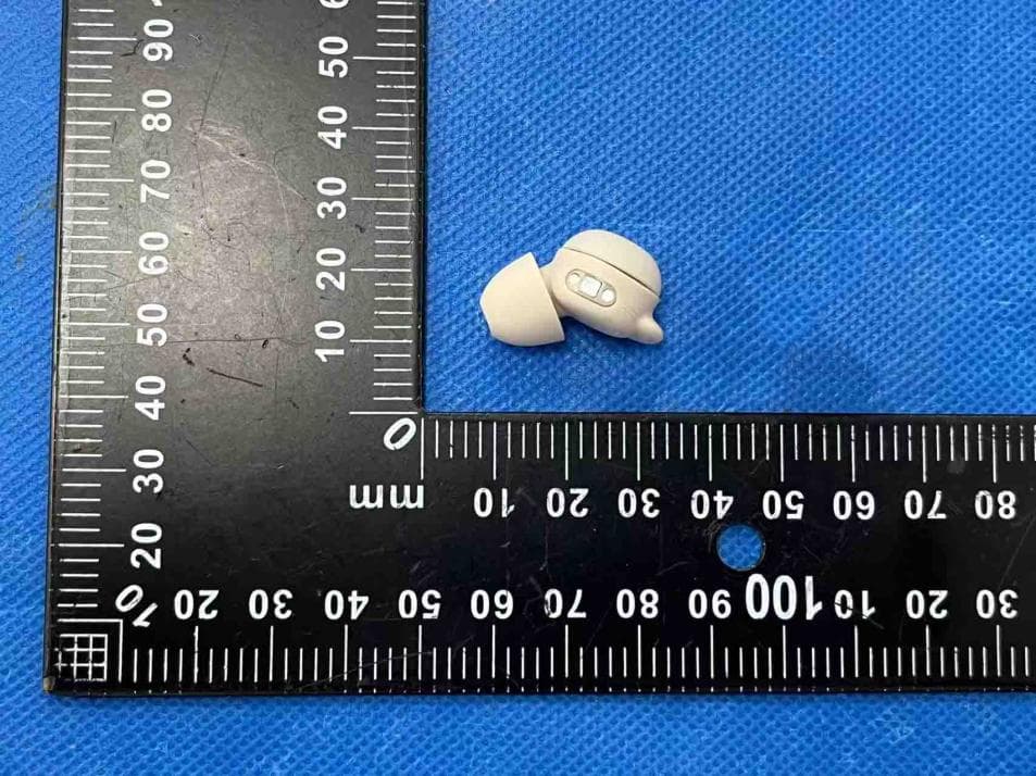
Click to zoom
Application Details
- Equipment Class
- DSS - Part 15 Spread Spectrum Transmitter
- Date of Grant
- Nov 18, 2025
- Application Purpose
- Original Equipment
- Equipment Note
- HEARING AIDS
- Frequency Range
- 2402.00000000 - 2480.00000000
- Company
- ELEHEAR.Inc
- Country
- China
Documents & Files
Document Text
Text extracted from the exhibit documents filed with the FCC. Open a document above to read the original.
Users Manual
V 1.2 User Manual ELEHEAR-Delight OTC (888) 669-1099 ELEHEAR Inc. 708, Building 12, Shenzhen Bay Tech-Eco Park, Nanshan District Shenzhen Guangdong, China [email protected] WELCOME Thank you for choosing ELEHEAR Hearing Aids to enhance your hearing experience and improve your quality of life. These hearing aids are individually fitted and fine-tuned to meet your specific hearing needs; therefore, they are not suitable for use by others. Carefully and thoroughly read the user guide before using your hearing aids. It is essential to operate the devices according to the instructions provided. Improper handling may result in damage. Should you have any questions regarding the use or maintenance of your hearing aids, please do not hesitate to contact your hearing care professional. The hearing aids are covered by a limited warranty. Visit our website at https://elehear.com/policies/terms-of-service for detail of the limited PRODUCT WARRANTY 0102 INSTRUCTIONSFORUSE PRECAUTIONS FEEDBACK ACCESSORIES PRODUCT STRUCTURE OPERATION GUIDE MAINTENANCE AND CLEANING TROUBLESHOOTING GUIDE GENERAL WARNINGS TECHNICAL SPECIFICATIONS EXPLANATION OF GRAPHICAL SYMBOLS USEDINMEDICALDEVICELABELING FCCREQUIREMENT CYBERSECURITY PRODUCT WARRANTY CONTENTS 03 06 08 09 11 14 33 37 43 55 58 59 61 62 ELEHEAR Hearing Aids utilize the microphone to capture environmental sounds, which are then converted into electrical signals.These signals are transmitted to a digital chip within the hearing aids,where they undergo advanced processing, including filtering and amplification. The result is a clear and amplified electrical representation of the external sound. This processed signal is then delivered to the receiver (speaker) located in the earpiece, where it is converted back into acoustic sound waves. These sound waves travel through the middle ear to the inner ear, where they are detected by the auditory nerve and transmitted to the brain for sound perception. PRINCIPLES OF HEARING AIDS The primary components of hearing aids include the main unit (housing the microphone and speaker and battery), ear domes, and charging case. HEARING AIDS STRUCTURAL COMPONENTS Empirical fitting, for hearing compensation in patients with air-conducted hearing loss. HEARING AIDS SCOPE OF APPLICATION Individuals with acute external otitis, tympanitis, acute suppurative otitis media, chronic suppurative otitis media (in the stage of purulent infection), and those allergic to the materials of this product are not suitable for wearing. CONTRAINDICATIONS INSTRUCTIONS FOR USE 0304 1. Hearing conditions professionally examined and audiologically tested before, and hearing aids should be under the guidance of a doctor or a professional dispenser of hearing aids. 2. Pay attention to the moisture-proof, shock-proof, high-temperature-proof, light-proof, and drop-proof features of the products. 3. Never immerse your hearing aids in any liquid. Remove your hearing aids before swimming and washing your hair and showering; wait for the ear canal to dry after swimming or showering before putting on your hearing aids. 4. Avoid proximity to strong magnetic objects, as this may affect the sensitivity of the hearing aids. PRECAUTIONS Individuals under the age of 18 require specialized care. Using this device without a proper medical evaluation could potentially exacerbate hearing impairment or related conditions. It is essential that hearing aid users under 18 undergo a recent medical evaluation conducted by a qualified physician, preferably an ear, nose, and throat (ENT) specialist. The physician should assess and confirm whether the use of a hearing aid is appropriate prior to initiating use. INDIVIDUALS UNDER THE AGE OF 18 SHOULD CONSULT A PHYSICIAN BEFORE USING THIS PRODUCT 0506 5. If you feel uncomfortable during the use, please try to choose the appropriate ear cap replacement under the premise of comfort, or consult after-sales service. 6. Hearing aids surfaces should be kept clean and earwax should be removed from ear domes or other acoustic devices frequently. 7. You should correctly use the program and the volume switch to control the program. 8. Please use the accessories provided by our company or authorized dealers, the use of other accessories may affect the safety and effectiveness of the product. COMMON CAUSES OF ACOUSTIC FEEDBACK INCLUDE: New hearing aids users often experience an effect known as acoustic feedback, commonly referred to as "whistling." This occurs when amplified sound leaks out of the ear canal and is picked up by the hearing aids' microphone, creating a feedback loop. It is more likely to occur at higher volume settings. Excessive earwax buildup in the ear canal Improper hearing aids fit or placement Deterioration of hearing aids components over time Incorrect ear tip size or style Obstruction or compression of the hearing aids microphone FEEDBACK (ACOUSTIC FEEDBACK) 0708 ACCESSORIES Charging Case x1 Hearing Aid x2 Closed Domes ( S / M / L ) x2 Open Domes ( S / M / L ) x2 Ear Wings ( S / M / L ) x2 Multi-function Tool Pen x1 USB Type-C to USB-A Cable x1 Quick Start Guide x1User Manual x1 Quick Start Guide User Manual ELEHEAR Delight OTC ELEHEAR Delight OTC 0910 PRODUCT STRUCTURE ELEHEAR BEYOND PRO CHARGING CASE Charging Case Charging Indicator Reset Button Microphone 1 Power & Switch Button On / off, volume up / down Ear Dome 1112 Hearing Aids Charging Indicator Charging Port Protector Sound Hole Remove the protectors from the hearing aids before use Charging Contact OPERATION GUIDE It is recommended to fully charge both the charging case and hearing aids for 1.5 hours before initial use. CHARGING PRIOR TO FIRST USE The App enables you to set up and personalize your hearing aids according to your hearing preferences and manage its settings. Ensure that you download the App before using the product. (1) Open the web browser on your phone and go to: https://elehear.com/pages/app-page to download the App. YoucanalsousetheQRcodebel…
Text truncated - open the document above for the full version.
Attestation Statements
(ELEHEAR.Inc) (2025/8/28) Eurofins Electrical and Electronic Testing NA, Inc. 914 West Patapsco Avenue Baltimore, MD 21230 RE: Attestation Statements Part 2.911(d)(5)(i) request for (FCC ID: 2BF4W-FC04) [ELEHEAR.Inc] (“the applicant”) certifies that the equipment for which authorization is sought is not “covered” equipment prohibited from receiving an equipment authorization pursuant to section 2.903 of the FCC rules. We also certify that, as of the date of the filing of the application, the equipment does not utilize cyber-security or anti-virus software from Kaspersky Lab, Inc, or any of its successors and assignees, which is also on the “covered list”. Sincerely, (Applicant signature) (Applicant printed name) Jessie Zhang (ELEHEAR.Inc) (2025/8/28) Eurofins Electrical and Electronic Testing NA, Inc. 914 West Patapsco Avenue Baltimore, MD 21230 RE: Attestation Statements Part 2.911(d)(5)(ii) request for (FCC ID: 2BF4W-FC04) [ELEHEAR.Inc] (“the applicant”) certifies that, as of the date of the filing of the application, the applicant is not identified on the Covered List as an entity producing “covered” equipment. Sincerely, (Applicant signature) (Applicant printed name) Jessie Zhang
Cover Letter(s)
ELEHEAR.Inc Model Difference 2025/8/28 EUT NAME: HEARING AIDS Trademark: ELEHEAR MODEL: FC04 FC04A, FC04B, FC04C, FC04D, FC04E, FC04F, FC04G, FC04H, FC04I, FC04J, FC04K, FC04L, FC04M, FC04N, FC04O, FC04P, FC04Q, FC04R, FC04S, FC04T, FC04U, FC04V, FC04W, FC04X, FC04Y, FC04Z FCC ID: 2BF4W-FC04 All the models are the same circuit and RF module, except model names. Regards Sincerely Client’s signature: Client’s name / title : Jessie Zhang / PM Contact information / address: 708, Building 12, Shenzhen Bay Tech-Eco Park, Nanshan District, Shenzhen, China
Cover Letter(s)
ELEHEAR.Inc 2025/8/28 Eurofins Electrical and Electronic Testing NA, Inc. 914 W. Patapsco Avenue Baltimore, MD 21230 USA RE: CONFIDENTIALITY REQUEST FOR EUT NAME: HEARING AIDS Trademark: ELEHEAR MODEL: FC04 FC04A, FC04B, FC04C, FC04D, FC04E, FC04F, FC04G, FC04H, FC04I, FC04J, FC04K, FC04L, FC04M, FC04N, FC04O, FC04P, FC04Q, FC04R, FC04S, FC04T, FC04U, FC04V, FC04W, FC04X, FC04Y, FC04Z FCC ID: 2BF4W-FC04 To Whom It May Concern: This letter serves as an official request for confidentiality under sections 0.457 and 0.459 of CFR 47. We have requested that the - Block Diagram - Schematics - Operational Description required to be submitted with this application be permanently withheld from public review. The above materials contain trade secrets and proprietary information not customarily released to the public. The public disclosure of these materials may be harmful to the applicant and provide unjustified benefits to its competitors. Please contact me if there is any information you may need. Sincerely, Client’s signature: Client’s name / title : Jessie Zhang / PM Contact information / address: 708, Building 12, Shenzhen Bay Tech-Eco Park, Nanshan District, Shenzhen, China
Cover Letter(s)
ELEHEAR.Inc 2025/8/28 Eurofins Electrical and Electronic Testing NA, Inc. 914 W. Patapsco Avenue Baltimore, MD 21230 USA RE: LETTER OF AGENT AUTHORIZATION To Whom It May Concern: We, the undersigned, hereby authorize Shenzhen BCTC Testing Co., Ltd to act on our behalf in all matters relating to application for equipment authorization, including the signing of all documents relating to these matters. We also hereby certify that no party to the application authorized hereunder is subject to the denial of benefits, including FCC benefits, pursuant to Section 5301 of the Anti-Drug Abuse Act of 1988, 21 U.S.C.853(a). This agreement expires one year from the current date. Sincerely, Client’s signature: Client’s name / title : Jessie Zhang / PM Contact information / address: 708, Building 12, Shenzhen Bay Tech-Eco Park, Nanshan District, Shenzhen, China
External Photos
Report No.: BCTC2507865820E External Photos Report No.: BCTC2507865820E Report No.: BCTC2507865820E Report No.: BCTC2507865820E
ID Label/Location Info
Label Location: The product is too small to be assigned an FCC ID number, so it is placed in the user manual.
Internal Photos
Report No.: BCTC2507865820E Internal Photos Antenna Report No.: BCTC2507865820E Report No.: BCTC2507865820E
RF Exposure Info
RF EXPOSURE EVALUATION METHOD FCC ID: 2BF4W-FC04 Applicable standard: In accordance with FCC 47 CFR part 2 (2.1093) this device has been defined as a portable device which is defined as a transmitting device designed to be used so that the radiating structure(s) of the device is/are within 20 centimeters of the body of the user. Portable devices must be evaluated using the specified in FCC 47 CFR part 2 (2.1093) and ANSI/IEEEC95.1-1992. and had been tested in accordance with the measurement methods and procedures specified in IEEE 1528-2003. Per FCC KDB 447498 D01 v06, the 1-g and 10-g SAR test exclusion thresholds for 100 MHz to 6 GHz at test separation distances s 50 mm are determined by: SAR Test Exclusion Thresholds for 100 MHz – 6 GHz and ≤ 50 mm Approximate SAR Test Exclusion Power Thresholds at Selected Frequencies and Test Separation Distances are illustrated in the following Table. The 1-g and 10-g SAR test exclusion thresholds for 100 MHz to 6 GHz at test separation distances ≤ 50 mm are determined by: [(max. power of channel, including tune-up tolerance, mW)/(min. test separation distance, mm)] · [√f(GHz)] ≤ 3.0 for 1-g SAR and ≤ 7.5 for 10-g extremity SAR,where f(GHz) is the RF channel transmit frequency in GHz Power and distance are rounded to the nearest mW and mm before calculation The result is rounded to one decimal place for comparison The test exclusions are applicable only when the minimum test separation distance is ≤ 50 mm and for transmission frequencies between 100 MHz and 6 GHz. When the minimum test separation distance is < 5 mm, a distance of 5 mm is applied to determine SAR test exclusion. BLE Mode Frequency(MHz) Maximum Conducted Output Power(PK) (dBm) Conducted Output Power Limit(dBm) GFSK(1Mbps) 2402 -2.38 30 2440 -2.20 30 2480 -2.20 30 max possible output power (PK, conducted):-2±1dBm -1dBm=0.79mW 2402MHz [(max. power of channel, including tune-up tolerance, mW)/(min. test separation distance,mm)] · [√f(GHz)]= 0.79/5*√2.402=0.245≤3.0 2440MHz [(max. power of channel, including tune-up tolerance, mW)/(min. test separation distance,mm)] · [√f(GHz)]= 0.79/5*√2.440=0.247≤3.0 2480MHz [(max. power of channel, including tune-up tolerance, mW)/(min. test separation distance,mm)] · [√f(GHz)]= 0.79/5*√2.48=0.249≤3.0 BT Condition Mode Frequency (MHz) Conducted Power (dBm) Limit (dBm) Verdict NVNT 1-DH1 2402 -1.93 21 Pass NVNT 1-DH1 2441 -1.87 21 Pass NVNT 1-DH1 2480 -1.95 21 Pass NVNT 2-DH1 2402 -2.84 21 Pass NVNT 2-DH1 2441 -2.64 21 Pass NVNT 2-DH1 2480 -2.82 21 Pass NVNT 3-DH1 2402 -2.21 21 Pass NVNT 3-DH1 2441 -1.86 21 Pass NVNT 3-DH1 2480 -2.07 21 Pass max possible output power (PK, conducted):-1±1dBm 0dBm=1mW 2402MHz [(max. power of channel, including tune-up tolerance, mW)/(min. test separation distance,mm)] · [√f(GHz)]= 1/5*√2.402=0.310≤3.0 2441MHz [(max. power of channel, including tune-up tolerance, mW)/(min. test separation distance,mm)] · [√f(GHz)]= 1/5*√2.441=0.312≤3.0 2480MHz [(max. power of channel, including tune-up tolerance, mW)/(min. test separation distance,mm)] · [√f(GHz)]= 1/5*√2.48=0.315≤3.0 Conclusion: 1. [(max. power of channel, including tune-up tolerance, mW)/(min. test separation distance, mm)] * [√f(GHz)] < 3.0. 2. SAR Test Exclusion Thresholds is 3.0 for separation distance 5mm. Therefore, SAR test is not required.
Test Report
No.:BCTC/RF-ICT-005 Page: 1 of 85 Edition:C.0 TEST REPORT Shenzhen BCTC Testing Co., Ltd. Report No.: BCTC2507865820-1E Applicant: ELEHEAR.Inc Product Name: HEARING AIDS Test Model: FC04 Tested Date: 2025-07-31 to 2025-08-15 Issued Date: 2025-08-15 Report No.: BCTC2507865820-1E No.:BCTC/RF-ICT-005 Page: 2 of 85 Edition:C.0 FCC ID: 2BF4W-FC04 The test report is effective only with both signature and specialized stamp.This result(s) shown in this report refer only to the sample(s) tested. Without written approval of Shenzhen BCTC Testing Co., Ltd, this report can’t be reproduced except in full.The tested sample(s) and the sample information are provided by the client. Product Name: HEARING AIDS Trademark: ELEHEAR Model/Type Reference: FC04 FC04A, FC04B, FC04C, FC04D, FC04E, FC04F, FC04G, FC04H, FC04I, FC04J, FC04K, FC04L, FC04M, FC04N, FC04O, FC04P, FC04Q, FC04R, FC04S, FC04T, FC04U, FC04V, FC04W, FC04X, FC04Y, FC04Z Prepared For: ELEHEAR.Inc Address: 708, Building 12, Shenzhen Bay Tech-Eco Park, Nanshan District, Shenzhen, China Manufacturer: ELEHEAR.Inc Address: 708, Building 12, Shenzhen Bay Tech-Eco Park, Nanshan District, Shenzhen, China Prepared By: Shenzhen BCTC Testing Co., Ltd. Address: 1-2/F., Building B, Pengzhou Industrial Park, No.158, Fuyuan 1st Road, Zhancheng, Fuhai Subdistrict, Bao'an District, Shenzhen, Guangdong, China Sample Received Date: 2025-07-31 Sample Tested Date: 2025-07-31 to 2025-08-15 Issue Date: 2025-08-15 Report No.: BCTC2507865820-1E Test Standards: FCC Part15.247 ANSI C63.10:2013 Test Results: PASS Remark: This is Bluetooth Classic radio test report. Tested by: Approved by: Shanshan. Zhang / Project Handler Zero Zhou/Reviewer Report No.: BCTC2507865820-1E No.:BCTC/RF-ICT-005 Page: 3 of 85 Edition:C.0 Table Of Content Test Report Declaration Page 1. Version .................................................................................................................. 5 2. Test Summary ....................................................................................................... 6 3. Measurement Uncertainty ..................................................................................... 7 4. Product Information And Test Setup ..................................................................... 8 4.1 Product Information ............................................................................................... 8 4.2 Test Setup Configuration ...................................................................................... 9 4.3 Support Equipment ............................................................................................... 9 4.4 Channel List ........................................................................................................ 10 4.5 Test Mode ........................................................................................................... 10 4.6 Table Of Parameters Of Text Software Setting ................................................... 10 5. Test Facility And Test Instrument Used ............................................................... 11 5.1 Test Facility ......................................................................................................... 11 5.2 Test Instrument Used .......................................................................................... 11 6. Conducted Emissions .......................................................................................... 13 6.1 Block Diagram Of Test Setup .............................................................................. 13 6.2 Limit .................................................................................................................... 13 6.3 Test procedure .................................................................................................... 13 6.4 EUT operating Conditions ................................................................................... 13 6.5 Test Result .......................................................................................................... 14 7. Radiated emissions ............................................................................................. 16 7.1 Block Diagram Of Test Setup .............................................................................. 16 7.2 Limit .................................................................................................................... 17 7.3 Test procedure .................................................................................................... 18 7.4 EUT operating Conditions ................................................................................... 19 7.5 Test Result .......................................................................................................... 19 8. Radiated Band Emission Measurement And Restricted Bands Of Operation ..... 25 8.1 Block Diagram Of Test Setup .............................................................................. 25 8.2 Limit .................................................................................................................... 25 8.3 Test procedure .................................................................................................... 26 8.4 EUT operating Conditions ................................................................................... 26 8.5 Test Result .......................................................................................................... 27 9. Spurious RF Conducted Emissions ..................................................................... 28 9.1 Block Diagram Of Test Setup .............................................................................. 28 9.2 Limit .................................................................................................................... 28 9.3 Test procedure .................................................................................................... 28 9.4 Test Result .............…
Text truncated - open the document above for the full version.
Test Report
Report No.: BCTC2507865820-1E No.:BCTC/RF-ICT-005 Page: 51 of 85 Edition:C.0 Test Graphs -20dB Bandwidth NVNT 1-DH1 2402MHz -20dB Bandwidth NVNT 1-DH1 2441MHz Report No.: BCTC2507865820-1E No.:BCTC/RF-ICT-005 Page: 52 of 85 Edition:C.0 -20dB Bandwidth NVNT 1-DH1 2480MHz -20dB Bandwidth NVNT 2-DH1 2402MHz Report No.: BCTC2507865820-1E No.:BCTC/RF-ICT-005 Page: 53 of 85 Edition:C.0 -20dB Bandwidth NVNT 2-DH1 2441MHz -20dB Bandwidth NVNT 2-DH1 2480MHz Report No.: BCTC2507865820-1E No.:BCTC/RF-ICT-005 Page: 54 of 85 Edition:C.0 -20dB Bandwidth NVNT 3-DH1 2402MHz -20dB Bandwidth NVNT 3-DH1 2441MHz Report No.: BCTC2507865820-1E No.:BCTC/RF-ICT-005 Page: 55 of 85 Edition:C.0 -20dB Bandwidth NVNT 3-DH1 2480MHz Report No.: BCTC2507865820-1E No.:BCTC/RF-ICT-005 Page: 56 of 85 Edition:C.0 11. Maximum Peak Output Power 11.1 Block Diagram Of Test Setup 11.2 Limit FCC Part15 (15.247) , Subpart C Section Test Item Limit Frequency Range (MHz) Result 15.247(b)(1) Peak Output Power 0.125 watt or 21dBm 2400-2483.5 PASS 11.3 Test procedure 1. Remove the antenna from the EUT and then connect a low RF cable from the antenna port to the spectrum. 2. Set the spectrum analyzer: RBW = 2MHz. VBW = 6MHz. Sweep = auto; Detector Function = Peak. 3. Keep the EUT in transmitting at lowest, medium and highest channel individually. Record the max value. 11.4 Test Result Temperature: 26 °C Relative Humidity: 54%RH Pressure: 101KPa Test Voltage : DC 3.85V Condition Mode Frequency (MHz) Conducted Power (dBm) Limit (dBm) Verdict NVNT 1-DH1 2402 -1.93 21 Pass NVNT 1-DH1 2441 -1.87 21 Pass NVNT 1-DH1 2480 -1.95 21 Pass NVNT 2-DH1 2402 -2.84 21 Pass NVNT 2-DH1 2441 -2.64 21 Pass NVNT 2-DH1 2480 -2.82 21 Pass NVNT 3-DH1 2402 -2.21 21 Pass NVNT 3-DH1 2441 -1.86 21 Pass NVNT 3-DH1 2480 -2.07 21 Pass Report No.: BCTC2507865820-1E No.:BCTC/RF-ICT-005 Page: 57 of 85 Edition:C.0 Test Graphs Power NVNT 1-DH1 2402MHz Power NVNT 1-DH1 2441MHz Report No.: BCTC2507865820-1E No.:BCTC/RF-ICT-005 Page: 58 of 85 Edition:C.0 Power NVNT 1-DH1 2480MHz Power NVNT 2-DH1 2402MHz Report No.: BCTC2507865820-1E No.:BCTC/RF-ICT-005 Page: 59 of 85 Edition:C.0 Power NVNT 2-DH1 2441MHz Power NVNT 2-DH1 2480MHz Report No.: BCTC2507865820-1E No.:BCTC/RF-ICT-005 Page: 60 of 85 Edition:C.0 Power NVNT 3-DH1 2402MHz Power NVNT 3-DH1 2441MHz Report No.: BCTC2507865820-1E No.:BCTC/RF-ICT-005 Page: 61 of 85 Edition:C.0 Power NVNT 3-DH1 2480MHz Report No.: BCTC2507865820-1E No.:BCTC/RF-ICT-005 Page: 62 of 85 Edition:C.0 12. Hopping Channel Separation 12.1 Block Diagram Of Test Setup 12.2 Limit Frequency hopping systems shall have hopping channel carrier frequencies separated by a minimum of 25 kHz or the 20 dB bandwidth of the hopping channel, whichever is greater. Alternatively, frequency hopping systems operating in the 2400-2483.5 MHz band may have hopping channel carrier frequencies that are separated by 25 kHz or two-thirds of the 20 dB bandwidth of the hopping channel, whichever is greater, provided the systems operate with an output power no greater than 0.125W. 12.3 Test procedure 1. Remove the antenna from the EUT and then connect a low RF cable from the antenna port to the spectrum. 2. Set the spectrum analyzer: RBW = 30kHz. VBW = 100kHz , Span = 2.0MHz. Sweep = auto; Detector Function = Peak. Trace = Max hold. 3. Allow the trace to stabilize. Use the marker-delta function to determine the separation between the peaks of the adjacent channels. The limit is specified in one of the subparagraphs of this Section Submit this plot. 12.4 Test Result Mode Test Channel Separation (MHz) Limit(MHz) Result 1-DH1 Low 0.996 0.589 PASS 1-DH1 Middle 1.002 0.670 PASS 1-DH1 High 0.998 0.642 PASS 2-DH1 Low 0.994 0.876 PASS 2-DH1 Middle 1.002 0.891 PASS 2-DH1 High 1.000 0.810 PASS 3-DH1 Low 0.998 0.802 PASS 3-DH1 Middle 1.002 0.869 PASS 3-DH1 High 1.002 0.807 PASS Report No.: BCTC2507865820-1E No.:BCTC/RF-ICT-005 Page: 63 of 85 Edition:C.0 Test Graphs CFS NVNT 1-DH1 2402MHz CFS NVNT 1-DH1 2441MHz Report No.: BCTC2507865820-1E No.:BCTC/RF-ICT-005 Page: 64 of 85 Edition:C.0 CFS NVNT 1-DH1 2480MHz CFS NVNT 2-DH1 2402MHz Report No.: BCTC2507865820-1E No.:BCTC/RF-ICT-005 Page: 65 of 85 Edition:C.0 CFS NVNT 2-DH1 2441MHz CFS NVNT 2-DH1 2480MHz Report No.: BCTC2507865820-1E No.:BCTC/RF-ICT-005 Page: 66 of 85 Edition:C.0 CFS NVNT 3-DH1 2402MHz CFS NVNT 3-DH1 2441MHz Report No.: BCTC2507865820-1E No.:BCTC/RF-ICT-005 Page: 67 of 85 Edition:C.0 CFS NVNT 3-DH1 2480MHz Report No.: BCTC2507865820-1E No.:BCTC/RF-ICT-005 Page: 68 of 85 Edition:C.0 13. Number Of Hopping Frequency 13.1 Block Diagram Of Test Setup 13.2 Limit Frequency hopping systems in the 2400-2483.5 MHz band shall use at least 15 channels. 13.3 Test procedure 1. Remove the antenna from the EUT and then connect a low RF cable from the antenna port to the spectrum. 2. Set the spectrum analyzer: RBW = 100kHz. VBW = 300kHz. Sweep = auto; Detector Function = Peak. Trace = Max hold. 3. Allow the trace to stabilize. It may prove necessary to break the span up to sections. in order to clearly show all of the hopping frequencies. The limit is specified in one of the subparagraphs of this Section. 4. Set the spectrum analyzer: Start Frequency = 2.4GHz, Stop Frequency = 2.4835GHz. Sweep=auto; 13.4 Test Result Condition Mode Hopping Number Limit Verdict NVNT 1-DH1 79 15 Pass NVNT 2-DH1 79 15 Pass NVNT 3-DH1 79 15 Pass Report No.: BCTC2507865820-1E No.:BCTC/RF-ICT-005 Page: 69 of 85 Edition:C.0 Test Graphs Hopping No. NVNT 1-DH1 2441MHz Hopping No. NVNT 2-DH1 2441MHz Report No.: BCTC2507865820-1E No.:BCTC/RF-ICT-005 Page: 70 of 85 Edition:C.0 Hopping No. NVNT 3-DH1 2441MHz Report No.: BCTC2507865820-1E No.:BCTC/RF-ICT-005 Page: 71 of 85 Edition:C.0 14. Dwell Time 14.1 Block Diagram Of Test Setup 14.2 Limit Frequency hopping systems in the 2400-2483.5 MHz band shall use at least 15 channels. The average time of occupancy on any channel shall not be greater than 0.4 seconds within a period of 0.4 seconds multiplied by the number of hoppin…
Text truncated - open the document above for the full version.
Test Report
ShenzhenHetuoTechnologyCo.,Ltd Building1202B,BuildingC6,Hengfengindustrialcity,Hezhou,xixiang,BaoanDistrict,ShenzhenCity SampleApprovedSheet Hetuo(EC04)Acknowledgment CustomerName ShenzhenTongchuangYinuoTechnologyCo.,Ltd. ClientType EC04 Brand EC04-V2 HetuoJudgmentAuditTeam (TongchuangYinuo)JudgmentAuditTeam AcknowledgementNumberProvingtime acknowledgecheckratify Acknowledgethebook completiontime ProjectReview□Threeacknowledgements□Specifications/drawings □examiningreport□SpecimenPCS□Safetystandard□HSF Appraisalreport□Accept□Conditionalacceptance□Refuse FormulateCheckRatify Acknowledgethebook completiontime ZongxiaomingHuangzhilinwangxuesen2025.8.27 ConfidentialInformation Page 2 ItemsDate Versi on TherevisednotesNotes 12025.9.27A0Forthefirsttime 2 ConfidentialInformation Page 3 1.Antennapicture ThereportmainlyprovidestheteststatusoftheelectricalpropertiesparametersofEC04-V2. TheEC04-V2antennaisa(2400-2500MHZ)Band.TheantennaPictureandassemblyareshown below. Antennapicture&assemblypicture 2.AntennaTestEquipmentIntroduction TestofantennainputcharacteristicsusingAgilentE5071CandAgilent5062Avector networkanalyzer;TheradiationpatternoftheantennaaretestedusingtheSatimostarlab 3DnearfieldAnechoicChamber,andtheinstrumentisusedtoagilent8960E5515and AgilentE4438C.Thetestcoordinatesofthedarkroomareasfollows: ConfidentialInformation Page 4 3.ElectricalSpecification 3-2PassiveS11parameter MeasuringMethodisa50 Ω coaxialcableisconnectedtotheantenna.Thenthiscableis connectedtoanetworkanalyzertomeasuretheS11parameter,Keepingthisfixtureawayfrommetal atleast20cm. VSWR 3-3AntennaMatchingNetwork ConfidentialInformation Page 5 ConfidentialInformation Page 6 ConfidentialInformation Page 7 4.MechanicalSpecification: MechanicalConfiguration(Unit:mm) TheappearanceoftheantennaisaccordingtodrawingFigure8
Test Setup Photos
Report No.: BCTC2507865820E Conducted emissions Radiated Measurement Photos Report No.: BCTC2507865820E Spurious emissions
Contact Information
Applicant
Jessie Zhang(PM)
[email protected]Fax: N/A
Test Firm
Shenzhen BCTC Testing Co., Ltd.Sally He
Technical Specifications
| # | Rule Parts | Frequency Range | Power Output |
|---|---|---|---|
| 1 | 15C | 2.40 GHz - 2.48 GHz | 650.00 µW |