2BF5N-SENS247Wireless wetness sensor for senior care.
Zealacare LLC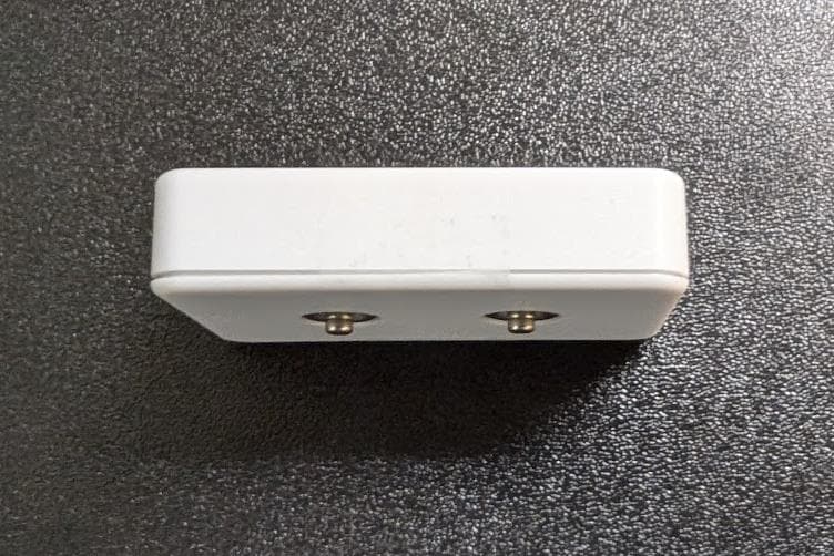
Click to zoom
Application Details
- Equipment Class
- DTS - Digital Transmission System
- Date of Grant
- Oct 10, 2024
- Application Purpose
- Original Equipment
- Date of Application
- Oct 09, 2024
- Equipment Note
- Wireless wetness sensor for senior care.
- Frequency Range
- 2402.00000000 - 2480.00000000
- Company
- Zealacare LLC
- Country
- United States
Documents & Files
Document Text
Text extracted from the exhibit documents filed with the FCC. Open a document above to read the original.
Users Manual
INSTRUCTIONSFORUSE SmartIncontinenceSystem This“InstructionsforUse”containsinformationonhowtousethe ZealacareSmartIncontinenceSystem TableofContents Contents GettingStarted.............................................................................................................................2 SettingUpTheZealacareApp...............................................................................................4 ZealacareAppFeatures............................................................................................................5 ZealacareSmartSensor..................................................................................................6 ZealacareComfortBriefs..........................................................................................................9 ZealacareInductiveCharger.........................................................................................11 WarrantyandReturnPolicy..........................................................................................13 TechnicalInformation....................................................................................................14 1 IFU-001Rev.A GettingStarted AbouttheZealacareSmartIncontinenceSystem TheZealacareSmartIncontinenceSystemisfocusedoncreatingcomfortandpeaceof mindforindividualswhoaresufferingfromurinaryincontinence.Ourpatentedsystem offersnotificationswhenaweteventhasoccurred,eliminatingtheguessworkandhelping lovedoneseliminatemanyofthenegativeside-effectsofurinaryincontinence.Weare strivingtoleadthemarketwithouruniqueproductswhileallowingfamilymembersand patientstoregainpurposeintheirlives. TheFDAregisteredZealacareSmartIncontinenceSystemconsistsof3differ ent components: 1.ZealacareComfortBriefs 2.ZealacareSmartSensorandInductiveCharger 3.ZealacareMobileApplication ZealacareComfortBriefs TheZealacareComfortBriefsarethefirstsmartbriefsoftheirkind.Whileoffering industry-leadingquality,ZealacareComfortBriefscontaintwosensorstripsthatrunthe lengthofthediaper.Thesestrips,whenconnectedtotheZealacareSmartSensor,are whatallowindividualsandcaretakersaliketoknowwhenaweteventhasoccurred. ZealacareSmartSensor TheZealacareSmartSensorisalowpowerdevicethatenablesindividualsandcaretakers toreceivereal-time,customizabledatasurroundingwetevents.UsingZealacare’s proprietarytechnology,thesensorhastheabilitytonotonlyrecognizewhenawetevent hasoccurred,buttheestimatedsaturationlevelofthediaperaftertheeventhastaken place.Thisallowsindividualssufferingfromincontinencetogainagreaterunderstandingof theirincontinenceneedswhileensuringthatcareisgivenwhenneeded. ZealacareApp TheZealacareAppisasimpleandeasy-to-useapplicationthatenablesindividualsand caregiverstotrackweteventsandcreateacustomizableexperience.Fromcustomizable notificationsbasedonestimatedsaturationlevels,toourstorefrontintegrateddirectlyinto 2 IFU-001Rev.A theapp,theZealacareAppoffersavarietyofpersonalizedfeaturesdesignedtoenhance theuserexperience. 3 IFU-001Rev.A SettingUpTheZealacareApp DownloadingandCreatinganAccount 1.DownloadtheZealacareAppfromtheGooglePlayStoreortheiOSAppleStore. 2.Followpromptstosignuporlogintotheapp. 3.Ifsigningupforthefirsttime,averificationcodewillbesenttoyouremail.After enteringthecode,youshouldreceiveamessagetellingyouthatyouraccounthas beenverified. 4.Youwillbebroughttoapagethatasksfor“AccountOwnerInformation”: 5.Enteryourfirstandlastnameintothemarkedboxes. 6.Acongratulationsscreenwillpopup.Proceedbyclickingthe“GetStarted”button. CreatingaHomeandAddingaCareRecipient 1.Enterahomenameandthecorrespondingzipcodeofthehomeofthecare recipient. 2.Enterrequiredinformationforthecarerecipient. 3.ProceedtolinkingtheSmartSensor.Ifyouhaveyettobuyasensor,visit www.zealacare.comtopurchasethesensor. 4.Referto“ConnectingmyZealacareSmartSensor”forinstructionsonhowto connectyoursensor. AddingAdditionalCaregivers 1.Ifsomeoneotherthantheaccountownerisprovidingcaretothecarerecipient,you mayinviteaguestcaregiverbyclickingthe“Addguestcaregiver”promptonthe homescreen. 2.Entertheemailoftheguestcaregiver. 3.AlinkwillbesenttothecaregiverallowingthemtodownloadtheZealacareApp andcreateanaccount. 4.Oncetheguestcaregivergoesthroughthesign-upprocess,theywillautomatically belinkedtotheaccountandwillbeabletobeginprovidingcare.Youmayneedto clickontheguestcaregiverprofiletoadjusttheirpermissionsettingsandgive accesstospecificcarerecipients. 5.Toaddadditionalcaregiversorcarerecipients,clickthe+iconfoundinthetopright cornerofthescreen. 4 IFU-001Rev.A ZealacareAppFeatures TheZealacareApphasmultiplefeaturestohelpprovideanenhancedandcustomizable levelofcare.Thesefeaturescanbetoggledonandoffinthenotificationwindowfoundon theapp.Thefeatureshighlightedinthisdocumentare: ●WetBriefNotification ●EstimatedSaturationLevelNotifications ●LowBatteryNotification ●SensorConnectionNotification ●NoBriefDetectedNotification WetBriefNotification Thisfeaturenotifiestheuserthatachangeissuggestedattheestimatedsaturationlevel forthebrief,assetbytheappuser.Thisfeaturecanbecustomizedbyslidingthebaruntil itresidesattheestimatedsaturationlevelthattheappuserwouldliketobenotifiedthata changeisneeded. EstimatedSaturationLevelNotification Thisfeatureallowsthecaregiverorusertoreceivenotificationsatvariousestimated saturationlevels,allowingthemtotracktheestimateddiapersaturationthroughmultiple stages. LowBatteryNotification NotifiestheuseroflowbatterylevelsoftheZealacareSmartSensor. SensorConnectionNotification Notifiestheuserwhenthesensorandtheapparenolongerconnected,resultinginthe inabilitytorecognizewetevents. NoBriefDetectedNotification Notifiestheuserwhentheappdetectsthatasensorhasnotbeenconnectedtoabrieffor acertainamountoftime. AccessingtheZealacareStorefrontDirectlyfromtheApp 5 IFU-001Rev.A TheZealacarestorefrontcanbeaccesseddirectlyfromtheapp.Thisallowsuserstoeasily placeneworderswithouttheneedtoberedirectedtoourstorefront.Userscanaccessthe storefrontbyclickingtheshopiconinthebottomleftcorneroftheapp. ZealacareSmartSensor PreparingforUse:ZealacareSmartSensor 1.Removet…
Text truncated - open the document above for the full version.
Attestation Statements
Federal Communications Commission Authorization and Evaluation Division 7435 Oakland Mills Road Columbia, MD 21046 USA Date: 09- 07- 2024 Ref: Attestation Statements Part 2.911(d)(7) Filing FCC ID: 2BF5N-SENS247 Zealacare (“the applicant”) certifies that, as of the date o f the filing o f the application, we designate ourselves as the U.S. agent for service of process. Designated U.S. Agent Information: FRN : 0035344373 Company Name: Zealacare 1. Address: 4262 W 4000 N, Cedar City , UT, 84721 Contact Pe rson: Aaron Collette Tel.: +1 (801) 376-2045 Email : [email protected] Sincerely, Aaron Collette Zealacare CEO
Attestation Statements
Federal Communications Commission Authorization and Evaluation Division 7435 Oakland Mills Road Columbia, MD 21046 USA Date: 09-07-2024 Ref: Attestation Statements Part 2.911(d)(5)(ii) Filing FCC ID: 2BF5N-SENS247 Aaron Collete, Zealacare CEO, (“the applicant”) certifies that, as of the date of the filing of the application, the applicant is not identified on the Covered List (as a specifically named entity, or any of its subsidiaries or affiliates) as an entity producing “covered” equipment. Sincerely, Aaron Collette Zealacare CEO
Attestation Statements
Federal Communications Commission Authorization and Evaluation Division 7435 Oakland Mills Road Columbia, MD 21046 USA Date: 09-07-2024 Ref: Attestation Statements Part 2.911(d)(5)(i) Filing FCC ID: 2BF5N-SENS247 Zealacare (“the applicant”) certifies that the equipment for which authorization is sought is not “covered” equipment prohibited from receiving an equipment authorization pursuant to section 2.903 of the FCC rules. Sincerely, Aaron Collette Zealacare CEO
Cover Letter(s)
09/07/2024 Federal Communications Commission 7435 Oakland Mills Road Columbia MD 21046 Subject: Request for Confidentiality FCC ID: 2BF5N-SENS247 To Whom It May Concern: Pursuant to the provisions of Sections 0.457 and 0.459 of the Commission’s rules (47 CFR §§ 0.457, 0.459), we are requesting the Commission to withhold the following attachments as confidential document from public disclosure indefinitely. Schematic Block Diagram Operational Description Above mentioned document contains detailed system and equipment description are considered as proprietary information in operation of the equipment. The public disclosure of above documents might be harmful to our company and would give competitor an unfair advantage in the market. Best Regards Aaron Collette CEO Zealacare
Cover Letter(s)
Authority to Act as Agent FCC 09/07/2024 Federal Communications Commission Authorization and Evaluation Division 7435 Oakland Mills Road Columbia, MD 21046 SUBJECT: FCC Application for FCC ID: 2BF5N-SENS247 To Whom It May Concern: We, the undersigned, hereby authorize Jason Stewart of VPI Technology at 313 W. 12800 S,. Suite 311, Draper UT 84020 to act as our agent and on our behalf, to apply to the Federal Communications Commission on our equipment. Any and all acts carried out by VPI Technology on our behalf shall have the same effect as acts of our own. This is to advise that we are in full compliance with the Anti- Drug Abuse Act. We, the applicant, are not subject to a denial of federal benefits pursuant to Section 5301 of the Anti-Drug Act of 1988, 21 USC853a, and no party to the application is subject to a denial of federal benefits pursuant to that section. Regards, Aaron Collette Zealacare CEO On behalf of Zealacare
External Photos
313 West 12800 South, Suite 311, Draper, UT 84020 • (801) 260-4040 SENS247_ExtPho.docx Page 1 of 6 PROPRIETARY External Photographs Photograph 1 – Top View of the EUT 313 West 12800 South, Suite 311, Draper, UT 84020 • (801) 260-4040 SENS247_ExtPho.docx Page 2 of 6 PROPRIETARY Photograph 2 – Bottom View of the EUT 313 West 12800 South, Suite 311, Draper, UT 84020 • (801) 260-4040 SENS247_ExtPho.docx Page 3 of 6 PROPRIETARY Photograph 3 – Side View of the EUT 313 West 12800 South, Suite 311, Draper, UT 84020 • (801) 260-4040 SENS247_ExtPho.docx Page 4 of 6 PROPRIETARY Photograph 4 – Side View of the EUT 313 West 12800 South, Suite 311, Draper, UT 84020 • (801) 260-4040 SENS247_ExtPho.docx Page 5 of 6 PROPRIETARY Photograph 5 – Front View of the EUT 313 West 12800 South, Suite 311, Draper, UT 84020 • (801) 260-4040 SENS247_ExtPho.docx Page 6 of 6 PROPRIETARY Photograph 6 – Back View of the EUT
Internal Photos
313 West 12800 South, Suite 311, Draper, UT 84020 • (801) 260-4040 SENS247_IntPho.docx Page 1 of 4 PROPRIETARY External Photographs Photograph 1 – Front View of the PCBA Chip Antenna WiFi Module 313 West 12800 South, Suite 311, Draper, UT 84020 • (801) 260-4040 SENS247_IntPho.docx Page 2 of 4 PROPRIETARY Photograph 2 – Back View of the PCBA 313 West 12800 South, Suite 311, Draper, UT 84020 • (801) 260-4040 SENS247_IntPho.docx Page 3 of 4 PROPRIETARY Photograph 3 – View of RF Circuitry 313 West 12800 South, Suite 311, Draper, UT 84020 • (801) 260-4040 SENS247_IntPho.docx Page 4 of 4 PROPRIETARY Photograph 4 – View of the PCB Mounting in the Enclosure
RF Exposure Info
313 West 12800 South, Suite 311, Draper, UT 84020 • (801) 260-4040 SENS247_MPE.docx Page 1 of 2 PROPRIETARY 47 C.F.R. Part 1, Subpart I, Section 1.1310 47 C.F.R. Part 2, Subpart J, Section 2.1091 Maximum Permissible Exposure Calculations For FCC ID: 2BF5N-SENS247 EUT Device Category = General Population/Uncontrolled Exposure MPE Summary: According subpart 1.1307 (b)(1) and 2.1091 systems operating under the provisions of this section shall be operated in a manner that ensures the public is not exposed to RF energy level in excess of the communication guidelines. Limits for General Population/Uncontrolled Exposure Limits for General Population/Uncontrolled Exposure Frequency Range (MHz) Electric Field Strength (V/m) Magnetic Field Strength (A/m) Power Density (mW/cm2) Averaging Time (Minutes) 0.3-1.34 614 1.63 *(100) 30 1.34-30 824/f 2.19/f *(180/f2) 30 30-300 27.5 0.073 0.2 30 300-1500 / / f/1500 30 1500-100,000 / / 1.0 30 f = frequency in MHz; * = Plane-wave equivalent power density Calculated Formulary: Predication of MPE limit at a given distance S = power density (in appropriate units, e.g. mW/cm 2 ) R = distance to the center of radiation of the antenna (appropriate units, e.g., cm) PG = EIRP 313 West 12800 South, Suite 311, Draper, UT 84020 • (801) 260-4040 SENS247_MPE.docx Page 2 of 2 PROPRIETARY MPE and Limit are calculated for this device as follows: BLE Transceiver Antenna Gain 2.00 dBi Freq Conducted Power (dBm) EIRP (dBm) EIRP (mW) Power Density at 20 cm (mW/cm 2 ) Limit (mW/cm 2 ) Margin (mW) 2402 -9.28 -7.28 0.187 0.00004 1.000 0.99996 2440 -10.50 -8.50 0.141 0.00003 1.000 0.99997 2480 -8.98 --6.98 0.200 0.00004 1.000 0.99996 WiFi Module, Antenna Gain 2.00 dBi Protocol Channel at Peak EIRP EIRP (dBm) EIRP (mW) Power Density at 20 cm (mW/cm 2 ) Limit (mW/cm 2 ) Margin (mW) 802.11b 2462 14.00 25.119 0.00500 1.00 0.99500 802.11g 2437 19.00 79.433 0.01580 1.00 0.98420 802.11n20 2462 18.00 63.096 0.01255 1.00 0.98745 802.11n40 2437 17.00 50.119 0.00997 1.00 0.99003 Multi Transmitter Ratio Evaluation: Worst Case BLE MPE Ratio = 0.00004 Worst Case Module MPE Ratio = 0.01580 0.00004 + 0.01580 = 0.01584 ≤ 1 Result: The device meets FCC MPE limit at 20 cm for General Population/Uncontrolled Exposure as specified in 47 CRF §1.1310 and §2.1091.
Test Report
313 West 12800 South, Suite 311 Draper, UT 84020 (801) 260-4040 Test Report Certification FCC ID 2BF5N-SENS247 Equipment Under Test SmartSensor Test Report Serial No V076289_01 Dates of Test May 14, July 29, and August 8, 2024 Report Issue Date September 30, 2024 Test Specifications: Applicant: FCC Part 15, Subpart C ZealaCare 4262 W 4000 N Cedar City, Utah 84721 U.S.A. 313 West 12800 South, Suite 311, Draper, UT 84020 • (801) 260-4040 V076289_01_Zealacare_SmartSensor_FCC_C.docx Page 2 of 41 PROPRIETARY Certification of Engineering Report This report has been prepared by VPI Technology, Inc. to document compliance of the device described below with the requirements of Federal Communications Commission (FCC) Part 15, Subpart C. This report may be reproduced in full. Partial reproduction of this report may only be made with the written consent of the laboratory. The results in this report apply only to the sample tested. Applicant Zealacare Manufacturer Zealacare Brand Name Zealacare Model Number SmartSensor FCC ID 2BF5N-SENS247 On this 30 th day of September 2024, I, individually and for VPI Technology, Inc., certify that the statements made in this engineering report are true, complete, and correct to the best of my knowledge, and are made in good faith. Although NVLAP has accredited the VPI Technology, Inc. EMC testing facilities, this report must not be used to claim product certification, approval, or endorsement by NVLAP, NIST, or any agency of the US government. VPI Technology, Inc. Emissions Tested by: Benjamin N. Antczak Reviewed by: Jason Stewart 313 West 12800 South, Suite 311, Draper, UT 84020 • (801) 260-4040 V076289_01_Zealacare_SmartSensor_FCC_C.docx Page 3 of 41 PROPRIETARY Revision History Revision Description Date 01 Original Report Release September 30, 2024 313 West 12800 South, Suite 311, Draper, UT 84020 • (801) 260-4040 V076289_01_Zealacare_SmartSensor_FCC_C.docx Page 4 of 41 PROPRIETARY Table of Contents 1 Client Information ................................................................................................................................. 5 1.1 Applicant ....................................................................................................................................... 5 1.2 Manufacturer ................................................................................................................................. 5 2 Equipment Under Test (EUT) ............................................................................................................... 6 2.1 Identification of EUT .................................................................................................................... 6 2.2 Customer Supplied Data (if applicable) ........................................................................................ 6 2.3 Description of EUT ....................................................................................................................... 6 2.4 EUT and Support Equipment ........................................................................................................ 7 2.5 Interface Ports on EUT ................................................................................................................. 7 2.6 Modification Incorporated/Special Accessories on EUT .............................................................. 7 2.7 Deviation from Test Standard ....................................................................................................... 7 3 Test Specification, Methods and Procedures ........................................................................................ 8 3.1 Test Specification .......................................................................................................................... 8 3.2 Methods & Procedures .................................................................................................................. 8 3.3 Test Procedure ............................................................................................................................ 12 4 Operation of EUT During Testing ...................................................................................................... 13 4.1 Operating Environment ............................................................................................................... 13 4.2 Operating Modes ......................................................................................................................... 13 4.3 EUT Exercise Software ............................................................................................................... 13 5 Summary of Test Results .................................................................................................................... 14 5.1 FCC Part 15, Subpart C .............................................................................................................. 14 5.2 Result .......................................................................................................................................... 14 6 Measurements, Examinations and Derived Results ............................................................................ 15 6.1 General Comments ...................................................................................................................... 15 6.2 Test Results ................................................................................................................................. 15 6.3 Sample Measurement Calculations ............................................................................................. 25 7 Test Procedures and Test Equipment .................................................................................................. 26 7.1 Conducted Emissions at Mains Ports .......................................................................................... 26 7.2 Direct Connection at the Antenna Port Tests .......................…
Text truncated - open the document above for the full version.
Test Report
Approval sheet Page 1 of 9 ASC_RFANT3216120A5T_V09 Aug. 2018 RFANT Series – RoHS Compliance MULTILAYER CERAMIC ANTENNA Halogens Free Product 2.4 GHz ISM Band RF Application P/N: RFANT3216120A5T *Contents in this sheet are subject to change without prior notice. Approval sheet Page 2 of 9 ASC_RFANT3216120A5T_V09 Aug. 2018 FEATURES 1. Surface Mounted Devices with a small dimension of 3.2 X 1.6 X1.2 mm 3 meet future miniaturization trend. 2. LTCC process 3. High stability in Temperature / Humidity Change APPLICATIONS 1. 2.4GHz ISM band RF applications 2. Bluetooth, Wireless, HomeRF CONSTRUCTION DIMENSIONS Figure Symbol Dimension (mm) L 3.20 ± 0.20 W 1.60 ± 0.10 T 1.20 ± 0.10 A 0.25 ± 0.15 PINConnection 1 Feeding 2 Identification Mark 3 Soldering terminal Approval sheet Page 3 of 9 ASC_RFANT3216120A5T_V09 Aug. 2018 ELECTRICAL CHARACTERISTICS RFANT3216120A5T Specification Working Frequency Range 2450 ± 50 MHz Fc (GHz) 2.9 Gain (dBi) 2 (Typical) VSWR 2 max. Series 1 6.8nH Matching component value Series 2 - Power Capacity 3 W max. Maximum Input Power 5 Watts for 5 minutes Operation Temperature -40 ̊C ~ +85 ̊C Polarization Linear Azimuth Beamwidth Omni-directional * This frequency must be adjusted to 2.45GHz with matching circuit. SOLDER LAND PATTERN DESIGN Figure Approval sheet Page 4 of 9 ASC_RFANT3216120A5T_V09 Aug. 2018 Antenna on Test Board ( Thickness 1.2mm) Antenna S11 on Test Board Antenna VSWR on Test Board Approval sheet Page 5 of 9 ASC_RFANT3216120A5T_V09 Aug. 2018 RADIATION PATTERN Radiation Pattern and Gain were dependent on measurement board design. The specification of RFANT3216120A5T antenna was measured based on the PCB size and installation position as shown in the below figure Test Board Vertical Horizontal Y - Z Plane Average Gain= 0.948 dBi X Cut -40 -30 -20 -10 0 0 30 60 90 120 150 180 210 240 270 300 330 Peak Gain = 2.93dBi Average Gain = 0.60dBi X Cut -40 -30 -20 -10 0 0 30 60 90 120 150 180 210 240 270 300 330 Peak Gain= -5.60dBi Average Gain=-10.19dBi X - Z Plane Average Gain= -2.147 dBi X Cut -40 -30 -20 -10 0 0 30 60 90 120 150 180 210 240 270 300 330 127.0 Peak Gain= -4.98 dBi Average Gain= -9.68dBi X Cut -40 -30 -20 -10 0 0 30 60 90 120 150 180 210 240 270 300 330 Peak Gain= 1.61 dBi Average Gain= -2.99 dBi X - Y Plane Average Gain= -2.810 dBi X Cut -40 -30 -20 -10 0 0 30 60 90 120 150 180 210 240 270 300 330 Peak Gain= -3.79 dBi Average Gain= -8.89dBi X Cut -40 -30 -20 -10 0 0 30 60 90 120 150 180 210 240 270 300 330 Peak Gain= 0.77 dBi Average Gain= -4.04 dBi x Y Z x Y x Y Z X Z X Z Y Z Y Approval sheet Page 6 of 9 ASC_RFANT3216120A5T_V09 Aug. 2018 RELIABILITY TEST Test item Test condition / Test method Specification Solderability JIS C 0050-4.6 JESD22-B102D *Solder bath temperature:235 5C *Immersion time:2 0.5 sec Solder:Sn3Ag0.5Cu for lead-free At least 95% of a surface of each terminal electrode must be covered by fresh solder. Leaching (Resistance to dissolution of metallization) IEC 60068-2-58 *Solder bath temperature:260 5C *Leaching immersion time:30 0.5 sec Solder : SN63A Loss of metallization on the edges of each electrode shall not exceed 25%. Resistance to soldering heat JIS C 0050-5.4 *Preheating temperature:120~150°C, 1 minute. *Solder temperature:2705C *Immersion time:101 sec Solder:Sn3Ag0.5Cu for lead-free Measurement to be made after keeping at room temperature for 242 hrs No mechanical damage. Electrical specification shall satisfy the descriptions in electrical characteristics under the operational temperature range within -40 ~ 85°C. Loss of metallization on the edges of each electrode shall not exceed 25%. Drop Test JIS C 0044 Customer’s specification. *Height:75 cm *Test Surface:Rigid surface of concrete or steel. *Times:6 surfaces for each units;2 times for each side. No mechanical damage. Electrical specification shall satisfy the descriptions in electrical characteristics under the operational temperature range within -40 ~ 85°C. Vibration JIS C 0040 *Frequency:10Hz~55Hz~10Hz(1min) *Total amplitude:1.5mm *Test times:6hrs.(Two hrs each in three mutually perpendicular directions) No mechanical damage. Electrical specification shall satisfy the descriptions in electrical characteristics under the operational temperature range within -40 ~ 85°C. Adhesive Strength of Termination JIS C 0051- 7.4.3 *Pressurizing force: 5N(≦0603);10N(>0603) *Test time:10±1 sec No remarkable damage or removal of the termination. Bending test JIS C 0051- 7.4.1 The middle part of substrate shall be pressurized by means of the pressurizing rod at a rate of about 1 mm/s per second until the deflection becomes 1mm/s and then pressure shall be maintained for 51 sec. Measurement to be made after keeping at room temperature for 242 hours No mechanical damage. Electrical specification shall satisfy the descriptions in electrical characteristics under the operational temperature range within -40 ~ 85°C. Approval sheet Page 7 of 9 ASC_RFANT3216120A5T_V09 Aug. 2018 Temperature cycle JIS C 0025 1. 303 minutes at -40C3C, 2. 10~15 minutes at room temperature, 3. 303 minutes at +85C3C, 4. 10~15 minutes at room temperature, Total 100 continuous cycles Measurement to be made after keeping at room temperature for 242 hrs No mechanical damage. Electrical specification shall satisfy the descriptions in electrical characteristics under the operational temperature range within -40 ~ 85°C. High temperature JIS C 0021 *Temperature:85C2C *Test duration:1000+24/-0 hours Measurement to be made after keeping at room temperature for 242 hrs No mechanical damage. Electrical specification shall satisfy the descriptions in electrical characteristics under the operational temperature range within -40 ~ 85°C. Humidity (steady conditions) JIS C 0022 *Humidity:90% to 95% R.H. *Temperature:402C *Time:1000+24/-0 hrs. Measurement to be made after keeping at room temperature for 242 hrs ※ 500hrs measuring the first data then 1000hrs data No mechanical damage. Electrical spe…
Text truncated - open the document above for the full version.
Test Setup Photos
313 West 12800 South, Suite 311, Draper, UT 84020 • (801) 260-4040 SENS247_Tsup.docx Page 1 of 5 PROPRIETARY Test Set Up Photographs Radiated Photograph 1: Front View Radiated Emissions Worst Case – Above 1000 MHz Configuration Photograph 2: Back View Radiated Emissions Worst Case – Above 1000 MHz Configuration 313 West 12800 South, Suite 311, Draper, UT 84020 • (801) 260-4040 SENS247_Tsup.docx Page 2 of 5 PROPRIETARY Photograph 3: Edge Placement Worst Case Photograph 4: Flat Placement 313 West 12800 South, Suite 311, Draper, UT 84020 • (801) 260-4040 SENS247_Tsup.docx Page 3 of 5 PROPRIETARY Photograph 9: Vertical Placement 313 West 12800 South, Suite 311, Draper, UT 84020 • (801) 260-4040 SENS247_Tsup.docx Page 4 of 5 PROPRIETARY Reference Test Set Up Photographs Photograph 10: Reference Photo of Test Setup for Emissions Below 30 MHz Photograph 11: Reference Photo of Test Setup for Emissions From 30 MHz to 1000 MHz 313 West 12800 South, Suite 311, Draper, UT 84020 • (801) 260-4040 SENS247_Tsup.docx Page 5 of 5 PROPRIETARY Photograph 12: Reference Photo of Test Setup for Emissions Above 1000 MHz
Contact Information
Applicant
Aaron Collette(CEO)
Test Firm
VPI TechnologyJason Stewart
[email protected]801-495-2310
Technical Specifications
| # | Rule Parts | Frequency Range | Power Output |
|---|---|---|---|
| 1 | 15C | 2.40 GHz - 2.48 GHz | 130.00 µW |