2BF8C-SE30BTAmplifier
EBS Sweden AB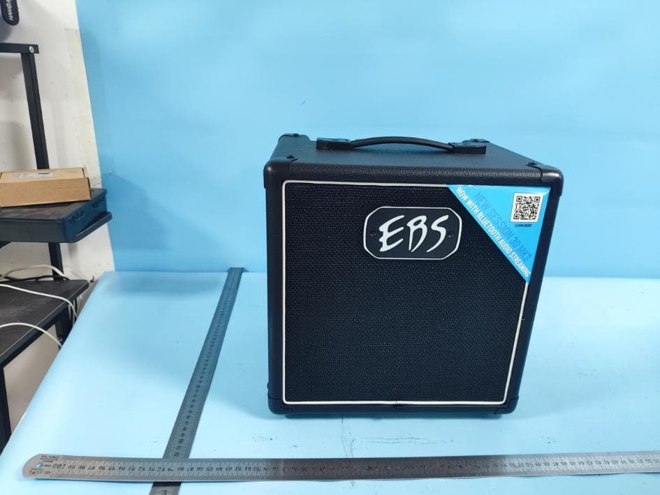
Click to zoom
Application Details
- Equipment Class
- DTS - Digital Transmission System
- Date of Grant
- May 09, 2024
- Application Purpose
- Original Equipment
- Date of Application
- May 09, 2024
- Equipment Note
- Amplifier
- Frequency Range
- 2402.00000000 - 2480.00000000
- Company
- EBS Sweden AB
- Country
- Sweden
Documents & Files
Document Text
Text extracted from the exhibit documents filed with the FCC. Open a document above to read the original.
Users Manual
USERS MANUAL EBS SESSION 30 MK3 www.ebssweden.comwww.ebssweden.com Session 30 Mk3 COMPACT BASS COMBO USERS MANUAL EBS SESSION 30 MK3 www.ebssweden.comwww.ebssweden.com About the EBS Session 30 Mk3! The Session combo Mk3 is an excellent tool to help you grow as a bass player. The honest and natural sound reveals the things you need to work on. It also rewards progress as you grow your skills. The Session 30 Mk3 combo is equipped with an 8” speaker and a tweeter. It features Bluetooth audio streaming and a headphone output that makes it perfect for practice. The recording XLR-output is useful to connect to a mixing console or recording interface. The Session 30 Mk3 is designed and developed in the heart of Sweden by EBS. GETTING STARTED... 1. Carefully unpack the bass combo. 2. Check that the Volume and Gain controls are set to zero, fully counter clockwise. Set the two filter controls to mid position. Now the EBS Session30s’ settings are ”zeroed” and ready to be personalized. 3. Power up the combo and plug in your bass. 4. While plucking the strings as hard as you would during your hardest playing, adjust the GAIN knob until the PEAK led starts to flash only at highest peaks. 5. Move over to the VOLUME knob and adjust for the desired output volume. BUILDING THE SOUND... Your EBS Session 30 Mk3 features a tone shaping circuit that will enable you to create a variety of bass sounds. 6. The filters are basically the boost/cut design. This means that the level controls marked with + and - signs, either boost or cuts the selected frequency band. 7. Gradually increase or decrease the level and vary the frequency of the various filter sections. Notice how the sound is affected. 8. If you have a smartphone or other sound source that can send audio over Bluetooth, you may pair the device with your Session 30 Mk3. To do so, make sure Bluetooth is activated on your device, push and hold the button next to the Bluetooth symbol on the Session combo until the lamp flickers fast and steady. Then go to your device, and look for ’EBS Session’ to show up on the list where you connect to other devices via Bluetooth. Select the ’EBS Session’ and wait until it says ’Connected’. Note that the volume must be controlled from the source here, since this input has no associated level control. This was a brief tutorial of EBS Session 30 Mk3. As you go on further in this manual, you will learn how to use and utilize all of the features that the EBS Session 30 Mk3 offers you. USERS MANUAL EBS SESSION 30 MK3 www.ebssweden.comwww.ebssweden.com EBS SESSION 30 Mk3 – BLOCK DIAGRAM USERS MANUAL EBS SESSION 30 MK3 www.ebssweden.comwww.ebssweden.com EBS SESSION 30 Mk3 – CONTROLS 1. INPU T -A low noise, high impedance instrument input that will interface with passive and active instruments perfectly. 2. GAIN -Control to adjust the instruments’ signal strength to the right operating level. For optimum basic signal level, turn up the GAIN knob until the PEAK led starts flashing from the strongest signal from the instrument. Note: A correctly set GAIN is vital for the signal processing to work properly in the EBS Session 30 Mk3. 3. BASS - is a ’shelving’ type filter with a wide gain range. 4. TREBLE - is a ’shelving’ type filter controlling the higher mids and treble registers, giving presence and ambiance to the sound. 1 257 6 34 8 5. VOLUME -The VOLUME knob controls all volume in the unit, controlling the poweramp/speaker and headphones output. The balanced output (XLR) is not effected by the setting of this knob. USERS MANUAL EBS SESSION 30 MK3 www.ebssweden.comwww.ebssweden.com 6. BLUETOOTH PAIRING -Push down and hold this button until the blue light flickers steady and fast. Then go to the device that you would like to pair, activate Bluetooth and find ’EBS Session’ on the list of discovered units and select it. Once connected a bleep sound will be audible through the Session combo and the lamp will give a steady blue light indicating the pairing is successful. Now you can stream audio from your device through the speaker or headphones of the Session Mk3. Note that you need to adjust the volume level for the streamed audio on the external device, and that the speaker will play the sound in mono, while the headphones output will provide stereo sound. 7. HEADPHONES – Connect your favorite headphones here. By connecting the headphones the speakers will automatically be muted. 8. BALANCED OUTPUT - Is a high quality balanced output that functions as a line box for connecting to PA mixing consoles or to studio or broadcast recording units. Lifting ground is a great aid in many occasions. When required, set the Gnd Lift switch to inner position to disconnect the ground from the output. The Bluetooth streamed audio is not present at this output. 9. POWER – Powers the unit on or off. The switch is located on the back of the combo. USERS MANUAL EBS SESSION 30 MK3 www.ebssweden.comwww.ebssweden.com POWERAMP - The internal poweramp is of highly integrated design giving natural sound reproduction and output with exceptional clarity. The incorporated soft clip system provides tube-alike distortion characteristics, protects the power amp from saturation and increases its output performance and sound quality. CABINET - The cabinet is equipped with one specially designed fullrange 8" speaker and a tweeter. In addition, the cabinet is carefully tuned for best bass response. FCC Statement: This device complies with part 15 of the FCC Rules. Operation is subject to the following two conditions: (1) This device may not cause harmful interference, and (2) this device must accept any interference received, including interference that may cause undesired operation. This equipment has been tested and found to comply with the limits for a Class B digital device, pursuant to part 15 of the FCC Rules. These limits are designed to provide reasonable protection against harmful interference in a residential installation. This Equipment generates,uses and…
Text truncated - open the document above for the full version.
Attestation Statements
EBS Sweden AB (2024.05.06) Eurofins Electrical and Electronic Testing NA, Inc. 914 West Patapsco Avenue Baltimore, MD 21230 RE: Attestation Statements Part 2.911(d)(5)(i) request for (FCC ID: 2BF8C‐SE30BT) [EBS Sweden AB ] (“the applicant”) certifies that the equipment for which authorization is sought is not “covered” equipment prohibited from receiving an equipment authorization pursuant to section 2.903 of the FCC rules. Sincerely, (Applicant signature) (Applicant printed name) Mats Kristoffersson EBS Sweden AB (2024.05.06) Eurofins Electrical and Electronic Testing NA, Inc. 914 West Patapsco Avenue Baltimore, MD 21230 RE: Attestation Statements Part 2.911(d)(5)(ii) request for (FCC ID: 2BF8C‐SE30BT) [EBS Sweden AB ] (“the applicant”) certifies that, as of the date of the filing of the application, the applicant is not identified on the Covered List as an entity producing “covered” equipment. Sincerely, (Applicant signature) (Applicant printed name) Mats Kristoffersson
Cover Letter(s)
EBS Sweden AB Agent Authorization Letter 2024-05-06 Eurofins Electrical and Electronic Testing NA, Inc. 914 West Patapsco Avenue Baltimore, MD 21230 USA RE: LETTER OF AGENT AUTHORIZATION To Whom It May Concern: We, the undersigned, hereby authorize Shenzhen Most Technology Service Co., Ltd. to act on our behalf in all matters relating to application for equipment authorization, including the signing of all documents relating to these matters. We also hereby certify that no party to the application authorized hereunder is subject to the denial of benefits, including FCC benefits, pursuant to Section 5301 of the Anti-Drug Abuse Act of 1988, 21 U.S.C.853(a). This agreement expires one year from the current date. Sincerely, Name: Mats Kristoffersson Position: Technical Director Company Name: EBS Sweden AB Address: Grindstuvagen 44-46,SE-167,33 Bromma,Sweden Tel / Fax 850121101/N/A E-Mail: [email protected]
Cover Letter(s)
EBS Sweden AB Long Term Confidentiality Request Letter 2024-05-06 Eurofins Electrical and Electronic Testing NA, Inc. 914 West Patapsco Avenue Baltimore, MD 21230 USA RE: CONFIDENTIALITY REQUEST FOR (FCC ID: 2BF8C-SE30BT) To Whom It May Concern: This letter serves as an official request for confidentiality under sections 0.457 and 0.459 of CFR 47. We have requested that the - e.g. Block diagram - e.g. SCH - e.g. Operational Description required to be submitted with this application be permanently withheld from public review. The above documents are company proprietary information that could never get into the possession of your competition. Please contact me if there is any information you may need. Sincerely, Name: Mats Kristoffersson Position: Technical Director Company Name: EBS Sweden AB Address: Grindstuvagen 44-46,SE-167,33 Bromma,Sweden Tel / Fax 850121101/N/A E-Mail: [email protected]
External Photos
ModelNo.:SE30BT FRONTVIEWOFSAMPLE BACKVIEWOFSAMPLE ModelNo.:SE30BT LEFTVIEWOFSAMPLE RIGHTVIEWOFSAMPLE ModelNo.:SE30BT TOPVIEWOFSAMPLE BOTTOMVIEWOFSAMPLE ModelNo.:SE30BT
ID Label/Location Info
Label size:60mm*20mm Product name: Amplifier Product model: SE30BT FCC ID: 2BF8C‐SE30BT Label location
Internal Photos
ModelNo.:SE30BT Page1of4 INTERNALPHOTOOFSAMPLE INTERNALPHOTOOFSAMPLE ModelNo.:SE30BT Page2of4 INTERNALPHOTOOFSAMPLEPCB INTERNALPHOTOOFSAMPLEPCB ANT Location ModelNo.:SE30BT Page3of4 INTERNALPHOTOOFSAMPLEPCB INTERNALPHOTOOFSAMPLEPCB ModelNo.:SE30BT Page4of4 INTERNALPHOTOOFSAMPLEPCB INTERNALPHOTOOFSAMPLEPCB
RF Exposure Info
ShenzhenMostTechnologyServiceCo.,Ltd. EastA,1floorofNewAolinFactorybuiding,LangshanErlu,NorthDistrict, Hi-techIndustryPark,Nanshan,Shenzhen,Guangdong,China RFExposureEvaluationReport ReportReferenceNo. ....................... : FCCID.. ............................................... : MTEB24040369-H 2BF8C-SE30BT Compiledby (position+printedname+signature)..:FileadministratorsAlisaLuo Supervisedby (position+printedname+signature) .. :TestEngineerSunnyDeng Approvedby (position+printedname+signature) .. : ManagerYvetteZhou Dateofissue ......................................... :April.29,2024 RepresentativeLaboratoryName . :ShenzhenMostTechnologyServiceCo.,Ltd. Address.................................................: No.5,2ndLangshanRoad,NorthDistrict,Hi-techIndustrialPark, Nanshan,Shenzhen,Guangdong,China. Applicant’sname...............................: EBSSwedenAB Address.................................................: Grindstuvagen44-46,SE-167,33Bromma,SWEDEN Testspecification/Standard............: 47CFRPart1.1307;47CFRPart1.1310 KDB447498D01GeneralRFExposureGuidancev06 TRFOriginator......................................:ShenzhenMostTechnologyServiceCo.,Ltd. ShenzhenMostTechnologyServiceCo.,Ltd.Allrightsreserved. Thispublicationmaybereproducedinwholeorinpartfornon-commercialpurposesaslongasthe ShenzhenMostTechnologyServiceCo.,Ltd.isacknowledgedascopyrightownerandsourceofthe material.ShenzhenMostTechnologyServiceCo.,Ltd.takesnoresponsibilityforandwillnotassume liabilityfordamagesresultingfromthereader'sinterpretationofthereproducedmaterialduetoits placementandcontext. Testitemdescription........................: Amplifier TradeMark............................................: EBS Model/Typereference.........................: SE30BT ListedModels......................................:N/A ModulationType .................................. :GFSK,π/4DQPSK,8DPSK OperationFrequency .......................... :From2402MHzto2480MHz HardwareVersion.................................V1.3 SoftwareVersion...................................9BFB81BF_31180BDC Rating.....................................................:AC120V/60Hz Result.....................................................:PASS ReportNo.:MTEB24040369-HPage 2 of 6 TESTREPORT EquipmentunderTest:Amplifier Model/Type:SE30BT ListedModels:N/A RemarkN/A Applicant:EBSSwedenAB Address:Grindstuvagen44-46,SE-167,33Bromma,SWEDEN Manufacturer:HUIZHOUMINGSELECTRONICPRODUCTCO.,LIMITED Address :Baiyunkeng,Tuhu,Danshui,Huiyang,Huizhou,Guangdong,China, 516211 TestResult:PASS Thetestreportmerelycorrespondstothetestsample. Itisnotpermittedtocopyextractsofthesetestresultwithoutthewrittenpermissionofthetest laboratory. ReportNo.:MTEB24040369-HPage 3 of 6 1.RevisionHistory RevisionIssueDateRevisionsRevisedBy 00 2024.04.29 InitialIssueAlisaLuo ReportNo.:MTEB24040369-HPage 4 of 6 2.SAREvaluation 2.1RFExposureComplianceRequirement 2.1.1StandardRequirement AccordingtoKDB447498D01GeneralRFExposureGuidancev06 4.3.1.StandaloneSARtestexclusionconsiderations UnlessspecificallyrequiredbythepublishedRFexposureKDBprocedures,standalone1-gheador bodyand10-gextremitySARevaluationforgeneralpopulationexposureconditions,bymeasurementor numericalsimulation,isnotrequiredwhenthecorrespondingSARExclusionThresholdcondition,listed below,issatisfied. 2.1.2Limits AccordingtoFCCPart1.1310:Thecriterialistedinthefollowingtableshallbeusedtoevaluatethe environmentimpactofhumanexposuretoradiofrequency(RF)radiationasspecifiedinpart1.1307(b) F=FrequencyinMHz FriisFormula Friistransmissionformula:Pd=(Pout*G)/(4*Pi*R 2 )Where Pd=powerdensityinmW/cm2 Pout=outputpowertoantennainmW G=gainofantennainlinearscale Pi=3.1416 R=distancebetweenobservationpointandcenteroftheradiatorincm PdidthelimitofMPE,1mW/cm2.Ifweknowthemaximumgainoftheantennaandthetotalpower inputtotheantenna,throughthecalculation,wewillknowthedistancerwheretheMPElimitisreached. ReportNo.:MTEB24040369-HPage 5 of 6 2.1.3EUTRFExposure BLE GFSK Testchannel PeakOutputPower (dBm) Tuneuptolerance (dBm) Maximumtune-upPower (dBm) Lowest(2402MHz)1.9301.930±12.930 Middle(2440MHz)0.1150.115±11.115 Highest(2480MHz)-0.608-0.608±10.392 BLE Worstcase:GFSK Channel Maximum tune-up Power (dBm) Maximumtune-up Power (MW) AntennaGain (dBi) Power Density atR=20 cm (mW/cm2) LimitResult Lowest(2402MHz)2.9301.965.30.00131.0Pass Note:1)RefertoreportMTEB24040369-R1forEUTtestMaxConductedaverageOutputPowervalue. Note:2)Pd=(Pout*G)/(4*Pi*R 2 )=(1.96*3.39)/(4*3.1416*20 2 )=0.0013 Note:3)EUT'sBluetoothmoduleismorethan20cmawayfromthehumanbody. ReportNo.:MTEB24040369-HPage 6 of 6 BTclassic GFSK Testchannel PeakOutputPower (dBm) Tuneuptolerance (dBm) Maximumtune-upPower (dBm) Lowest(2402MHz)2.0522.052±13.052 Middle(2441MHz)0.2160.216±11.216 Highest(2480MHz)-0.494-0.494±10.506 π/4DQPSK Testchannel PeakOutputPower (dBm) Tuneuptolerance (dBm) Maximumtune-upPower (dBm) Lowest(2402MHz)4.5294.529±15.529 Middle(2441MHz)2.5592.559±13.559 Highest(2480MHz)1.8721.872±12.872 8DPSK Testchannel PeakOutputPower (dBm) Tuneuptolerance (dBm) Maximumtune-upPower (dBm) Lowest(2402MHz)5.0315.031±16.031 Middle(2441MHz)3.0803.080±14.080 Highest(2480MHz)2.3782.378±13.378 Worstcase:8DPSK Channel Maximum tune-upPower (dBm) Maximumtune-up Power (MW) AntennaGain(dBi) Power Density atR=20 cm (mW/cm2) LimitResult Lowest(2402MHz)6.0314.0095.30.00271.0Pass Note:1)RefertoreportMTEB24040369-R2forEUTtestMaxConductedaverageOutputPowervalue. Note:2)Pd=(Pout*G)/(4*Pi*R2)=(4.009*3.39)/(4*3.1416*20 2 )=0.0027 Note:3)EUT'sBluetoothmoduleismorethan20cmawayfromthehumanbody. .......................THEENDOFREPORT.........................
Test Report
ShenzhenMostTechnologyServiceCo.,Ltd. No.5,2ndLangshanRoad,NorthDistrict,Hi-techIndustrialPark,Nanshan, Shenzhen,Guangdong,China. TESTREPORT FCCRulesPart15.247 ReportReferenceNo........................: FCCID................................................: MTEB24040369-R1 2BF8C-SE30BT Compiledby (position+printedname+signature)..:FileadministratorsAlisaLuo Supervisedby (position+printedname+signature)..:TestEngineerSunnyDeng Approvedby (position+printedname+signature)..: ManagerYvetteZhou Dateofissue.........................................:April.24,2024 RepresentativeLaboratoryName.:ShenzhenMostTechnologyServiceCo.,Ltd. Address ................................................. : No.5,2ndLangshanRoad,NorthDistrict,Hi-techIndustrialPark, Nanshan,Shenzhen,Guangdong,China. Applicant’sname...............................: EBSSwedenAB Address.................................................: Grindstuvagen44-46,SE-167,33Bromma,SWEDEN Testspecification/Standard............: FCCRulesPart15.247 TRFOriginator......................................:ShenzhenMostTechnologyServiceCo.,Ltd. ShenzhenMostTechnologyServiceCo.,Ltd.Allrightsreserved. Thispublicationmaybereproducedinwholeorinpartfornon-commercialpurposesaslongasthe ShenzhenMostTechnologyServiceCo.,Ltd.isacknowledgedascopyrightownerandsourceofthe material.ShenzhenMostTechnologyServiceCo.,Ltd.takesnoresponsibilityforandwillnotassume liabilityfordamagesresultingfromthereader'sinterpretationofthereproducedmaterialduetoits placementandcontext. Testitemdescription........................: Amplifier TradeMark...........................: EBS Model/Typereference.........................: SE30BT ListedModels.....................................:N/A ModulationType .................................. :GFSK OperationFrequency .......................... :From2402MHzto2480MHz HardwareVersion.................................V1.3 SoftwareVersion................................... 9BFB81BF_31180BDC Rating ..................................................... :AC120V/60Hz Result ..................................................... :PASS ReportNo.:MTEB24040369-R1Page 2 of 38 TESTREPORT EquipmentunderTest:Amplifier Model/Type:SE30BT ListedModels:N/A RemarkN/A Applicant:EBSSwedenAB Address: Grindstuvagen44-46,SE-167,33Bromma,SWEDEN Manufacturer:HUIZHOUMINGSELECTRONICPRODUCTCO.,LIMITED Address : Baiyunkeng,Tuhu,Danshui,Huiyang,Huizhou,Guangdong,China, 516211 TestResult : PASS Thetestreportmerelycorrespondstothetestsample. Itisnotpermittedtocopyextractsofthesetestresultwithoutthewrittenpermissionofthetest laboratory. ReportNo.:MTEB24040369-R1Page 3 of 38 Contents 1.REVISIONHISTORY.........................................................................................................................4 2.TESTSTANDARDS............................................................................................................................5 3.SUMMARY...............................................................................................................................................6 3.1.GeneralRemarks.........................................................................................................................................6 3.2.ProductDescription....................................................................................................................................6 3.3.EquipmentUnderTest................................................................................................................................6 3.4.ShortdescriptionoftheEquipmentunderTest(EUT)............................................................................6 3.5.EUToperationmode....................................................................................................................................7 3.6.BlockDiagramofTestSetup......................................................................................................................7 3.7.TestItem(EquipmentUnderTest)Description*.......................................................................................7 3.8.AuxiliaryEquipment(AE)Description.......................................................................................................7 3.9.AntennaInformation....................................................................................................................................8 3.10.EUTconfiguration......................................................................................................................................8 3.11.Modifications..............................................................................................................................................8 4.TESTENVIRONMENT.......................................................................................................................9 4.1.Addressofthetestlaboratory...................................................................................................................9 4.2.Environmentalconditions...........................................................................................................................9 4.3.TestDescription.........................................................................................................................................10 4.4.Statementofthemeasurementuncertainty...........................................................................................10 4.5.EquipmentsUsedduringtheTest...........................................................................................................11 5.TESTCONDITIONSANDRESULTS.....................................................................................12 5.1.ACPowerConductedEmission...............................................................................................................12 5.2.RadiatedEmission.....................................................................................................................................15 5.3.Maxim…
Text truncated - open the document above for the full version.
Test Report
Application Note AN043 Small Size 2.4 GHz PCB antenna By Audun Andersen 1 KEYWORDS • CC25xx • CC24xx • CC2480 • PCB antenna • USB dongle • 2.4 GHz • Inverted F Antenna 2 INTRODUCTION The PCB antenna used on the CC2511 USB dongle reference design is described in this application note. Even if the antenna presented is for a USB dongle design it can be used in all 2.4 GHz designs, especially where small space is required for the antenna. This application note describes the antenna dimensions, the RF performance and considerations for complying with regulatory limits when using this design. The suggested antenna design requires no more than 15.2 x 5.7 mm of space and ensures a VSWR ratio of less than 2 across the 2.4 GHz ISM band when connected to a 50 ohm source. Figure 1: CC2511 USB Dongle SWRA117D Page 1 of 21 Application Note AN043 Table of Contents 1 KEYWORDS...................................................................................................................1 2 INTRODUCTION.............................................................................................................1 3 ABBREVIATIONS...........................................................................................................2 4 ANTENNA DESIGN........................................................................................................3 4.1 DESIGN GOALS..........................................................................................................3 4.2 SIMULATION...............................................................................................................3 4.3 LAYOUT AND IMPLEMENTATION...................................................................................4 5 TEST RESULTS.............................................................................................................5 5.1 REFLECTION..............................................................................................................5 5.2 RADIATION PATTERN..................................................................................................7 5.3 OUTPUT POWER......................................................................................................15 5.4 SPURIOUS EMISSION AND HARMONICS......................................................................17 6 CONCLUSION ..............................................................................................................20 7 GENERAL INFORMATION..........................................................................................21 7.1 DOCUMENT HISTORY................................................................................................21 3 ABBREVIATIONS CAD Computer Aided Design CC24xx CC2400, CC2420, CC2430 and CC2431 CC25xx CC2500, CC2510, CC2511, CC2550 and CC2520 CC2480 Z-Accel ZigBee Processor IFA Inverted F Antenna ISM Industrial, Scientific and Medical LOS Line Of Sight PCB Printed Circuit Board PER Packet Error Rate VSWR Voltage Standing Wave Ratio SWRA117D Page 2 of 21 Application Note AN043 4 ANTENNA DESIGN The PCB antenna on the CC2511 USB dongle reference design is a meandered Inverted F Antenna (IFA). The IFA was designed to match an impedance of 50 ohm at 2.45 GHz. Thus no additional matching components are necessary. 4.1 Design Goals The reflection at the feed point of the antenna determines how much of the applied power is delivered to the antenna. A reflection of less than -10 dB across the 2.4 GHz ISM band, when connected to a 50 ohm source, was a design goal. Reflection of less than -10 dB, or VSWR less than 2, ensures that more than 90% of the available power is delivered to the antenna. Bandwidth is in this document defined as the frequency band where more than 90% of the available power is delivered to the antenna. Another design goal was to fit the size of the PCB antenna on a USB dongle and to obtain good performance also when the dongle is connected to a computer. 4.2 Simulation IE3D from Zeland, which is an electromagnetic simulation tool, was used to design the antenna. The accuracy of the simulation is controlled by the mesh. An increase of the mesh increases the simulation time. Thus, for initial simulations mesh = 1 should be used. When a fairly good result is achieved a higher mesh should be used to obtain more accurate results. Comparison of simulation and measurement results shows that the measured reflection is between the result obtained with mesh = 5 and mesh = 1; see Figure 2 for details. Figure 2: Comparison of Simulation and Measurements Results SWRA117D Page 3 of 21 Application Note AN043 4.3 Layout and Implementation Small changes of the antenna dimensions may have large impact on the performance. Therefore it is strongly recommended to make an exact copy of the reference design to achieve optimum performance. The easiest way to implement the antenna is to import the gerber or DXF file showing the antenna layout. These files are named IFA_USB.spl and IFA_USB.dxf respectively and are included in the CC2511 USB dongle reference design available from http://www.ti.com\lpw. The imported file can be used as a template when drawing the antenna. By using this procedure it should be possible to make an exact copy. If the PCB CAD tool being used does not support import of DXF or gerber files, Figure 3 and Table 1 should be used to ensure correct implementation. It is recommended to generate a gerber file for comparison with IFA_USB.spl when making a manual implementation. Most gerber viewers have the possibility to import several gerber files at the same time. Thus by placing the gerber file, showing the manually implemented antenna, on top of IFA_USB.spl it is easy to verify that the antenna is correctly implemented. It is also recommended to use the same thickness and type of PCB material as used in the reference design. Information about the PCB can be found in a separate readme file included in the reference design. To compensate for a thicker/thinner P…
Text truncated - open the document above for the full version.
Test Setup Photos
ModelNo.:SE30BT CETESTSETUP RETESTSETUP ModelNo.:SE30BT RETESTSETUP v
Contact Information
Applicant
Mats Kristoffersson(Technical Director)
Test Firm
Shenzhen Most Technology Service Co., Ltd.Sunny Deng
[email protected]0755-26980487
Technical Specifications
| # | Rule Parts | Frequency Range | Power Output |
|---|---|---|---|
| 1 | 15C | 2.40 GHz - 2.48 GHz | 1.56 mW |