2BFAI-26500114-in-1 USBC 8K Docking Station CHD MST
HPC Technology Inc.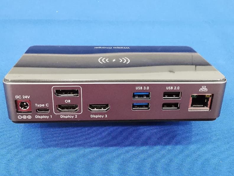
Click to zoom
Application Details
- Equipment Class
- DCD - Part 15 Low Power Transmitter Below 1705 kHz
- Date of Grant
- Apr 17, 2024
- Application Purpose
- Original Equipment
- Date of Application
- Apr 17, 2024
- Equipment Note
- 14-in-1 USBC 8K Docking Station CHD MST
- Frequency Range
- 0.11000000 - 0.20500000
- Company
- HPC Technology Inc.
- Country
- China
Documents & Files
Document Text
Text extracted from the exhibit documents filed with the FCC. Open a document above to read the original.
Users Manual
User Manual 14-in-1 USBC 8K Docking Station CHD MST Model: 265001 - 1 - Introduction 14-in-1 USBC 8K Docking Station CHD MST, the Pluggable Universal Laptop Docking Station for Windows and Mac allows you to add up to three monitors, and connect your peripherals, all through a single cable back to your laptop. Video output support SST、MST mode, and using different monitors to deal with different projects will make your work/life more efficient. Please Note: Mac OS only support mirror mode. Furthermore, the 14-in-1 USBC 8K Docking Station CHD MST comes with wireless charging 2-Coils Fast Charging - 1.4 times faster than standard wireless charger, built-in two coils offer you much wider charging area. This Quick Charge 2.0 - wireless charging will juice up your compatible device from dead to full in a short amount of time. Model: 265001 - 2 - Features • Expand the connectivity of your MacBook Pro, Chromebook, Dell XPS, or other USB-C enabled laptop, Thunderbolt 3/4 port compatible. • Power Delivery 3.0 100W function can supply power for your laptop. • Display port Resolution outputs max up to 8K@60Hz, support SST、MST. (Mac OS ONLY support mirror mode.) • Two USB-C 3.2ports, Two USB-A 3.0/2.0 ports, One Ethernet port up to 1Gbps and One Speaker/Microphone Output. • Support wireless charging of external devices. • Color format support YCbCr 4:4:4, 4:2:2 and 4:2:0 • High Dynamic Range (HDR) support Resolution Max (Input DP 1.4) Three Port: 4K2K 60Hz Dual Port: 8K4K 30Hz Single Port: 8K4K 60Hz Resolution Max (Input DP 1.2) Three Port: 4K2K 30Hz+1080P 60Hz *2 Dual HDMI Port: 4K2K 30Hz Single DP Port 4K2K 60Hz Required: Model: 265001 - 3 - 1. DisplayPort Alternate Mode on USB Type-C 2. It can support 8K60Hz only when the Device support DSC Mode Product Diagram ❶Select button: • Long press for 3 seconds to turn on or turn off the power. • Click the button to switch USB 3.2 max or USB 2.0 max Function. • Double click button to power on/off for Wireless charging LED. ❷3.5mm Audio/Microphone (CTIA Standard) ❸USB-C Host Port: • Used to connect the Host Computer to the Docking Station. • Power Delivery 3.0, Provide maximum 100W. • Compatible Thunderbolt 3/4, USB 4 ❹USB-C Device Ports: • Support data USB 3.2 Gen2 10 Gbps max Model: 265001 - 4 - • Maximum 5V/2A 10W of power output ❺SD Card Reader 4.0, SD 3.0, 2.0, 1.1, and 1.0 compatibility. ❻Reset: Reset to factory settings ❼Wireless charging: • Quick Charge 2.0 • Blue light when standby. • Green light flashes when charging. • Green light stays on when fully charged. • The red light flashes when it cannot be charged or there is a metal object in contact. ❽USB 3.2/USB 2.0 indicator light: • Click the select button to switch between USB3.2 or USB2.0 transmission speed. • When switching to USB3.2 Max, the maximum speed of USB-C 3.2 (ball number 4) can support up to 10 Gbps • When switching to USB3.2 Max, the maximum speed of USB-C 3.0 (ball number 11) can support up to 5 Gbps • When switching to USB2.0 Max, the maximum transmission speed of all USB data supports up to 480Mbps ❾DP1.4/DP1.2 indicator light: • Can detect the DP signal version of the image input, used to identify the Source device Model: 265001 - 5 - • DP1.4(DSC) can support up to 8K60Hz images, DP1.2 can support up to 4K60Hz images ※ Auto-detect of DisplayPort version will only be accessed when the output screen is connected ※ The output resolution will be subjected to the specification provided by the device manufacturer ❿RJ-45 Port: • Used to connect a Network Device to the Docking Station. • When switching to USB3.2 Max, the maximum speed up to 10/100/1000 Mbps • When switching to USB2.0 Max, the maximum speed up to 10/100 Mbps ⓫USB-A Device Ports • Support data USB 2.0 480 Mpbs max • Maximum 5V/0.5A 2.5W power output ⓬USB-A Device Ports: Model: 265001 - 6 - • Support data USB 3.0 5 Gbps max • Maximum 5V/1A 5W power output ⓭ “Display 3” HDMI output Port: • Using an HDMI Cable to Connect between Docking Station and HDMI Enabled Display Device. • HDMI 2.1 version • Resolution up to 7680x4320 60Hz ⓮“Display 2” DP or HDMI output Port: • Using DP or HDMI Cable Connect between the Docking Station and DP or HDMI Enabled Display Device. • HDMI 2.1 version • DP 1.4 version • Resolution up to 7680x4320 60Hz ※ ”Display 2” cannot output synchronously, only 1 port video output can be selected. ⓯“Display 1” Type-C output Port: • Using Type-C Cable Connect between the Docking Station and Type-C Enabled Display Device. • DP 1.4 version • Resolution up to 7680x4320 60Hz ⓰DC 24V Port Model: 265001 - 7 - • AC 110~240 DC 24V/5.5A 132W • Connect the Dock to a Power Source, using the Universal Power Adapter. ⓱Lock Slot • Used to secure the Docking Station to secure stationary object. Package Contents • USB-C Docking Station x 1 • 3 ft. (1m) USB-C Host Cable x 1 • Power Adapter x 1 • User Manual x 1 Storage Conditions Operating Temperature: 0°C to 70°C (32°F to 158°F) Storage Temperature:-30°C to 70°C (-22°F to 158°F) Operating Humidity: 20%~80%RH Storage Humidity: 20%~90%RH Model: 265001 - 8 - FCC Statement This device complies with Part 15 of the FCC Rules. Operation is subject to the following two conditions: (1)This device may not cause harmful interference. (2)This device must accept any interference received, including interference that may cause undesired operation. 2. Changes or modifications not expressly approved by the party responsible for compliance could void the user’s authority to operate the equipment. Note: This equipment has been tested and found to comply with the limits for a class Digital device, pursuant to Part 15 of the FCC Rules. These limits are designed to provide reasonable protection against harmful interference in a residential installation. This equipment generates uses and can radiate radio frequence energy and, if not installed and used in accordance with the instructions, may cause harmful interference to radio communications.However,there is no guarantee that interference will…
Text truncated - open the document above for the full version.
Attestation Statements
HPC Technology Inc. 2024-04-09 Eurofins Electrical and Electronic Testing NA, Inc. 914 West Patapsco Avenue Baltimore, MD 21230 RE: Attestation Statements Part 2.911(d)(5)(i) request for (FCC ID: 2BFAI-265001) [HPC Technology Inc.] (“the applicant”) certifies that the equipment for which authorization is sought is not “covered” equipment prohibited from receiving an equipment authorization pursuant to section 2.903 of the FCC rules. Sincerely, Shuwei Xu Hardware engineer HPC Technology Inc. 6F-1, No.700, Jhongjheng Rd., Jhonghe Dist., New Taipei City 235, Taiwan, R.O.C. HPC Technology Inc. 2024-04-09 Eurofins Electrical and Electronic Testing NA, Inc. 914 West Patapsco Avenue Baltimore, MD 21230 RE: Attestation Statements Part 2.911(d)(5)(ii) request for(FCC ID: 2BFAI-265001 ) [HPC Technology Inc.] (“the applicant”) certifies that, as of the date of the filing of the application, the applicant is not identified on the Covered List as an entity producing “covered” equipment. Sincerely, Shuwei Xu Hardware engineer HPC Technology Inc. 6F-1, No.700, Jhongjheng Rd., Jhonghe Dist., New Taipei City 235, Taiwan, R.O.C.
Attestation Statements
Attestation Statements (2024/4/13) TO: Federal Communications Commission Authorization and Evaluation Division 7435 Oakland Mills Road Columbia, MD 21046, USA RE: Attestation Statements Part 2.911(d)(7) request for (FCC ID:2BFAI-265001) (HPC Technology Inc.), the undersigned, hereby authorize Lucky Cowboy Global Services, LLC to act as our designated U.S. agent for service of process, (HPC Technology Inc.) accepts to maintain an agent for no less than one year after the grantee has terminated all marketing and importation or the conclusion of any Commission-related proceeding involving the equipment. Lucky Cowboy Global Services, LLC accepts the responsibility to act as designated U.S. agent for service of process. Applicant Information: Company Name: HPC Technology Inc. Contact Name: Shuwei Xu Address: 6F-1, No.700, Jhongjheng Rd., Jhonghe Dist., New Taipei City 235, Taiwan, R.O.C. FRN: 0035066448 Telephone No: 886-2-8226-3003 Email: [email protected] Signature [Shuwei Xu] U.S. Agent Information: Company Name: Lucky Cowboy Global Services, LLC Address: 2213 S. Braeswood Blvd. #12E Houston, TX 77030 USA FRN: 0033510934 Contact Name: Louie Liu Telephone No: +1 (713) 992-3369 Email: [email protected] Signature [Louie Liu]
External Photos
External
Internal Photos
Internal Wireless Charging Antenna
RF Exposure Info
EUT Specification FCC ID: 2BAFI- 265001 Characteristics Description Product Name 14-in-1 USBC 8K Docking Station CHD MST Model number 265001 Series number N/A Rating Input: 24.0Vdc, 5.5A; Output: USB 2.0: 5.0Vdc,0.5A; USB 3.0: 5.0Vdc,1A; USB-C 3.2: 5.0Vdc,2A; USB-C Host: 20.0Vdc,5A; Wireless Charging: 15.0W Max Operating Frequency Range 110-205KHz Modulation Technique ASK Antenna Type Coil Antenna Device category Portable (<20cm separation) Mobile (>20cm separation) Others ___ Antenna diversity Single antenna Multiple antennas Tx diversity Rx diversity Tx/Rx diversity Evaluation applied MPE Evaluation SAR Evaluation 2 Applicable Standard: FCC Part 1(1.1310), Part 2(2.1093) and KDB 680106 D01 RF Exposure Wireless Charging Apps v04 Applicable Requirement: Three different categories of transmitters are defined by the FCC in OET Bulletin 65. These categories are fixed installation, mobile, and portable and are defined as follows: Fixed Installations: fixed location means that the device, including its antenna, is physically secured at a permanent location and is not able to be easily moved to another location. Additionally, distance to humans from the antenna is maintained to at least 2 meters. Mobile Devices: a mobile device is defined as a transmitting device designed to be used in other than fixed locations and to be generally used in such a way that a separation distance of at least 20 centimeters is normally maintained between the transmitter's radiating structures and the body of the user or nearby persons. Transmitters designed to be used by consumers or workers that can be easily re-located, such as a wireless modem operating in a laptop computer, are considered mobile devices if they meet the 20 centimeter separation requirement. The FCC rules for evaluating mobile devices for RF compliance are found in 47 CFR ß2.1091. Portable Devices: a portable device is defined as a transmitting device designed to be used so that the radiating structure(s) of the device is/are within 20 centimeters of the body of the user. Portable device requirements are found in Section 2.1093 of the FCC's Rules (47 CFRß2.1093). The FCC also categorizes the use of the device as based upon the user’s awareness and ability to exercise control over his or her exposure. The two categories defined are Occupational/ Controlled Exposure and General Population/Uncontrolled Exposure. These two categories are defined as follows: Occupational/controlled exposure limits apply in situations in which persons are exposed as a consequence of their employment provided those persons are fully aware of the potential for exposure and can exercise control over their exposure. Limits for occupational/controlled exposure also apply in situations when a person is transient through a location where occupational/controlled limits apply provided he or she is made aware of the potential for exposure. The phrase fully aware in the context of applying these exposure limits means that an exposed person has received written and/or verbal information fully explaining the potential for RF exposure resulting from his or her employment. With the exception oftransient persons, this phrase also means that an exposed person has received appropriate training 3 regarding work practices relating to controlling or mitigating his or her exposure. Such training is not required for transient persons, but they must receive written and/or verbal information and notification (for example, using signs) concerning their exposure potential and appropriate means available to mitigate their exposure. The phrase exercise control means that an exposed person is allowed to and knows how to reduce or avoid exposure by administrative or engineering controls and work practices, such as use of personal protective equipment or time averaging of exposure. General population/uncontrolled exposure limits apply in situations in which the general public may be exposed, or in which persons who are exposed as a consequence of their employment may not be fully aware of the potential for exposure or cannot exercise control over their exposure. Licensees and applicants are responsible for compliance with both the occupational/controlled exposure limits and the general population/uncontrolled exposure limits as they apply to transmitters under their jurisdiction. Licensees and applicants should be aware that the occupational/controlled exposure limits apply especially in situations where workers may have access to areas in very close proximity to antennas and access to the general public may be restricted. In lieu of evaluation with the general population/uncontrolled exposure limits, amateur licensees authorized under part 97 of this chapter and members of his or her immediate household may be evaluated with respect to the occupational/controlled exposure limits in this section, provided appropriate training and information has been provided to the amateur licensee and members of his/her household. Other nearby persons who are not members of the amateur licensee's household must be evaluated with respect to the general population/uncontrolled exposure limits. Test Setup Block 4 Test Procedure 5 1.Connect the EUT and equipment as above diagram of test configuration. 2.EUT was placed on a table, and the measure probe was placed at a measurement distance of 15cm from the EUT to the center of the probe. 3.Power on the measuring probe, the EUT was set at the maximum field strength emission state. 4.The EUT was put in different directions (Left, Right, Front, Rear, Top and Bottom) toward to the measure probe. The distance from the top of the EUT to the probe is 20CM, and the distance from other directions is 15cm.Measure the value of field strength. 5.Record the worst data of the different directions. Measuring Device And Test Equipment Used Equipment Manufacturer Model No. Serial No. Next Cal. Cal. Interval E&H-Field Probe(9kHz-30M Hz) Narda EHP-200A 180ZX11012 Sep. 21, 2024 1 Year D…
Text truncated - open the document above for the full version.
Test Report
Specification Model JOINTLY-3S1512-01 Version 1.1 2021.02.01 Customer Approval 深圳市麒墅科技有限公司 批准 Approved 营业确认 Checked by Sales Dept. 标准化审核 Standard Checked 技术确认 Checked by Technical Dept. 制作 Prepared 曾智伟 2020.4.3 毛晶 2020.4.3 徐相德 2020.4.3 贾玉山 2020.4.3 简丹 2020.4.3 变更履历 RevisionHistory 无线充电产品规格书 版本 Rev. 日期 Date 变更前 Previous 改进 Revised 备注 Remark 1.0 2019-03-01 (初版) Original Release -- 1.0.1 2019-05-11 1.0 Add constant frequency voltage regulation 1.1.0 2020-03-8 1.0.1 1.1.1 2020-07-8 1.1.0 Upgrade the resonant capacitor, 50V to 100V, improve the sensing distance 1.2 2021-02-01 1.1.1 Increased voltage detection 无线充电产品规格书 目录 Contents 1.无线充电模块简述Wirelesschargingmodulebrief........................................1 2.电路原理框图Circuitblockdiagram...............................................................1 3.电气连接Electricalconnection........................................................................2 4.基本参数Basicparameters.................................................................................2 5.关键特性Wirelesschargingmodulecharacteristics.........................................3 6.系统性能参数Systemperformanceparameters.............................................3 7.有效工作区域Effectiveworking..........................................................................4 8.控制逻辑Controllogic............................................................................4 9.可靠性试验ReliabilityTest.................................................................................5 10.散热可靠性Thermal............................................................................................6 11.寿命测试实验Agingtest.....................................................................................6 12.散热可靠性Thermalreliability.........................................................................8 13.线圈规格Coilspecifications...................................................................................8 14.注意事项Caution..................................................................................................8 15.产品外形尺寸图ProductDimensions...............................................................10 无线充电产品规格书 1 1.无线充电模块简述Wirelesschargingmodulebrief 此手机无线充电发射模块,适用于12V电源系统。此模块采用ST公司的芯片,WPCQi标准,MP-A6 三线圈。芯片内置了FOD保护功能,即发射功率减去接收端RX回传的有效功率数据,就近似得到寄生 金属发热损耗功率的大小。通过设定FOD的保护门限,间接限制了手机寄生金属损耗的温升值。 Thephonewirelesschargingtransmittermoduleappliesto12Vpowersystem.ThismoduleusesST's chip,WPCQistandard,MP-A6threecoils.chipbuilt-inFODprotectionfunction,transmitpower minustheeffectivepowerdataofreceivingendRXreturn,approximatedgetparasiticheatlosspower.By settingtheFODprotectionthreshold,indirectlylimitthephoneparasiticlosstemperaturerise. wirelesschargingsystemblockdiagram 2.电路原理框图Circuitblockdiagram 此产品能在9V~16V的电压范围内工作。同时供电电路需要增加滤波、 抗抑制、过压、过流保护、防反接功能。 Thisproductcanworkinthevoltagerangeof9V-16V.Atthesametimepowersupplycircuitneedstoincrease filtering,anti-suppression,overvoltage,overcurrentprotection,anti-reversefunction. 2 无线充电产品规格书 3.电气连接Electricalconnection 引脚序号定义Pinnumberdefinition 引脚定义表 脚位 PIN 功能 Function 说明 Description 规格Specification 1V+ 电源正VCC 耐压(Voltageresistance):-25V~+25V 2V- 电源负GND 4.基本参数 Basic parameters 符号 Symbol 描述Description条件Conditions Min TypMax 单位 Unit 输入特性Inputcharacteristics V in 工作电压 WorkingVoltage CHARGING91216V I in 工作电流 Workingcurrent CHARGING0.120.72.5A I pc 待机电流Standby current PING102040mA I sc 静态电流 QuiescentCurrent ACC关断 ACCturnsoff 00.1mA 输出特性Outputcharacteristics P out 输出功率 OutputPower 515W 系统特性Systemcharacteristics η peak 最大转换效率 Maximumconversion efficiency 负载≥3W Load≥3W 6068 80 % 3 无线充电产品规格书 Fs 工作频率 workingfrequency CHARGING110205KHz 温度特性Temperaturecharacteristics T o 工作温度 Workingtemperature -402585 °C Ts 储存温度 Storagetemperature -5525105 °C Tr 充电温升 Chargingtemperature rise 环境温度25°C Environment temperature25°C 1015 °C 5.关键特性Wirelesschargingmodulecharacteristics 9V~16V供电 9V~16Vpowersupply WPCQi1.2标准 WPCQi1.2.4standard MP-A6三线圈 MP-A6typethreecoils 过电压保护(OVP) Overvoltageprotection 过电流保护(OCP) Overcurrentprotection 过温度保护(OTP) Overtemperatureprotection FOD保护 ForeignObjectDetection(FOD)protection LED灯显示充电状态 LEDdisplaychargingstatus 电源转换效率最高80% EnergyConvertEfficiency80% 6.系统性能参数Systemperformanceparameters 输入电压范围 Inputvoltagerange DC9V~16V 输入电流Inputcurrent45mA~2500mA(MAX)(VIN=12V) 待机电流Standbycurrent <50mA。(VIN=12V,typicalvaluesaround35mA) 输出功率Outputpower15W(MAX) 最大转换效率Themaximum conversionefficiency 80%(常温25°C环境下测试,用稳压源读取输出电压、电流,用电 子负载读取负载功率值,然后进行计算。25°Cenvironment temperaturetest.Weusetheregulatortoreadtheoutputvoltageand current,andtheelectronicloadtoreadtheloadpowervalue,then calculated) 无线充电标准 Wirelesschargingstandard WPCQi1.2.4 发射频率 Transmissionfrequency 110kHz~205kHz 无线充电Z轴距离Wireless chargingZ-axisdistance 外壳表面0mm~6mm(max)(过Qi认证,不建议增厚。Asthe product needtothroughQicertification,wedonotproposetothicken) 4 无线充电产品规格书 线圈类型CoilTypeMP-A6三线圈MP-A6typethreecoils FOD寄生金属损耗设定 FODparasiticlossesset 按Qi1.2.4标准设定寄生金属损耗,大于此额外损耗就关闭充电。 SettingparasiticlossesaccordingtoQi1.2.4standards,offthecharge whengreaterthantheadditionallosses. 保存温度Storagetemperature-55°C~105°C 工作温度 Workingtemperature -40°C~85°C(无线充电器端可以满足此温度范围,但是手机是消费类产 品,不支持高温工作,手机锂电池不能高于60°C。 Wirelesschargerendsmeetthistemperaturerange,butthephoneisa consumerproduct,donotsupporthightemperaturesoperation,cellphone lithium batterycannotabove60°C.) 自由充电面积Freechargingarea 70mm×30mm PCB尺寸PCBsize 97mm×55mm 外形尺寸Dimensions 132.1mm×73mm×21mm 保护功能Protection 有过流保护、过压保护、短路保护、过热保护。Overcurrentprotection, Overvoltageprotection,Shortcircuitprotection,Overtemperature protection. 充电状态指示 Chargingstatusprompt 白、兰LED灯指示充电状态。whiteandbuleLEDlightsindicate chargingstatus. 环保方面 Environmentalprotection 满足RoHS要求。MeettheRoHSrequirements. 5 无线充电产品规格书 7.有效工作区域Effectiveworkingarea X轴可移动区域:-15mm~15mm,X-axischargeablearea:-15mm~15mm Y轴可移动区域:-35mm~35mm,Y-axischargeablearea:-35mm~35mm 6 无线充电产品规格书 Z轴可移动区域:外壳表面0mm~8mm,Z-axis chargeable area:Shell surface 0mm~8mm 8 .控制逻辑 Controllogic LED灯指示逻辑状态: LED lights indicate logical status: LED颜色 LED color LED运行状态LED operating status 待机 Standby 充电 Charging …
Text truncated - open the document above for the full version.
Test Report
TRF No.: 04-E001-0B TRF Originator: GTG TRF Date: 2023-12-13 Web: www.gtggroup.com E-mail: [email protected] Tel.: 86-400 755 8988 ELECTROMAGNETIC EMISSIONS COMPLIANCE REPORT INTENTIONAL RADIATOR CERTIFICATION TO FCC PART 15 SUBPART C REQUIREMENT OF 14-in-1 USBC 8K Docking Station CHD MST Model No.: 265001 FCC ID: 2BFAI-265001 Report No.: E04A23100693F00501 Issue Date: Jan. 20, 2024 Prepared for HPC Technology Inc. 6F-1, No.700, Jhongjheng Rd., Jhonghe Dist., New Taipei City 235, Taiwan, R.O.C. Prepared by Guangdong Global Testing Technology Co., Ltd. Room 101-105, 203-210, Building 1, No.2, Keji 8 Road, Songshan Lake Park, Dongguan city, Guangdong, People ’s Republic of China, 523808 This report is based on a single evaluation of the submitted sample(s) of the above mentioned Product, it does not imply an assessment of the production of the products. This report shall not be reproduced, except in full, without the written approval of Guangdong Global Testing Technology Co., Ltd. Page 1 of 41 Report No.: E04A23100693F00501 TRF No.: 04-E001-0B Global Testing , Great Quality. VERIFICATION OF COMPLIANCE Applicant: HPC Technology Inc. 6F-1, No.700, Jhongjheng Rd., Jhonghe Dist., New Taipei City 235, Taiwan, R.O.C. Manufacturer: HPC Technology Inc. 6F-1, No.700, Jhongjheng Rd., Jhonghe Dist., New Taipei City 235, Taiwan, R.O.C. Product Description: 14-in-1 USBC 8K Docking Station CHD MST Model Number: 265001 Series Model: N/A Brand: HPC Technology Inc. We hereby certify that: The above equipment was tested by Guangdong Global Testing Technology Co., Ltd. The test data, data evaluation, test procedures, and equipment configurations shown in this report were made in accordance with the procedures given in ANSI C63.10-2013 and the energy emitted by the sample EUT tested as described in this report is in compliance with conducted and radiated emission limits of FCC Rules Part 15.209(2022). Date of Test: Jan. 17, 2024 to Jan. 20, 2024 Prepared by: Alan He/Editor Reviewer & Authorized Signer: Shawn Wen/ General Manager Page 2 of 41 Report No.: E04A23100693F00501 TRF No.: 04-E001-0B Global Testing , Great Quality. Modified Information Version Summary Revision Date Report No. Ver.1.0 Original Report / E04A23100693F00501 Page 3 of 41 Report No.: E04A23100693F00501 TRF No.: 04-E001-0B Global Testing , Great Quality. Table of Contents 1 GENERAL INFORMATION ............................................................................................................................. 4 1.1 PRODUCT DESCRIPTION .............................................................................................................................. 4 1.2 RELATED SUBMITTAL(S) / GRANT(S) ........................................................................................................... 5 1.3 TEST METHODOLOGY .................................................................................................................................. 5 1.4 SPECIAL ACCESSORIES ............................................................................................................................... 5 1.5 EQUIPMENT MODIFICATIONS ....................................................................................................................... 5 1.6 TEST FACILITY.............................................................................................................................................. 5 2 SYSTEM TEST CONFIGURATION ................................................................................................................ 6 2.1 EUT CONFIGURATION ................................................................................................................................. 6 2.2 EUT EXERCISE ............................................................................................................................................ 6 2.3 TEST PROCEDURE ....................................................................................................................................... 6 2.4 CONFIGURATION OF TESTED SYSTEM ......................................................................................................... 6 3 SUMMARY OF TEST RESULTS .................................................................................................................... 8 4 TEST SYSTEM UNCERTAINTY ..................................................................................................................... 9 5 CONDUCTED EMISSIONS TEST ................................................................................................................ 10 5.1 MEASUREMENT PROCEDURE .................................................................................................................... 10 5.2 TEST SET-UP (BLOCK DIAGRAM OF CONFIGURATION) ........................................................................... 10 5.3 MEASUREMENT EQUIPMENT USED............................................................................................................ 10 5.4 CONDUCTED EMISSION LIMIT .................................................................................................................... 10 5.5 MEASUREMENT RESULT ............................................................................................................................ 11 5.6 CONDUCTED MEASUREMENT PHOTO ........................................................................................................ 14 6 RADIATED EMISSION TEST........................................................................................................................ 15 6.1 MEASUREMENT PROCEDURE .................................................................................................................... 15 6.2 TEST SET-UP (BLOCK DIAGRAM OF CONFIGURATION) ........................................................................... 15 6.3 MEASUREMENT EQUIPMENT USED.......................................................................…
Text truncated - open the document above for the full version.
Test Setup Photos
Conducted Measurement Photo Radiated Measurement Photos 9kHz-30MHz 30MHz-1GHz
Contact Information
Applicant
Shuwei Xu(Hardware engineer)
Technical Contact
Guangdong Global Testing Technology Co., Ltd.Shawn Wen
[email protected]+8676985075888
Room 101-105,203-210, Building 1, No.2, Keji 8 · Dongguan, Guangdong · China
Non-Technical Contact
Guangdong Global Testing Technology Co., Ltd.Shawn Wen
[email protected]+8676985075888
Test Firm
Guangdong Global Testing Technology Co., Ltd.Shawn Wen
[email protected]86 769 8507 5888
Technical Specifications
| # | Rule Parts | Frequency Range | Power Output |
|---|---|---|---|
| 1 | 15C | 0.11 MHz - 0.205 MHz | - |