2BFLB-DS04Belt Drive Layered Turntable with Built-in Speakers
Shenzhen Stack Stone Technology Inc.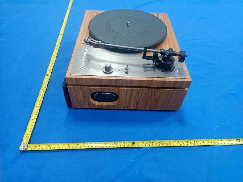
Click to zoom
Application Details
- Equipment Class
- DSS - Part 15 Spread Spectrum Transmitter
- Date of Grant
- Apr 07, 2024
- Application Purpose
- Original Equipment
- Date of Application
- Apr 07, 2024
- Equipment Note
- Belt Drive Layered Turntable with Built-in Speakers
- Frequency Range
- 2402.00000000 - 2480.00000000
- Country
- China
Documents & Files
Document Text
Text extracted from the exhibit documents filed with the FCC. Open a document above to read the original.
Users Manual
SAVAGE AUDIO Belt Drive Layered Turntable with Built in Speakers SAVAGE THE ONE Instruction Manual ... 1 Thank you for purchasing the SAVAGE AUDIO All-in-One Record Player, Savage The One. Please read the operation manual carefully before use. This manual contains important information such as safety precautions and usage instructions. Please keep it in a safe place for future reference. When reselling or gifting this product, be sure to include this manual. 1. Please follow the instructions in the manual for the proper use of this product. 2. Avoid exposing the product to rain, moisture, dripping, or splashing water. 3. Ensure that the power voltage matches the voltage indicated on the product. 4. Do not modify the plug in any way. 5. Avoid pulling, bending, stepping on, or squeezing the power cord. 6. Assemble the product according to this manual, and do not place any objects on the product. 7. Prevent any objects or liquids from entering the turntable body, as they may come into contactwith hazardous voltage points or cause components to short circuit, leading to fire or electricshock. 8. Do not attempt to repair the turntable or remove the body panel by yourself. Leave allmaintenance work to qualified service personnel. 9. Do not use any turntable replacement parts or components not approved by the manufacturerin this product. 10. Do not place the product near any high-temperature areas or open flames.Place the product on a flat and stable surface, and handle it with care during moving or 11.transportation to prevent overturning and collisions that may cause damage. 12. The slots and openings on the body ensure ventilation and reliable operation of the product,preventing excessive heat. Do not block or cover these openings. 13. Unplug the power cord during thunderstorms or when the product is not in use for an extendedperiod. INTRODUCTION SAFETY INSTRUCTIONS 2 COMPONENT NAMES 1. Motor pulley 2. Drive Belt 3. Turntable Spindle 4.Turntable Sub-platter 5. Turntable Platter 6. Counterweight 7. Balance bar 8. Tonearm Lift Lever 9. Tonearm Clip 10. Function switch 11. 33/45RPM Selector 12.Indicator light 13. Volume Control 14. Tonearm Rest 15.Stylus Cartridge 16.Protective cover 17.Ground Connector 18. Phono & Line Out Switch 19.Phono & Line Out Jacks 20. Speed fine adjustment 21.DC INPUT Jack 1 2 3 4 5 6 8 9 13 15 17 19 1820 21 7 10 11 12 14 16 3 Before installation, please check that the following components are included and undamaged. Keep the original packaging for potential returns or exchanges. Note: The turntable is factory-equipped with a pre-aligned cartridge. Instructions for adjusting the cartridge, as provided in the manual, are intended for use when replacing the cartridge. 1)Turntable Body 2)Power Adapter 3)Turntable Dust Cover 4)Anti-slip Mat 5)Main Platter 6)Sub Platter 7) Belt 8)Counterweight 9)Cartridge Alignment Card 10)45 RPM Record Adapter 11)User Manual -Mount the product on a level surface.. -To avoid the effects of vibrations and acoustic pressure, do not mount the productnext to such items as speakers. -The product may pick up radio static if placed next to a radio. Therefore, try to keepthe product away from radios. -lf the product is near equipment (cell phone, etc.) that emits strong radio wavesnoise may occur. Pull out the four shock-absorbing pads of the turntable and place them properly. Reinsert the shock-absorbing pads into their original positions the next time you transport the turntable. Cartridge damping pad INCLUDED LTEMS INSTALLING THE TURNTABLE Note: Do not apply power before completing the assembly. REMOVE THE CARTRIDGE DAMPING PAD 4 TURNTABLE PLATTER AND BELT SETUP 1.Put the belt on the motor pulley and the sub platter in the correct position as shown in the figure, taking care not to twist the belt. 2.Manually rotate the sub platter clockwise about 10 circles. -Check if the belt is twisted or detached to ensure smooth operation of the turntable drive system. 3 .Carefully place the main platter on top of the sub-platter. 5 CARTRIDGE TRACKING FORCE ADJUSTMENT 4.Place the slip mat on the platter with the SAVAGE AUDIO logo facing up. 1.Gently push the counterweight onto the rear of the tonearm. 2. Carefully push and pull the Counterweight and stop when it reaches the tick markof recommended tracking force. Note: Each mark on the dial represents 0.5g.The recommended tracking force forthe factory- installed cartridge is 2.5g±0.5. Tonearmcounterweight 6 3. lf the counterweight loosens or moves during the usage, please gently turn thescrew to make it tight again. INSTALLING THE TURNTABLE DUST COVER When the turntable is working: remove the dust cover and put on the record. When the turntable is not working: remove the record and put on the dust cover to protect the tonearm and platter. 7 Connection to External Speakers with RCA Note: In order to achieve the best sound, it is advised to set the turntablevolume to a minimal level. Then the turntable's audio will be played back throughyour own amplifier, speakers, etc. This product includes 4 built-in speakers and a built-in phono equalizer. If you want to use your own amplifier or speakers, please follow the instructions below: Active Speakers Amplifier or 1.Set the preamplifier selector switch (PHONO/LINE output selection) This product has a built-in phono equalizer function. You can use the product evenif you do not have a phono amplifier or connectable equipment with a built-inphono amplifier. Use the Phono & Line Out Switch to set the output, as shown below. Note: The RCA Jacks are not designed to be connected directly to thepassive/unpowered speakers on LlNE mode. lf connected to the passivespeakers, there will be no sound. If you need to use passive speakers, please use a separate power amplifier. Connected equipmentbeing used Position of the Phono &Line Out Switch Where to connect RCAaudio cable Device with phono inputPHONOPhono input jack andground (earth) terminal ofconnected equipment Device witho…
Text truncated - open the document above for the full version.
Attestation Statements
Shenzhen Stack Stone Technology Inc. Room 909, Block A, Building 1, Zuoyouyunchuanggu, No. 8, Pinglang Road, Xialilang Community, Nanwan Street, Longgang District, Shenzhen China Federal Communications Commission Authorization and Evaluation Division Equipment Authorization Branch 7435 Oakland Mills Road Columbia, MD 21046 2024-4-2 To whom it may concern: We, Shenzhen Stack Stone Technology Inc., hereby certify that the equipment for which authorization is sought (FCC ID: 2BFLB-DS04) is not “covered” equipment prohibited from receiving an equipment authorization pursuant to § 2.903 of the FCC rules. We also certify that, as of the date of the filing of the application, we are not identified on the Covered List (https://www.fcc.gov/supplychain/coveredlist) as an entity producing “covered” equipment. By signing this form, we confirm the above and that we are aware of the application requirements listed under § 2.911(b) and (d)(5) and (6). The information provided in this letter is based on the referenced rule parts of Title 47 of the CFR as well as KDB 986446 D01. Sincerely, Signature Yifan Liu Manager Shenzhen Stack Stone Technology Inc. 62_[model] CoveredEqu_2.911(d)(5)(i) and (ii) - U, V03
Attestation Statements
Shenzhen Stack Stone Technology Inc. Room 909, Block A, Building 1, Zuoyouyunchuanggu, No. 8, Pinglang Road, Xialilang Community, Nanwan Street, Longgang District, Shenzhen, China Federal Communications Commission Authorization and Evaluation Division Equipment Authorization Branch 7435 Oakland Mills Road Columbia, MD 21046 2024/03/27 U.S. Agent Designation Shenzhen Stack Stone Technology Inc. acknowledges their consent for the following contact located in the United States to act as their agent for service of process for the equipment for which authorization is sought (FCC ID: 2BFLB-DS04): Name and company of U.S. agent: GSS SERVICE INC Physical U.S. address of agent: 6547 N Academy Blvd #2266 Colorado Springs COLORADO 80918 United States FRN of U.S. agent: 0033402082 Email address of U.S. agent: [email protected] GSS SERVICE INC acknowledges their obligation to accept service of process on behalf of Shenzhen Stack Stone Technology Inc. Shenzhen Stack Stone Technology Inc with the FRN [0035185339] accepts its obligation to maintain an agent for service of process in the United States for no less than one year after either the grantee has permanently terminated all marketing and importation of the applicable equipment within the U.S., or the conclusion of any Commission-related administrative or judicial proceeding involving the equipment, whichever is later. By signing this form, we confirm the above and that we are aware of the application requirements listed under § 2.911(d)(7). The information provided in this letter is based on the referenced rule parts of Title 47 of the CFR as well as KDB 986446 D01. An expiration date for this letter does not exist. In case the U.S. agent changes, the grantee is obligated to notify the FCC within 30 days via the granting TCB. Sincerely, Signature Yifan Liu Manager Shenzhen Stack Stone Technology Inc. Signature Michoux Logan PM GSS SERVICE INC 48_[mo del] US_Agent_2.911(d)(7) - U, V0 5
Cover Letter(s)
Shenzhen Stack Stone Technology Inc. Add: Room 909, Block A, Building 1, Zuoyouyunchuanggu, No. 8, Pinglang Road, Xialilang Community, Nanwan Street, Longgang District, Shenzhen China Date: 2024-4-2 FCC ID: 2BFLB-DS04 Dear Sir/Madam, We, Shenzhen Stack Stone Technology Inc. Hereby declares the following statement for Federal Communications Commission, PCB board, circuit, structure and internal of these model(s) are the same, Only model number is different for these model: Product name: Belt Drive Layered Turntable with Built-in Speakers Model no.: DS04, DS14, DS24, DS34 Sincerely, Name/Title: Yifan Liu/Manager Company: Shenzhen Stack Stone Technology Inc. Address: Room 909, Block A, Building 1, Zuoyouyunchuanggu, No. 8, Pinglang Road, Xialilang Community, Nanwan Street, Longgang District, Shenzhen China Phone: 18165740680 Fax: N/A E-Mail: [email protected]
Cover Letter(s)
CONFIDENTIALITY REQUEST for Certification Service in USA Federal Communication Commission Equipment Authorization Division, Application Processing Branch 7435 Oakland Mills Road Columbia, MD 21046 Date:<2024-4-2> Pursuant to Paragraphs §0.457 and 0.459 of the Commission’s Rules (47 C.F.R.) and Section §552(b)(4) of the Freedom of Information Act, we requests confidentiality for the following products: FCC ID Model name 2BFLB-DS04 DS04 For the product stated above, we request that the following information be held confidential; Exhibits Long-Term Confidentiality Short-Term Confidentiality Short-Term Confidentiality Days External Photos Internal Photos Block Diagram Schematics Test Setup Photos User’s Manual Parts List Tune Up Operational Descriptions The long-term confidentiality exhibits contain our trade secrets and proprietary information that could be of benefit to our competitors. The short-term confidentiality on the basis of ensuring that business sensitive information remains confidential until the actual marketing of our new device. If you have any questions, please feel free to contact me at the address shown below. Sincerely, Name/Title: Yifan Liu/Manager Company: Shenzhen Stack Stone Technology Inc. Address: Room 909, Block A, Building 1, Zuoyouyunchuanggu, No. 8, Pinglang Road, Xialilang Community, Nanwan Street, Longgang District, Shenzhen China Phone: 18165740680 Fax: N/A E-Mail: [email protected]
Cover Letter(s)
Shenzhen Stack Stone Technology Inc. Room 909, Block A, Building 1, Zuoyouyunchuanggu, No. 8, Pinglang Road, Xialilang Community, Nanwan Street, Longgang District, Shenzhen China Federal Communications Commission Authorization and Evaluation Division Equipment Authorization Branch 7435 Oakland Mills Road Columbia, MD 21046 2024-4-2 To whom it may concern: We, the undersigned, hereby authorize Eurofins Product Service GmbH to act on our behalf in all matters relating to applications for equipment authorization FCC ID: 2BFLB-DS04 including the signing of all documents related to these matters. Any and all acts carried out by Eurofins Product Service GmbH on our behalf shall have the same effect as acts of our own. By signing this application form, we agree to Eurofins’ current valid General Terms and Conditions (AGB),Testing and Certification Regulations (PZO) which can be viewed on following website www.eurofins.de/ee or retrieved on request. We also hereby certify that no party to this application is subject to a denial of benefits, including FCC benefits, pursuant to Section 5301 of the Anti-Drug Abuse Act of 1988, 21 U.S.C. 862. Sincerely, Name/Title: Yifan Liu/Manager Company: Shenzhen Stack Stone Technology Inc. Address: Room 909, Block A, Building 1, Zuoyouyunchuanggu, No. 8, Pinglang Road, Xialilang Community, Nanwan Street, Longgang District, Shenzhen China Phone: 18165740680 Fax: N/A E-Mail: [email protected]
External Photos
FCC ID: 2BFLB-DS04 External Photos of the EUT FCC ID: 2BFLB-DS04 FCC ID: 2BFLB-DS04
ID Label/Location Info
80x40mm Label location 2BFLB-DS04
Internal Photos
FCC ID: 2BFLB-DS04 Internal Photos of the EUT FCC ID: 2BFLB-DS04 FCC ID: 2BFLB-DS04 FCC ID: 2BFLB-DS04 BT PCB Antenna
RF Exposure Info
RF Exposure evaluation FCC ID: 2BFLB-DS04 1.1. Applicable Standard According to §1.1307(b)(1), systems operating under the provisions of this section shall be operated in a manner that ensures that the public is not exposed to radio frequency energy level in excess of the Commission’s guidelines. According to §1.1310 and §2.1093 RF exposure requirement KDB447498 v06: Mobile and Portable Devices RF Exposure Procedures and Equipment Authorization Policies 1.2. Requirement According to KDB447498 D01 General RF Exposure Guidance v06 Section 4.3.1 Standalone SAR test exclusion considerations: “Unless specifically required by the published RF exposure KDB procedures, standalone 1-g head or body and 10-g extremity SAR evaluation for general population exposure conditions, by measurement or numerical simulation, is not required when the corresponding SAR Test Exclusion Threshold condition, listed below, is satisfied. These test exclusion conditions are based on source-based time-averaged maximum conducted output power of the RF channel requiring evaluation, adjusted for tune-up tolerance, and the minimum test separation distance required for the exposure conditions.22 The minimum test separation distance is determined by the smallest distance from the antenna and radiating structures or outer surface of the device, according to the host form factor, exposure conditions and platform requirements, to any part of the body or extremity of a user or bystander (see 5) of section 4.1). To qualify for SAR test exclusion, the test separation distances applied must be fully explained and justified by the operating configurations and exposure conditions of the transmitter and applicable host platform requirements, typically in the SAR measurement or SAR analysis report, according to the required published RF exposure KDB procedures. When no other RF exposure testing or reporting is required, a statement of justification and compliance must be included in the equipment approval, in lieu of the SAR report, to qualify for the SAR test exclusion. When required, the device specific conditions described in the other published RF exposure KDB procedures must be satisfied before applying these SAR test exclusion provisions; for example, handheld PTT two-way radios, handsets, laptops & tablets etc.23 “ [(max. power of channel, including tune-up tolerance, mW)/ (min. test separation distance, mm)] · [√f (GHz)] ≤ 3.0 for 1-g SAR and ≤ 7.5 for 10-g extremity SAR, where: • f (GHz) is the RF channel transmit frequency in GHz • Power and distance are rounded to the nearest mW and mm before calculation • The result is rounded to one decimal place for comparison • 3.0 and 7.5 are referred to as the numeric thresholds in the step 2 below The test exclusions are applicable only when the minimum test separation distance is ≤ 50 mm and for transmission frequencies between 100 MHz and 6 GHz. When the minimum test separation distance is < 5 mm, a distance of 5 mm according to 5) in section 4.1 is applied to determine SAR test exclusion. 1.3. Manufacturing tolerance GFSK (Peak) Channel Channel 0 Channel 39 Channel 78 Target (dBm) 1.0 -2.0 -4.0 Tolerance ±(dB) 1.0 1.0 1.0 π/4DQPSK (Peak) Channel Channel 0 Channel 39 Channel 78 Target (dBm) 0.0 -2.0 -4.0 Tolerance ±(dB) 1.0 1.0 1.0 8DPSK (Peak) Channel Channel 0 Channel 39 Channel 78 Target (dBm) 1.0 -2.0 -4.0 Tolerance ±(dB) 1.0 1.0 1.0 Page 2 of 2 2. E v a l u a t i o n R e s u l t Evaluation Results Band/Mode f (GHz) Antenna Distance (mm) RF output power (including tune-up tolerance) SAR Test Exclusion Threshold SAR Test Exclusion dBm mW BT 2.450 5 2.0 1.5849 0.4962<3.0 Yes 3. C o n c l u s i o n The measurement results comply with the FCC Limit per 47 CFR 2.1093 for the uncontrolled RF Exposure and SAR Exclusion Threshold per KDB 447498 v06 .....................End of Report.........................
Test Report
1. Antenna Description: Antenna type PCB antenna Model DS04 Frequency range 2400-2500MHz Manufacturer Dongguan Hongsheng technology development Co., LTD ANT Peak Gain 0.75 dBi 2. Antenna Photo: Length: 12.51mm Width: 3.87mm 3. Test Equipment & Conditions 3.1 Test instrument VSWR is tested using Agilent E5071B connected to a hand mechanism, and the status is free space. 3.2 Test environment and methods 4.Antenna Radiation Pattern 2400MHz 2450MHz 2500MHz
Test Report
Shenzhen CTA Testing Technology Co., Ltd. Room 106, Building 1, Yibaolai Industrial Park, Qiaotou Community, Fuhai Street, Bao’an District, Shenzhen, China Shenzhen CTA Testing Technology Co., Ltd. Room 106, Building 1, Yibaolai Industrial Park, Qiaotou Community, Fuhai Street, Bao’an District, Shenzhen, China Tel:+86-755 2322 5875 E-mail:[email protected] Web:http://www.cta-test.cn FCC PART 15 SUBPART C TEST REPORT FCC PART 15.247 Report Reference No. ..................... : FCC ID............................................. : CTA24030800601 2BFLB-DS04 Compiled by ( position+printed name+signature) . : File administrators Zoey Cao Supervised by ( position+printed name+signature) . : Project Engineer Amy Wen Approved by ( position+printed name+signature) . : RF Manager Eric Wang Date of issue .................................... : Mar. 21, 2024 Testing Laboratory Name .............. : Shenzhen CTA Testing Technology Co., Ltd. Address ............................................ : Room 106, Building 1, Yibaolai Industrial Park, Qiaotou Community, Fuhai Street, Bao‘an District, Shenzhen, China Applicant’s name ............................ : Shenzhen Stack Stone Technology Inc. Address ............................................ : Room 909, Block A, Building 1, Zuoyouyunchuanggu, No. 8, Pinglang Road, Xialilang Community, Nanwan Street, Longgang District, Shenzhen, China Test specification ........................... : Standard ........................................... : FCC Part 15.247 Shenzhen CTA Testing Technology Co., Ltd. All rights reserved. This publication may be reproduced in whole or in part for non-commercial purposes as long as the Shenzhen CTA Testing Technology Co., Ltd. is acknowledged as copyright owner and source of the material. Shenzhen CTA Testing Technology Co., Ltd. takes no responsibility for and will not assume liability for damages resulting from the reader's interpretation of the reproduced material due to its placement and context. Test item description ..................... : Belt Drive Layered Turntable with Built-in Speakers Trade Mark ....................................... : SAVAGE AUDIO Manufacturer .................................... : Dongguan Hongsheng technology development Co., LTD Model/Type reference ...................... : DS04 Listed Models .................................. : DS14, DS24, DS34 Modulation ....................................... : GFSK, Π/4DQPSK, 8DPSK Frequency ......................................... From 2402MHz to 2480MHz Rating ............................................... : DC 12.0V From external circuit Result ............................................... : PASS Report No.: CTA24030800601 Page 2 of 50 Shenzhen CTA Testing Technology Co., Ltd. Room 106, Building 1, Yibaolai Industrial Park, Qiaotou Community, Fuhai Street, Bao’an District, Shenzhen, China Tel:+86-755 2322 5875 E-mail:[email protected] Web:http://www.cta-test.cn T E S T R E P O R T Equipment under Test : Belt Drive Layered Turntable with Built-in Speakers Model /Type : DS04 Listed Models : DS14, DS24, DS34 Applicant : Shenzhen Stack Stone Technology Inc. Address : Room 909, Block A, Building 1, Zuoyouyunchuanggu, No. 8, Pinglang Road, Xialilang Community, Nanwan Street, Longgang District, Shenzhen, China Manufacturer : Dongguan Hongsheng technology development Co., LTD Address : 201, Building 1, No. 1, North 3rd Street, Xiangmang West Road, Qingxi Town, Dongguan City, China Test Result: PASS The test report merely corresponds to the test sample. It is not permitted to copy extracts of these test result without the written permission of the test laboratory. Report No.: CTA24030800601 Page 3 of 50 Shenzhen CTA Testing Technology Co., Ltd. Room 106, Building 1, Yibaolai Industrial Park, Qiaotou Community, Fuhai Street, Bao’an District, Shenzhen, China Tel:+86-755 2322 5875 E-mail:[email protected] Web:http://www.cta-test.cn Contents 1 T E S T S T A N D A R D S ................................................................. 4 2 S U M M A R Y ............................................................................ 5 2.1 General Remarks 5 2.2 Product Description 5 2.3 Equipment Under Test 5 2.4 Short description of the Equipment under Test (EUT) 5 2.5 EUT operation mode 5 2.6 Block Diagram of Test Setup 6 2.7 Related Submittal(s) / Grant (s) 6 2.8 Modifications 6 3 T E S T E N V I R O N M E N T .............................................................. 7 3.1 Address of the test laboratory 7 3.2 Test Facility 7 3.3 Environmental conditions 7 3.4 Summary of measurement results 8 3.5 Statement of the measurement uncertainty 8 3.6 Equipments Used during the Test 9 4 T E S T C O N D I T I O N S A N D R E S U L T S ........................................... 11 4.1 AC Power Conducted Emission 11 4.2 Radiated Emission 14 4.3 Maximum Peak Output Power 20 4.4 20dB Bandwidth 21 4.5 Frequency Separation 25 4.6 Number of hopping frequency 27 4.7 Time of Occupancy (Dwell Time) 29 4.8 Out-of-band Emissions 33 4.9 Pseudorandom Frequency Hopping Sequence 42 4.10 Antenna Requirement 43 5 T E S T S E T U P P H O T O S O F T H E E U T ......................................... 44 6 P H O T O S O F T H E E U T ........................................................... 45 Report No.: CTA24030800601 Page 4 of 50 Shenzhen CTA Testing Technology Co., Ltd. Room 106, Building 1, Yibaolai Industrial Park, Qiaotou Community, Fuhai Street, Bao’an District, Shenzhen, China Tel:+86-755 2322 5875 E-mail:[email protected] Web:http://www.cta-test.cn 1 T E S T S T A N D A R DS The tests were performed according to following standards: FCC Rules Part 15.247: Frequency Hopping, Direct Spread Spectrum and Hybrid Systems that are in operation within the bands of 902-928 MHz, 2400-2483.5 MHz, and 5725-5850 MHz. ANSI C63.10-2013: American National Standard for Testing Unlicensed Wireless Devices Report No.: CTA24030800601 Page 5 of 50 Shenzhen CTA Testing Technology Co., Ltd. Room 106, Building …
Text truncated - open the document above for the full version.
Test Report
Report No.: CTA24030800601 Page 35 of 50 Shenzhen CTA Testing Technology Co., Ltd. Room 106, Building 1, Yibaolai Industrial Park, Qiaotou Community, Fuhai Street, Bao’an District, Shenzhen, China Tel:+86-755 2322 5875 E-mail:[email protected] Web:http://www.cta-test.cn GFSK(CH78) π/4DQPSK (CH00) reference reference 30MHz-1G 30MHz-1G 1G-25G 1G-25G Report No.: CTA24030800601 Page 36 of 50 Shenzhen CTA Testing Technology Co., Ltd. Room 106, Building 1, Yibaolai Industrial Park, Qiaotou Community, Fuhai Street, Bao’an District, Shenzhen, China Tel:+86-755 2322 5875 E-mail:[email protected] Web:http://www.cta-test.cn π/4DQPSK (CH39) π/4DQPSK (CH78) reference reference 30MHz-1G 30MHz-1G 1G-25G 1G-25G Report No.: CTA24030800601 Page 37 of 50 Shenzhen CTA Testing Technology Co., Ltd. Room 106, Building 1, Yibaolai Industrial Park, Qiaotou Community, Fuhai Street, Bao’an District, Shenzhen, China Tel:+86-755 2322 5875 E-mail:[email protected] Web:http://www.cta-test.cn 8DPSK (CH00) 8DPSK (CH39) reference reference 30MHz-1G 30MHz-1G 1G-25G 1G-25G Report No.: CTA24030800601 Page 38 of 50 Shenzhen CTA Testing Technology Co., Ltd. Room 106, Building 1, Yibaolai Industrial Park, Qiaotou Community, Fuhai Street, Bao’an District, Shenzhen, China Tel:+86-755 2322 5875 E-mail:[email protected] Web:http://www.cta-test.cn 8DPSK (CH78) reference 30MHz-1G 3G-25G Report No.: CTA24030800601 Page 39 of 50 Shenzhen CTA Testing Technology Co., Ltd. Room 106, Building 1, Yibaolai Industrial Park, Qiaotou Community, Fuhai Street, Bao’an District, Shenzhen, China Tel:+86-755 2322 5875 E-mail:[email protected] Web:http://www.cta-test.cn Band-edge Measurements for RF Conducted Emissions: GFSK Left Band edge hoping off Right Band edge hoping off Left Band edge hoping on Right Band edge hoping on Report No.: CTA24030800601 Page 40 of 50 Shenzhen CTA Testing Technology Co., Ltd. Room 106, Building 1, Yibaolai Industrial Park, Qiaotou Community, Fuhai Street, Bao’an District, Shenzhen, China Tel:+86-755 2322 5875 E-mail:[email protected] Web:http://www.cta-test.cn π/4DQPSK Left Band edge hoping off Right Band edge hoping off Left Band edge hoping on Right Band edge hoping on Report No.: CTA24030800601 Page 41 of 50 Shenzhen CTA Testing Technology Co., Ltd. Room 106, Building 1, Yibaolai Industrial Park, Qiaotou Community, Fuhai Street, Bao’an District, Shenzhen, China Tel:+86-755 2322 5875 E-mail:[email protected] Web:http://www.cta-test.cn 8DPSK Left Band edge hoping off Right Band edge hoping off Left Band edge hoping on Right Band edge hoping on Report No.: CTA24030800601 Page 42 of 50 Shenzhen CTA Testing Technology Co., Ltd. Room 106, Building 1, Yibaolai Industrial Park, Qiaotou Community, Fuhai Street, Bao’an District, Shenzhen, China Tel:+86-755 2322 5875 E-mail:[email protected] Web:http://www.cta-test.cn 4.9 Pseudorandom Frequency Hopping Sequence TEST APPLICABLE For 47 CFR Part 15C section 15.247 (a) (1) requirement: Frequency hopping systems shall have hopping channel carrier frequencies separated by a minimum of 25 kHz or the 20 dB bandwidth of the hop-ping channel, whichever is greater. Alternatively, frequency hopping systems operating in the 2400–2483.5 MHz band may have hopping channel carrier frequencies that are separated by 25 kHz or two-thirds of the 20 dB bandwidth of the hopping channel, whichever is greater, provided the systems operate with an output power no greater than 125 mW. The system shall hop to channel frequencies that are selected at the system hopping rate from a pseudo randomly ordered list of hopping frequencies. Each frequency must be used equally on the average by each transmitter. The system receivers shall have input bandwidths that match the hop-ping channel bandwidths of their corresponding transmitters and shall shift frequencies in synchronization with the transmitted signals. EUT Pseudorandom Frequency Hopping Sequence Requirement The pseudorandom frequency hopping sequence may be generated in a nice-stage shift register whose 5 th and 9 th stage outputs are added in a modulo-two addition stage. And the result is fed back to the input of the first stage. The sequence begins with the first one of 9 consecutive ones, for example: the shift register is initialized with nine ones. ● Number of shift register stages:9 ● Length of pseudo-random sequence:29-1=511 bits ● Longest sequence of zeros:8(non-inverted signal) An example of pseudorandom frequency hopping sequence as follows: Each frequency used equally one the average by each transmitter. The system receiver have input bandwidths that match the hopping channel bandwidths of their corresponding transmitter and shift frequencies in synchronization with the transmitted signals. Report No.: CTA24030800601 Page 43 of 50 Shenzhen CTA Testing Technology Co., Ltd. Room 106, Building 1, Yibaolai Industrial Park, Qiaotou Community, Fuhai Street, Bao’an District, Shenzhen, China Tel:+86-755 2322 5875 E-mail:[email protected] Web:http://www.cta-test.cn 4.10 Antenna Requirement Standard Applicable For intentional device, according to FCC 47 CFR Section 15.203, an intentional radiator shall be designed to ensure that no antenna other than that furnished by the responsible party shall be used with the device. And according to FCC 47 CFR Section 15.247 (c), if transmitting antennas of directional gain greater than 6dBi are used, the power shall be reduced by the amount in dB that the directional gain of the antenna exceeds 6dBi. Refer to statement below for compliance The manufacturer may design the unit so that the user can replace a broken antenna, but the use of a standard antenna jack or electrical connector is prohibited. Further, this requirement does not apply to intentional radiators that must be professionally installed. Antenna Connected Construction The maximum gain of antenna was 0.75 dBi. Remark:The antenna gain is provided by the customer , if the data provided by the customer is not accurate, Shenzhen CTA Testing Technology Co., Ltd. does not a…
Text truncated - open the document above for the full version.
Test Setup Photos
FCC ID: 2BFLB-DS04 Test Setup Photos of the EUT
Contact Information
Applicant
Yifan Liu
Test Firm
SHENZHEN CTA TESTING TECHNOLOGY CO., LTD.Eric Wang
[email protected]+86 755 2322 5875
Technical Specifications
| # | Rule Parts | Frequency Range | Power Output |
|---|---|---|---|
| 1 | 15C | 2.40 GHz - 2.48 GHz | 1.20 mW |