2BG6U-B14Sport headphones
Shenzhen Fanling Technology Co., Ltd.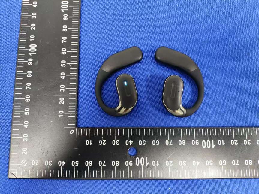
Click to zoom
Application Details
- Equipment Class
- DSS - Part 15 Spread Spectrum Transmitter
- Date of Grant
- Sep 12, 2024
- Application Purpose
- Original Equipment
- Date of Application
- Sep 12, 2024
- Equipment Note
- Sport headphones
- Frequency Range
- 2402.00000000 - 2480.00000000
- Country
- China
Documents & Files
Document Text
Text extracted from the exhibit documents filed with the FCC. Open a document above to read the original.
Users Manual
Product specification The product shall be subject to the physical object, please read the contents of this manual carefully before use. The Company reserves the right to improve the product and its instructions, subject to change without prior notice. Product parameter Pilot lamp On-off key Pilot lampType-c charging BT version: Charging compartment battery: Frequency Response: Model: Endurance time: 9H BT connection instructions BT BT Other Device not connected BT BT my device Connected Other Device Press and hold the power button for 3 seconds Turn on Bluetooth on your phoneConnection successful 1. When the earphones are turned off, long press the power button for 3 seconds to automatically enter pairing mode. 2. Turn on the Bluetooth of the phone, click to search for Bluetooth devices, find "B14", and click to connect. 3. After successful connection, the earphones will sound a voice prompt saying "Connected" Earphone charging case headsetUser Manual Type-C charging cable Basic accessories Key operation guide Press and hold the left and right ear buttons for 3 seconds to turn on the device Press and hold the left and right ear buttons for 5 seconds to turn off the device Power on Shut down Three consecutive clicks on the right ear key to switch between music/game modes Double click on either side to open the key Double click on either side to open the key Long press the left ear key for 1.5 seconds Long press the right ear key for 1.5 seconds Click on the key on the right ear Click on the left ear switch key Four clicks on any earphone Music/Game Mode Music playback Music pause Previous song Next song Volume+ Volume- Sound prompt switching Double click on either side to open the key Double click on either side to open the key Press and hold the key on either side for 1.5 seconds Three consecutive hits on the left ear to activate the key Press the left ear key again for 3 consecutive times to exit Answer the phone Hang up the phone Reject incoming calls Voice wake-up Voice off 6. Click on the key to restore factory settings After 5 consecutive clicks on the left/right earphones, the earphones will shut down (clearing all pairing and connection information) Restore factory settings Clear pairing Tips FCC Statement Note: This equipment has been tested and found to comply with the limits for a Class B digital device, pursuant to part 15 of the FCC Rules. These limits are designed to provide reasonable protection against harmful interference in a residential installation. This equipment generates, uses and can radiate radio frequency energy and, if not installed and used in accordance with the instructions, may cause harmful interference to radio communications. However, there is no guarantee that interference will not occur in a particular installation. If this equipment does cause harmful interference to radio or television reception, which can be determined by turning the equipment off and on, the user is encouraged to try to correct the interference by one or more of the following measures: —Reorient or relocate the receiving antenna. —Increase the separation between the equipment and receiver. —Connect the equipment into an outlet on a circuit different from that to which the receiver is connected. —Consult the dealer or an experienced radio/TV technician for help. This device complies with part 15 of the FCC Rules. Operation is subject to the following two conditions:(1) This device may not cause harmful interference, and (2) this device must accept any interference received, including interference that may cause undesired operation. Any changes or modifications not expressly approved by the party responsible for compliance could void the user's authority to operate the equipment. The device has evaluated to meet general RF exposure requirement. The device can be used be in portable exposure without restriction.
Cover Letter(s)
ShenzhenFanlingTechnologyCo.,Ltd. ModelDifferent Modelname:Sportheadphones FCCID:2BG6U-B14 Modelnumber:B14,B15,KU08 Allmodel’sthefunction,softwareandelectriccircuitarethesame,exceptthecolourandthe modelnumberandcolour. Name:JackZhu Date:2024-09-03 Title:Manager Signatureofapplicant:
External Photos
ExternalPhotos
ID Label/Location Info
Label:
Internal Photos
InternalPhotos BTAnt BTAnt
RF Exposure Info
FCCID:2BG6U-B14 RFExposureEvaluation AccordingtoKDB447498V06andpart2.1093,Unlessspecificallyrequiredbythe publishedRFexposureKDBprocedures,standalone1-gheadorbodyand10-gextremity SARevaluationforgeneralpopulationexposureconditions,bymeasurementornumerical simulation,isnotrequiredwhenthecorrespondingSARTestExclusionThreshold condition(s),listedbelow,is(are)satisfied. For100MHzto6GHzandtestseparationdistances≤50mm,the1-gand10-gSARtest exclusionthresholdsaredeterminedbythefollowing: [(max.powerofchannel,includingtune-uptolerance,mW)/(min.testseparationdistance, mm)]·[√f (GHz) ]≤3.0for1-gSAR,and≤7.5for10-gextremitySAR,where f (GHz) istheRFchanneltransmitfrequencyinGHz PoweranddistanceareroundedtothenearestmWandmmbeforecalculation Theresultisroundedtoonedecimalplaceforcomparison Here, SoaSARtestisnotrequired ModeFreque ncy (MHz) Max Power (dBm) Target power W/ tolerance (dBm) Maxtune uppower tolerance (dBm) Max Power (mW) Min. Distanc e (mm) Calc. threshol ds limit GFSK 2402 -4.172 -3±1-2 0.63105.000.1956 3.0 2441 -3.684-3±1 -20.63105.000.1972 3.0 2480 -3.546-3±1 -20.63105.000.1987 3.0 Π /4-DQ PSK 2402 -3.141 -3 ± 1 -20.63105.000.1956 3.0 2441 -2.677 -3 ± 1 -20.63105.000.1972 3.0 2480 -2.533 -3 ± 1 -20.63105.000.1987 3.0 8DPSK 2402 -2.512 -2±1-1 0.79435.000.2462 3.0 2441 -2.003 -2±1-1 0.79435.000.2482 3.0 2480 -1.806 -2±1-1 0.79435.000.2502 3.0
Test Report
Manufactrer:ShenzhenYongchengInternationalTechnologyCo.,LTD Address:Room611,BuildingF,YuxingScienceandTechnologyIndustrialPark,Baoan District,Shenzhen,Guangdong 2.4GHz2012ChipAntenna:RF201221 _ eturnLoss 1 EvaluationBoardReference PCBDimensionAntennaLayoutReference Unit:mm Unit:mm ElectricalCharacteristics ReturnLoss&Radiation R Trc2dBMag10dB/Ref0dBInvisible1 Trc3dBMag10dB/Ref0dBCalintOffs Frequency S11(dB) (MHz) 2400-10.78 2442-24.81 2484-10.24 S11 M1 M2 2.4000 2.4420 00GHz 00GHz -10.77 -24.81 6dB 2dB 41 31 21 11 0 M32.484000GHz-10.243dB M 1 M3 -9 -19 M2 -29 -39 Ch1Start2GHzPwr0dBmStop3GHz Radiation TF 2.4GHz2012ChipAntenna:RF201221 _ TapingSpecifications ReelandTapingSpecification ReelSpecification TYPESIZEA ψ B ψ C ψ D W ψ M 20127”5K/Reel2.0±0.513.5±1.021±1.060±1.011.5±2.0178±2.0 TappingSpecification PackagingTypeABWEFGHTψDP PaperType32161.90±0.203.50±0.208.0±0.201.75±0.103.5±0.054.0±0.102.0±0.050.75±0.10 +0.10 1.50 -0 4.0±0.1 2.4GHz2012ChipAntenna:RF201221 _ ReliabilityTable TestItemProcedure Requirements CeramicType Remark (Reference) Electrical Characterization Fulfilltheelectrical specification UserSpec. Thermal Shock 1.Preconditioning: 50±10 °C /1hr,thenkeepfor24±1hrsatroomtemp. 2.Initialmeasure:Spec:referInitialspec. 3.Rapidchangeoftemperaturetest: -30 °C to+85 °C ;100cycles; 15minutesatLowercategorytemperature; 15minutesatUppercategorytemperature. NoVisibleDamage. Fulfilltheelectrical specification. MIL-STD-202 107 Temperature Cycling 1.Initialmeasure:Spec:referInitialspec. 2.100Cycles(-30 °C to+85 °C ),SoakMode=1(2Cycle/hours). 3.Measurementat24±2Hoursaftertestcondition. NoVisibleDamage. Fulfilltheelectrical specification. JESD22 JA104 HighTemperature Exposure 1.Initialmeasure:Spec:referInitialspec. 2.Unpowered;500hours@T=+85 °C . 3.Measurementat24±2hoursaftertest. NoVisibleDamage. Fulfilltheelectrical specification. MIL-STD-202 108 LowTemperature Storage 1.Initialmeasure:Spec:referInitialspec. 2.Unpowered:500hours@T=-30 °C . 3.Measurementat24±2hoursaftertest. NoVisibleDamage. Fulfilltheelectrical specification. MIL-STD-202 108 Solderability (SMDBottomSide) Dippingmethod: a.Temperature:235±5°C b.Dippingtime:3±0.5s Thesoldershouldcover over95%ofthecritical areaofbottomside. IEC60384-21/22 4.10 SolderingHeat Resistance (RSH) Preheatingtemperature:150±10°C. Preheatingtime:1~2min. Soldertemperature:260±5°C. Dippingtime:5±0.5s NoVisibleDamage.IEC60384-21/22 4.10 Vibration5g'sfor20min.,12cycleseachof3orientations Note:Use8"X5"PCB.031"thick7securepointson,onelong sideand2securepointsatcornersofoppositesides.Parts mountedwithin2"fromanysecurepoint.Testfrom10-2000 Hz. NoVisibleDamage.MIL-STD-202 Method204 Mechanical Shock Threeshocksineachdirectionshallbeappliedalongthethree mutuallyperpendicularaxesofthetestspecimen(18shocks) Peakvalue:1,500g’s Duration:0.5ms Velocitychange:15.4ft/s Waveform:Half-sine NoVisibleDamage.MIL-STD-202 Method213 Humidity Bias 1.Humidity:85%R.H.,Temperature:85±2°C. 2.Time:500±24hours. 3.Measurementat24±2hrsaftertestcondition. NoVisibleDamage. Fulfilltheelectrical specification. MIL-STD-202 Method106 2.4GHz2012ChipAntenna:RF201221 _ Board Flex (SMD) 1.Mountingmethod: IR-Reflow.PCBSize(L:100×W:40×T:1.6mm) 2.Applytheloadindirectionofthearrowuntilbendingreaches 2mm. NoVisibleDamage.AEC-Q200 005 AdhesionForceof1.8Kgfor60seconds.NoVisibleDamage Magnificationof20Xor greatermaybeemployed forinspectionofthe mechanicalintegrityofthe devicebodyterminalsand body/terminaljunction. AEC-Q200 006 Physical Dimension Anyapplicablemethodusingx10magnification,micrometers, calipers,gauges,contourprojectors,orothermeasuring equipment,capableofdeterminingtheactualspecimen dimensions. Inaccordancewith specification. JESD22 JB100 RevisionHistory RevisionDateContent 12015/8/20Newissue 22017/4/20Updatedetaildimensiononantennalayout 32018/3/1Partnumberandcodingruleupdated
Test Report
Page 1 of 79 Hotline:400-8868-419Fax:86-755-27790922http://www.ncttesting.cn FCCTESTREPORT FCCID:2BG6U-B14 Product:Sportheadphones ModelName:B14,B15,KU08 Brand:N/A ReportNo.:NCT24035637E Preparedfor ShenzhenFanlingTechnologyCo.,Ltd. 3rdFloor,BuildingA4,No.18TongfuRoad,HepingCommunity, FuhaiStreet,Bao'anDistrict,Shenzhen Preparedby ShenzhenNCTTestingTechnologyCo.,Ltd. A101&2FB2,Fuqiao6thArea,XintianCommunity,FuhaiStreet, BaoanDistrict,Shenzhen,People’sRepublicofChina TEL:400-8868-419 FAX:86-755-27790922 ReportNo.:NCT24035637E Page 2 of 79 Hotline:400-8868-419Fax:86-755-27790922http://www.ncttesting.cn 1TESTRESULTCERTIFICATION Applicant’sname: ShenzhenFanlingTechnologyCo.,Ltd. Address: 3rdFloor,BuildingA4,No.18TongfuRoad,HepingCommunity, FuhaiStreet,Bao'anDistrict,Shenzhen Manufacture'sname : ShenzhenFanlingTechnologyCo.,Ltd. Address : 3rdFloor,BuildingA4,No.18TongfuRoad,HepingCommunity, FuhaiStreet,Bao'anDistrict,Shenzhen Productname : Sportheadphones Modelname : B14 Additionalmodel : B15,KU08 Standards :FCCCFR47Part15Section15.247 Testprocedure :ANSIC63.10:2013 TestDate:Aug.20,2024toAug.30,2024 DateofIssue:Aug.30,2024 TestResult :Pass ThisdevicedescribedabovehasbeentestedbyNCT,andthetestresultsshowthatthe equipmentundertest(EUT)isincompliancewiththeFCCrequirements.Anditisapplicable onlytothetestedsampleidentifiedinthereport. Thisreportshallnotbereproducedexceptinfull,withoutthewrittenapprovalofNCT,this documentmaybealteredorrevisedbyNCT,personalonly,andshallbenotedintherevision ofthedocument. TestEngineer: KevenWu/Engineer TechnicalManager: HenryWang/Manager ReportNo.:NCT24035637E Page 3 of 79 Hotline:400-8868-419Fax:86-755-27790922http://www.ncttesting.cn Contents Page 1TESTRESULTCERTIFICATION...............................................................................................................................2 2TESTSUMMARY..........................................................................................................................................................5 3TESTFACILITY.............................................................................................................................................................6 4GENERALINFORMATION..........................................................................................................................................7 4.1GENERALDESCRIPTIONOFE.U.T.....................................................................................................................7 4.2CHANNELLIST.....................................................................................................................................................8 4.3TESTSETUPCONFIGURATION............................................................................................................................9 4.4TESTMODE.........................................................................................................................................................9 5EQUIPMENTDURINGTEST....................................................................................................................................10 5.1EQUIPMENTSLIST.............................................................................................................................................10 5.2MEASUREMENTUNCERTAINTY.........................................................................................................................12 5.3DESCRIPTIONOFSUPPORTUNITS...................................................................................................................12 6CONDUCTEDEMISSION..........................................................................................................................................13 6.1E.U.T.OPERATION............................................................................................................................................13 6.2EUTSETUP.......................................................................................................................................................13 6.3TESTSET-UP(BLOCKDIAGRAMOFCONFIGURATION).................................................................................14 6.4MEASUREMENTPROCEDURE:...........................................................................................................................14 6.5CONDUCTEDEMISSIONLIMIT...........................................................................................................................14 6.6MEASUREMENTDESCRIPTION..........................................................................................................................14 6.7CONDUCTEDEMISSIONTESTRESULT.............................................................................................................14 7RADIATEDSPURIOUSEMISSIONS......................................................................................................................17 7.1EUTOPERATION...............................................................................................................................................17 7.2TESTSETUP......................................................................................................................................................18 7.3SPECTRUMANALYZERSETUP..........................................................................................................................19 7.4TESTPROCEDURE.............................................................................................................................................20 7.5SUMMARYOFTESTRESULTS...........................................................................................................................21 8MAXIMUMPEAKOUTPUTPOWERTEST............................................................................................................38 8.1TESTSTANDARDANDLIMIT.................................................................................................................…
Text truncated - open the document above for the full version.
Test Report
ReportNo.:NCT24035637E Page56of79 Hotline:400-8868-419Fax:86-755-27790922http://www.ncttesting.cn 11NumberofHoppingChannelTest 11.1TestStandardandLimit TestStandard FCCPart15CSection15.247(a)(1) TestLimit >15channels 11.2TestSetup 11.3TestProcedure TheEUTmusthaveitshoppingfunctionenabled.Usingthefollowingspectrumanalyzersetting: 1.Span=thefrequencybandofoperation 2.SettheRBW=100kHz. 3.SettheVBW=300kHz. 4.Sweeptime=autocouple. 5.Detectorfunction=peak. 6.Tracemode=maxhold. 7.Allowtracetofullystabilize. ReportNo.:NCT24035637E Page57of79 Hotline:400-8868-419Fax:86-755-27790922http://www.ncttesting.cn 11.4TestData Mode Frequency (MHz) Packet Type NumofHoppingFrequencies Verdict ANT1Limit GFSKHOPPDH179>=15Pass Pi/4DQPSKHOPP2DH179>=15Pass 8DPSKHOPP3DH179>=15Pass GFSK ReportNo.:NCT24035637E Page58of79 Hotline:400-8868-419Fax:86-755-27790922http://www.ncttesting.cn π/4-DQPSK 8-DPSK ReportNo.:NCT24035637E Page59of79 Hotline:400-8868-419Fax:86-755-27790922http://www.ncttesting.cn 12DwellTimeTest 12.1TestStandardandLimit TestStandardFCCPart15CSection15.247(a)(1) TestLimit 0.4sec 12.2TestSetup 12.3TestProcedure TheEUTmusthaveitshoppingfunctionenabled.Usethefollowingspectrumanalyzersettings: 1.Span=zerospan,centeredonahoppingchannel 2.SettheRBW=1MHz. 3.SettheVBW=1MHz. 4.Sweeptime=asnecessarytocapturetheentiredwelltimeperhoppingchannel. 5.Detectorfunction=peak. 6.Tracemode=maxhold. 7.Allowtracetofullystabilize. ReportNo.:NCT24035637E Page60of79 Hotline:400-8868-419Fax:86-755-27790922http://www.ncttesting.cn 12.4TestData Leftearphone Package Type Pulsewidth (ms) Timeslotlength(ms) Dwelltime (ms) Limit(s)Remark DH10.377timeslotlength*1600/2/79*31.6120.640.4Pass DH31.633timeslotlength*1600/4/79*31.6261.280.4Pass DH52.882timeslotlength*1600/6/79*31.6307.410.4Pass Remark:Allthemodeshavetestedandrecordedtheworstmodeinthereport. TestPlots DH12441MHz ReportNo.:NCT24035637E Page61of79 Hotline:400-8868-419Fax:86-755-27790922http://www.ncttesting.cn DH32441MHz DH52441MHz ReportNo.:NCT24035637E Page62of79 Hotline:400-8868-419Fax:86-755-27790922http://www.ncttesting.cn 13100kHzBandwidthofFrequencyBandEdgeRequirement 13.1TestStandardandLimit TestStandard FCCPart15CSection15.247(d) TestLimit inany100kHzbandwidthoutsidethefrequencybandsinwhichthe spreadspectrumintentionalradiatorinoperating,theradiofrequency powerthatisproducedbytheintentionalradiatorshallbeatleast20dB belowthatinthe100kHzbandwidthwithinthebandthatcontainsthe highestlevelofthedesiredpower,Inaddition,radiatedemissionswhich fallintherestrictedbands,asdefinedin§15.205(a),mustalsocomply withtheradiatedemissionlimitsspecifiedin15.209(a). 13.2TestSetup 13.3TestProcedure TheEUTmusthaveitshopping/Non-hoppingfunctionenabled.Usingthefollowingspectrum analyzersetting: 1.SettheRBW=100kHz. 2.SettheVBW=300kHz. 3.Sweeptime=autocouple. 4.Detectorfunction=peak. 5.Tracemode=maxhold. 6.Allowtracetofullystabilize. ReportNo.:NCT24035637E Page63of79 Hotline:400-8868-419Fax:86-755-27790922http://www.ncttesting.cn 13.4TestData GFSKmode: Lowestchannel ReportNo.:NCT24035637E Page64of79 Hotline:400-8868-419Fax:86-755-27790922http://www.ncttesting.cn Middlechannel ReportNo.:NCT24035637E Page65of79 Hotline:400-8868-419Fax:86-755-27790922http://www.ncttesting.cn Highestchannel ReportNo.:NCT24035637E Page66of79 Hotline:400-8868-419Fax:86-755-27790922http://www.ncttesting.cn π/4-DQPSKmode: Lowestchannel ReportNo.:NCT24035637E Page67of79 Hotline:400-8868-419Fax:86-755-27790922http://www.ncttesting.cn Middlechannel ReportNo.:NCT24035637E Page68of79 Hotline:400-8868-419Fax:86-755-27790922http://www.ncttesting.cn Highestchannel ReportNo.:NCT24035637E Page69of79 Hotline:400-8868-419Fax:86-755-27790922http://www.ncttesting.cn 8-DPSKmode: Lowestchannel ReportNo.:NCT24035637E Page70of79 Hotline:400-8868-419Fax:86-755-27790922http://www.ncttesting.cn Middlechannel ReportNo.:NCT24035637E Page71of79 Hotline:400-8868-419Fax:86-755-27790922http://www.ncttesting.cn Highestchannel ReportNo.:NCT24035637E Page72of79 Hotline:400-8868-419Fax:86-755-27790922http://www.ncttesting.cn GFSKNo-hoppingBandedge-leftside GFSKHoppingBandedge-leftside ReportNo.:NCT24035637E Page73of79 Hotline:400-8868-419Fax:86-755-27790922http://www.ncttesting.cn GFSKNo-hoppingBandedge-rightside GFSKHoppingBandedge-rightside ReportNo.:NCT24035637E Page74of79 Hotline:400-8868-419Fax:86-755-27790922http://www.ncttesting.cn π/4-DQPSKNo-hoppingBandedge-leftside π/4-DQPSKHoppingBandedge-leftside ReportNo.:NCT24035637E Page75of79 Hotline:400-8868-419Fax:86-755-27790922http://www.ncttesting.cn π/4-DQPSKNo-hoppingBandedge-rightside π/4-DQPSKHoppingBandedge-rightside ReportNo.:NCT24035637E Page76of79 Hotline:400-8868-419Fax:86-755-27790922http://www.ncttesting.cn 8-DPSKNo-hoppingBandedge-leftside 8-DPSKHoppingBandedge-leftside ReportNo.:NCT24035637E Page77of79 Hotline:400-8868-419Fax:86-755-27790922http://www.ncttesting.cn 8-DPSKNo-hoppingBandedge-rightside 8-DPSKHoppingBandedge-rightside ReportNo.:NCT24035637E Page78of79 Hotline:400-8868-419Fax:86-755-27790922http://www.ncttesting.cn 14AntennaRequirement 14.1TestStandardandRequirement TestStandard FCCPart15Section15.203/247(c) Requirement 1)15.203requirement: Anintentionalradiatorshallbedesignedtoensurethatnoantennaotherthan thatfurnishedbytheresponsiblepartyshallbeusedwiththedevice.The useofapermanentlyattachedantennaorofanantennathatusesaunique couplingtotheintentionalradiator,themanufacturermaydesigntheunitso thatabrokenantennacanbereplacedbytheuser,buttheuseofastandard antennajackorelectricalconnectorisprohibited. 2)15.247(c)(1)(i)requirement: Systemsoperatinginthe2400-2483.5MHzbandthatisusedexclusivelyfor fixed.Point-to-pointoperationsmayemploytransmittingantennaswith directionalgaingreaterthan6dBiprovidedthemaximumconductedoutput poweroftheintentionalradiatorisreducedby1dBforevery3dBthatthe directionalgainoftheantennaexceeds6dBi. 14.2AntennaConnectedConstruction TheantennaisChipAntennawhichpermanentlyattached,andtheMax.gainoftheantennais 1.06dBi.Itcomplieswiththestandardrequireme…
Text truncated - open the document above for the full version.
Contact Information
Applicant
Jack Zhu(Manager)
Test Firm
SHENZHEN NCT TESTING TECHNOLOGY CO., LTD.Henry Wang
[email protected]0755-27790922
Technical Specifications
| # | Rule Parts | Frequency Range | Power Output |
|---|---|---|---|
| 1 | 15C | 2.40 GHz - 2.48 GHz | 700.00 µW |
Other Applications from Shenzhen Fanling Technology Co., Ltd.
2BG6U-E62
Jul 08, 2024Sport headphones
Equipment Class
DSS - Part 15 Spread Spectrum Transmitter