2BGG6PP12IMU Sensor
PetroPower, LLC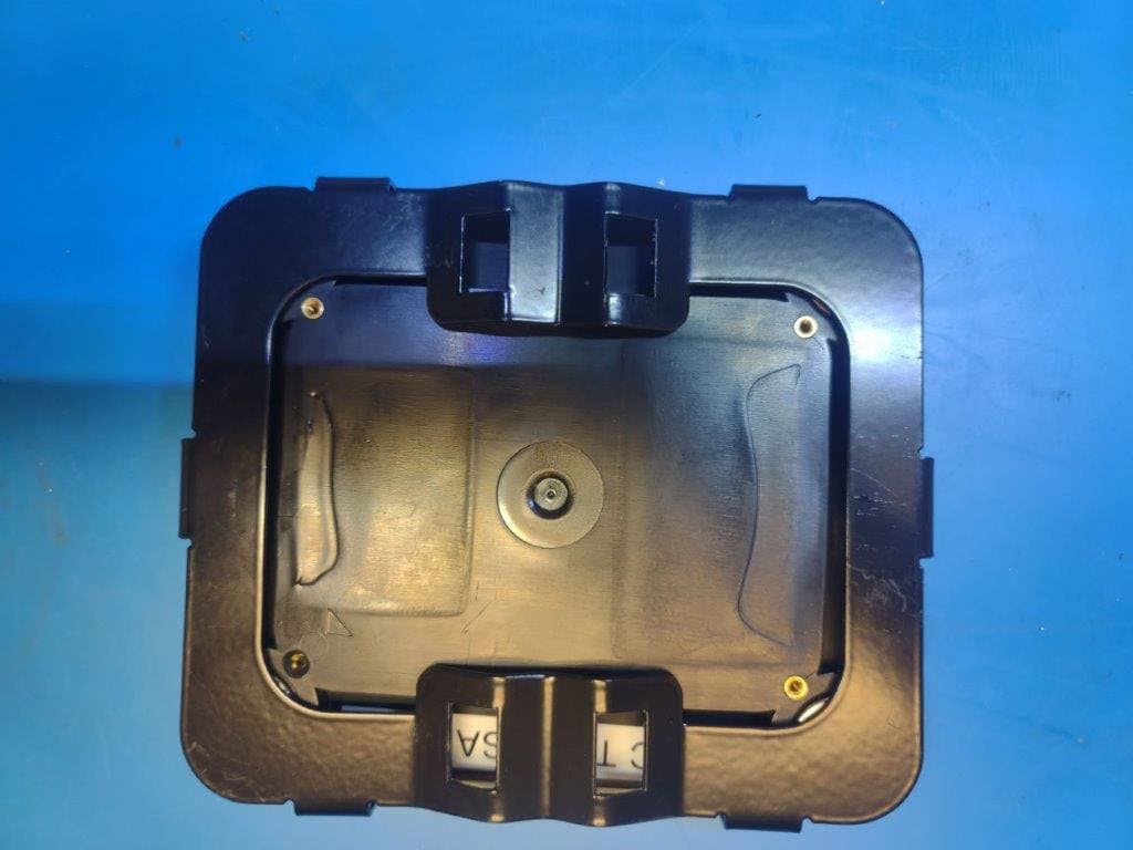
Click to zoom
Application Details
- Equipment Class
- DTS - Digital Transmission System
- Date of Grant
- Jan 22, 2025
- Application Purpose
- Original Equipment
- Equipment Note
- IMU Sensor
- Frequency Range
- 2402.00000000 - 2480.00000000
- Company
- PetroPower, LLC
- Country
- United States
Documents & Files
Document Text
Text extracted from the exhibit documents filed with the FCC. Open a document above to read the original.
Users Manual
IMU Sensor Assembly Product Manual Product Name: IMU Sensor Assembly Model No: 51005 Manufactured by: Petropower LLC 3003 E 37th St N #100 Wichita, KS 67219 This device complies with part 15 of the FCC Rules. Operation is subject to the following two conditions: (1) This device may not cause harmful interference, and (2) this device must accept any interference received, including interference that may cause undesired operation. WARNING: Changes or modifications not expressly approved by PetroPower could void the user’s authority to operate the equipment. Note: This equipment has been tested and found to comply with the limits for a Class A digital device, pursuant to part 15 of the FCC Rules. These limits are designed to provide reasonable protection against harmful interference when the equipment is operated in a commercial environment. This equipment generates, uses, and can radiate radio frequency energy and, if not installed and used in accordance with the instruction manual, may cause harmful interference to radio communications. Operation of this equipment in a residential area is likely to cause harmful interference in which case the user will be required to correct the interference at his own expense. Contact Information Phone: (316) 361-0222 Email: [email protected] Web: https://www.petropower.com/ How to install T-Rex Sensors (drive shaft and polish rod) at the Edge 1. Open T-Rex box, confirm all parts are in place (compare to included manifest in box) 2. Pair each sensor in turn to the T-Rex box by placing the back of the sensor where it is labeled “Pairing” directly against the front of the T- Rex box where it has a corresponding “Pairing” label. a. When placed correctly, the “Pairing” LED light on the front of the T-Rex box should change from blue (ready state) to green (active pairing). b. Wait for the display screen to show a pairing confirmation message. 3. Depending on which device you are pairing, the D.S. (Drive Shaft) or the P.R. (Polish Rod) LED light on the front of the T-Rex box will continue to change colors for 3-5 minutes, so wait patiently if the LED indicator is still changing colors. 4. Repeat for each sensor and once both sensor LEDs display solid green, you are ready for install. 5. Turn off main power to the pump and wait for it to completely stop. 6. Gather the polish rod sensor, the metal bracket it will sit in, and the two hose clamps needed to attach the bracket to the polish rod. What you need before you go to install site: 1. T-Rex V2 Installation Kit (includes 2 T-Rex motion sensors, one polish rod mount, and two hose clamps) 2. Standard tools (flat head screw driver) 3. A ladder Pre-requisite: The T-Rex box must be powered on Example LED 7. Assemble the polish rod sensor clamp: Loop each of the hose clamps through the openings on the bracket as shown here. 8. Attach sensor to bracket: Place the sensor into the bracket so that it is nested neatly between all of the bracket's side tabs. Ensure the arrow on the back side of the sensor is pointing up. 9. Attach the polish rod sensor: Use a ladder to reach the top of the polish rod. Securely attach the sensor+bracket just above the bridle using a 5/16 socket or a flathead screwdriver to tighten the hose clamps. Ensure the arrow on the back side of the sensor is still pointing up and position the front (solar panel) of the sensor so that it is facing the T-Rex control box. 10. Attach the drive shaft sensor: Take the drive shaft sensor and attach it to the side of the rotating drive shaft by pressing the magnetic side of the sensor to the metal surface (solar side should be facing out). Aim to place the sensor as close to the epicenter of the rotating shaft. 11. Remove the ladder and any other materials from the well pump area and turn the main power back on. 12. Call T-Rex Operational Support at (855) 719-2433 - notify them you have completed the sensor install and need to verify the data is coming through for each (drive shaft and polish rod).
External Photos
F2P32069A Page 1 of 6 2024-08-15 PHOTOGRAPHS: EXTERNAL PetroPower, LLC – FCC ID: 2BGG6PP12 Front View Order No(s): F2P32069A Applicant: PetroPower, LLC FCC ID: 2BGG6PP12 F2P32069A Page 2 of 6 2024-08-15 Rear View Order No(s): F2P32069A Applicant: PetroPower, LLC FCC ID: 2BGG6PP12 F2P32069A Page 3 of 6 2024-08-15 Right Side View Order No(s): F2P32069A Applicant: PetroPower, LLC FCC ID: 2BGG6PP12 F2P32069A Page 4 of 6 2024-08-15 Left Side View Order No(s): F2P32069A Applicant: PetroPower, LLC FCC ID: 2BGG6PP12 F2P32069A Page 5 of 6 2024-08-15 Top View Order No(s): F2P32069A Applicant: PetroPower, LLC FCC ID: 2BGG6PP12 F2P32069A Page 6 of 6 2024-08-15 Bottom View
ID Label/Location Info
Sample ID Label and Placement
Internal Photos
F2P32069A Page 1 of 6 2024-08-15 PHOTOGRAPHS: TEST SETUP PetroPower, LLC – FCC ID: 2BGG6PP12 Assembly Order No(s): F2P32069A Applicant: PetroPower, LLC FCC ID: 2BGG6PP12 F2P32069A Page 2 of 6 2024-08-15 BT Antenna Order No(s): F2P32069A Applicant: PetroPower, LLC FCC ID: 2BGG6PP12 F2P32069A Page 3 of 6 2024-08-15 NFC Tag Antenna Order No(s): F2P32069A Applicant: PetroPower, LLC FCC ID: 2BGG6PP12 F2P32069A Page 4 of 6 2024-08-15 PCB Rear View Order No(s): F2P32069A Applicant: PetroPower, LLC FCC ID: 2BGG6PP12 F2P32069A Page 5 of 6 2024-08-15 PCB Top View Order No(s): F2P32069A Applicant: PetroPower, LLC FCC ID: 2BGG6PP12 F2P32069A Page 6 of 6 2024-08-15 Radio IC
RF Exposure Info
20240420 Report Number: F2P32069A-03E Page 1 of 9 Issue Date: 2024-08-15 F2 Labs 16740 Peters Road Middlefield, Ohio 44062 United States of America www.f2labs.com MPE REPORT Manufacturer: PetroPower, LLC 3003 East 37th Street North, Suite 100 Wichita, Kansas 67219 USA Applicant: Same as Above Product Name: T-Rex Solar IMU Sensor Product Description: The product is a solar powered sensor intended to be attached to the surface equipment at an oil well to collect motion data. Operating Voltage/Freq. of EUT During Testing: 3.7VDC Model(s): T-Rex Polished Rod Sensor* *Denotes actual model tested as representative of product family that includes models T-Rex Drive Shaft Sensor and T-Rex Polished Rod Sensor. FCC ID: 2BGG6PP12 Testing Commenced: 2024-07-26 Testing Ended: 2024-08-09 Test Results: In Compliance The EUT complies with the EMC requirements when manufactured identically as the unit tested in this report, including any required modifications. Any changes to the design or build of this unit subsequent to this testing may deem it non- compliant. Standards: • KDB447498 • FCC 1.1310 Order No(s): F2P32069A Applicant: PetroPower, LLC Model: T-Rex Polished Rod Sensor 042216 Report Number: F2P32069A-03E Page 2 of 9 Issue Date: 2024-08-15 Evaluation Conducted by: Julius Chiller, Senior Wireless Project Engineer Report Reviewed by: Ken Littell, Vice President of Operations F2 Labs F2 Labs F2 Labs 26501 Ridge Road 16740 Peters Road 8583 Zionsville Road Damascus, MD 20872 Middlefield, OH 44062 Indianapolis, IN 46268 Ph 301.253.4500 Ph 440.632.5541 Ph 317.610.0611 This test report may be reproduced in full; partial reproduction only may be made with the written consent of F2 Labs. The results in this report apply only to the equipment tested. Order No(s): F2P32069A Applicant: PetroPower, LLC Model: T-Rex Polished Rod Sensor 042216 Report Number: F2P32069A-03E Page 3 of 9 Issue Date: 2024-08-15 TABLE OF CONTENTS 1 ADMINISTRATIVE INFORMATION 2 SUMMARY OF TEST RESULTS/MODIFICATIONS 3 ENGINEERING STATEMENT 4 EUT INFORMATION AND DATA 5 RF EXPOSURE FOR DEVICE >20cm FROM HUMAN FCC Order No(s): F2P32069A Applicant: PetroPower, LLC Model: T-Rex Polished Rod Sensor 042216 Report Number: F2P32069A-03E Page 4 of 9 Issue Date: 2024-08-15 1 ADMINISTRATIVE INFORMATION 1.1 Measurement Location: F2 Labs in Middlefield, Ohio. Site description and attenuation data are on file with the FCC's Sampling and Measurement Branch at the FCC Laboratory in Columbia, MD. 1.2 Measurement Procedure: All measurements were performed according to: • KDB558074 • FCC 15.247 1.4 Document History Document Number Description Issue Date Approved By F2P32069A-03E First Issue 2024-08-15 K. Littell Order No(s): F2P32069A Applicant: PetroPower, LLC Model: T-Rex Polished Rod Sensor 042216 Report Number: F2P32069A-03E Page 5 of 9 Issue Date: 2024-08-15 2 SUMMARY OF TEST RESULTS Test Name Standard(s) Results RF Exposure for Device >20cm from Human KDB447498 FCC 1.1310 Complies Modifications Made to the Equipment RF output power was reduced to 3dBm to meet Spurious Emissions requirements. Order No(s): F2P32069A Applicant: PetroPower, LLC Model: T-Rex Polished Rod Sensor 042216 Report Number: F2P32069A-03E Page 6 of 9 Issue Date: 2024-08-15 3 ENGINEERING STATEMENT This report has been prepared on behalf of PetroPower, LLC to provide documentation for the calculations described herein, based on the measurements taken in supporting Test Reports. This equipment has been tested and calculations were found to comply with KDB447498 and FCC 1.1310. The test results found in this test report relate only to the item(s) tested. Order No(s): F2P32069A Applicant: PetroPower, LLC Model: T-Rex Polished Rod Sensor 042216 Report Number: F2P32069A-03E Page 7 of 9 Issue Date: 2024-08-15 4 EUT INFORMATION AND DATA 4.1 Equipment Under Test: Product: T-Rex Solar IMU Sensor Model(s): T-Rex Polished Rod Sensor* *Denotes actual model tested as representative of product family that includes models T-Rex Drive Shaft Sensor and T-Rex Polished Rod Sensor. Serial No.: None Specified FCC ID: 2BGG6PP12 4.2 Trade Name: PetroPower, LLC 4.3 Power Supply: 3.7 VDC 4.4 Applicable Rules: • KDB447498 • FCC 1.1310 4.5 Antenna: Molex 146153 series balanced antenna, 3.2dBi peak gain. 4.6 Accessories: Device Manufacturer Model Number Serial Number USB to Serial FTDI FTD1232 None Specified DC Supply* BK Precision 1685B 346F17303 Computer* Dell-Latitude T17G 17XZ4Q2 *Indicates F2 Labs-supplied equipment. Order No(s): F2P32069A Applicant: PetroPower, LLC Model: T-Rex Polished Rod Sensor 042216 Report Number: F2P32069A-03E Page 8 of 9 Issue Date: 2024-08-15 4.7 Test Item Condition: The equipment to be tested was received in good condition. 4.8 Testing Algorithm: EUT was set to transmit a continuous modulated signal on the low, mid and high channels in the 2.4 GHz Bluetooth band. Both 1 Mb and 2 Mb data rates were tested. The highest emissions were recorded in the data tables. Order No(s): F2P32069A Applicant: PetroPower, LLC Model: T-Rex Polished Rod Sensor 042216 Report Number: F2P32069A-03E Page 9 of 9 Issue Date: 2024-08-15 5. RF EXPOSURE FOR DEVICE >20cm FROM HUMAN 5.1 Requirements: Distance used is 20cm FCC Limit: 1mW/cm 2 Formula used for result: E.I.R.P. 4 π R2 Results: E.I.R.P. = 3.25mW 3.25mW at the 2402 MHz Low Channel (highest) 3.25mW = 3.25mW = 0.00065mW/cm2 4 π R 2 5026.55
Test Report
Unlicensed Transmitters: Approved Antennas List Manufacturer Antenna Description Type Peak Gain (dBi) Min Cable loss (dB) Ω Connector Type Notes Molex 146153-0050 Flexible adhesive backed PCB antenna Dipole 3.2 NA 50 u.fl 1 Manufacturer Antenna Description Type Length (mm) Width (mm) Other Info Connector Type Notes Molex 1462362111 Rectangular Near Field Communication (NFC) Antenna, with Ferrite Loop 23 27.3 Molex Micro- Lock Plus 2 Notes: 1) Antenna used for compliance testing. 2) RFID passive tag antenna (no active transmit) - - - - - - Documents & Resources Drawings Drawing 1461530050_sd.pdf Packaging Design Drawing 1461530100-000.pdf 3D Models and Design Files 3D Model 1461530050_stp.zip Specifications Application Specification AS-146153-100-001.pdf Product Specification PS-146153-100-001.pdf Product Environment Compliance Compliance Multiple Part Product Compliance Statements Eu RoHS REACH SVHC Low-Halogen Multiple Part Industry Compliance Documents IPC 1752A Class C IPC 1752A Class D Molex Product Compliance Declaration Part Number : 1461530050Product Description : Wi-Fi 6E Flex Cabled Balanced Antenna, 9.00mm Width, 50.00mm Cable Length, Compatible with U.FL / I-PEX MHF Connectors Series Number : 146153Status : Active Product Category : Antennas GADSL/IMDSNot Relevant China RoHS EU ELVNot Relevant Low-Halogen StatusLow-Halogen per IEC 61249-2-21 REACH SVHCNot Contained per D(2023)8585-DC (23 Jan 2024) EU RoHSCompliant per EU 2015/863 - - IEC-62474 chemSHERPA (xml) EU RoHS Certificate of Compliance Part Details General Electrical Physical StatusActive CategoryAntennas Series146153 DescriptionWi-Fi 6E Flex Cabled Balanced Antenna, 9.00mm Width, 50.00mm Cable Length, Compatible with U.FL / I-PEX MHF Connectors Component TypeFlexible Antenna with Cable FunctionSignal Product FamilyInternet of Things (IoT) Antennas: Wi-Fi, Bluetooth, Zigbee Product Name2.4/5GHz Balanced Flex Antenna ProtocolBLE, BT, Thread, Wi-Fi, Wireless Hart, Zigbee TypeInternal, Wi-Fi Antenna UPC889056310000 Band#1 F_End (MHz)2483.5 Band#1 F_Start (MHz)2400 Band#2 F_End (MHz)5930 Band#2 F_Start (MHz)4900 Electrical ConnectivityCable Peak Gain (dBi)3.2 @ 2.4 GHz, 4.25 @ 5 GHz Return Loss - S11 (dB)< -10 Total Efficiency>78% @2.4 GHz, >79% @ 5 GHz Cable Length50.00mm Length34.90mm Mounting StyleAdhesive Mates With / Use With Mates with Part(s) This document was generated on Jun 10, 2024 Net Weight0.380/g Packaging TypePET Film PolarizationLinear Radiation PatternOmnidirectional Thickness0.10mm Width9.00mm DescriptionPart Number 50 Ohms, MCRF, PCB Vertical Jack Receptacle, SMT, 1.25mm Mounted Height 734120110
Test Report
20240202 Report Number: F2P32069A-02E Page 1 of 100 Issue Date: 2024-08-15 F2 Labs 16740 Peters Road Middlefield, Ohio 44062 United States of America www.f2labs.com CERTIFICATION TEST REPORT Manufacturer: PetroPower, LLC 3003 East 37th Street North, Suite 100 Wichita, Kansas 67219 USA Applicant: Same a s Above Product Name: T- Rex Solar IMU Sensor Product Description: The product is a battery/solar powered sensor intended to be attached to the surface equipment at an oil well to collect motion data. Operating Voltage/Freq. of EUT During Testing: 3.7VDC Model(s): T- Rex Polished Rod Sensor* *Denotes actual model tested as representative of product family that includes models T-Rex Drive Shaft Sensor and T-Rex Polished Rod Sensor. FCC ID: 2BGG6PP12 Testing Commenced: 2024-07-26 Testing Ended: 2024-08-09 Summary of Test Results: In Compliance The EUT complies with the EMC requirements when manufactured identically as the unit tested in this report, including any required modifications and/or manufacturer’s statement. Any changes to the design or build of this unit subsequent to this testing may deem it non-compliant. Rules: • FCC Part 15 Subpart C, Section 15.247 • FCC Part 15.31(e) • ANSI C63.10:2013 Order No(s): F2P32069A Applicant: PetroPower, LLC Model: T-Rex Polished Rod Sensor 20240202 Report Number: F2P32069A-02E Page 2 of 100 Issue Date: 2024-08-15 Evaluation Conducted by: Erik Tobin, EMC Engineer Julius Chiller, Senior Wireless Project Engineer Report Reviewed by: Ken Littell, Vice President of Operations F2 Labs F2 Labs F2 Labs 26501 Ridge Road 16740 Peters Road 8583 Zionsville Road Damascus, MD 20872 Middlefield, OH 44062 Indianapolis, IN 46268 Ph 301.253.4500 Ph 440.632.5541 Ph 317.610.0611 This test report may be reproduced in full; partial reproduction only may be made with the written consent of F2 Labs. The results in this report apply only to the equipment tested. Order No(s): F2P32069A Applicant: PetroPower, LLC Model: T-Rex Polished Rod Sensor 20240202 Report Number: F2P32069A-02E Page 3 of 100 Issue Date: 2024-08-15 TABLE OF CONTENTS 1 ADMINISTRATIVE INFORMATION 2 SUMMARY OF TEST RESULTS/MODIFICATIONS 3 TABLE OF MEASURED RESULTS 4 ENGINEERING STATEMENT 5 EUT INFORMATION AND DATA 6 LIST OF MEASUREMENT INSTRUMENTATION 7 OCCUPIED BANDWIDTH 8 CONDUCTED OUTPUT POWER 9 VOLTAGE VARIATIONS 10 CONDUCTED SPURIOUS EMISSIONS 11 RADIATED SPURIOUS EMISSIONS 12 PEAK POWER SPECTRAL DENSITY (PSD) 13 TEST SETUP PHOTOGRAPHS Order No(s): F2P32069A Applicant: PetroPower, LLC Model: T-Rex Polished Rod Sensor 20240202 Report Number: F2P32069A-02E Page 4 of 100 Issue Date: 2024-08-15 1 ADMINISTRATIVE INFORMATION 1.1 Measurement Location: F2 Labs in Middlefield, Ohio. Site description and attenuation data are on file with the FCC's Sampling and Measurement Branch at the FCC Laboratory in Columbia, MD. 1.2 Measurement Procedure: All measurements were performed according to ANSI C63.10 and recommended FCC procedure of measurement under Section 15.247 and in KDB558074. A list of the measurement equipment can be found in Section 6. 1.3 Uncertainty Budget: The uncertainty in EMC measurements arises from several factors which affect the results, some associated with environmental conditions in the measurement room, the test equipment being used and the measurement techniques adopted. The measurement uncertainty budgets detailed below are calculated from the test and calibration data, and are expressed with a 95% confidence factor. Note: Only measurements listed below which relate to tests included in this Test Report are applicable to it. This Uncertainty represents an expanded uncertainty expressed at approximately the 95% confidence level using a coverage factor of k=2. 1.4 Document History Document Number Description Issue Date Approved By F2P32069A-02E First Issue 2024-08-15 K. Littell Measurement Range Expanded Uncertainty Combined Uncertainly Radiated Emissions <1 GHz @ 3m ±5.07dB ±2.54dB Radiated Emissions <1 GHz @10m ±5.09dB ±2.55dB Radiated Emissions 1 GHz to 2.7 GHz ±3.62dB ±1.81dB Radiated Emissions 2.7 GHz to 18 GHz ±3.10dB ±1.55dB AC Power Line Conducted Emissions, 150kHz to 30 MHz ±2.76dB ±1.38dB Order No(s): F2P32069A Applicant: PetroPower, LLC Model: T-Rex Polished Rod Sensor 20240202 Report Number: F2P32069A-02E Page 5 of 100 Issue Date: 2024-08-15 2 SUMMARY OF TEST RESULTS Test Name Standard(s) Results Occupied Bandwidth CFR 47 Part 15.247(a)(2) / KDB558074 Complies Conducted Output Power CFR 47 Part 15.247(b)(2) / KDB558074 Complies Voltage Variations CFR 47 Part 15.31(e) Complies Conducted Spurious Emissions CFR 47 Part 15.247(d) / Part 15.207 / KDB558074 Complies Radiated Spurious Emissions CFR 47 Part 15.247(d) / Part 15.209 / KDB558074 Complies* Peak Power Spectral Density CFR 47 Part 15.247(e) / KDB558074 Complies Frequency Separation ANSI 63.10 2013 (7.8.2) Not Applicable Number of Hopping Frequencies ANSI 63.10 2013 (7.8.3) Not Applicable Dwell Time ANSI 63.10 2013 (7.8.4) Not Applicable Conducted Emissions CFR 47 Part 15.207(a) Not Applicable Modifications Made to the Equipment *RF output power setting was reduced to 3dBm to meet Spurious Emissions requirements. Order No(s): F2P32069A Applicant: PetroPower, LLC Model: T-Rex Polished Rod Sensor 20240202 Report Number: F2P32069A-02E Page 6 of 100 Issue Date: 2024-08-15 3 TABLE OF MEASURED RESULTS 1 Mbps Test Low Channel 2.402 GHz Mid Channel 2.440 GHz High Channel 2.480 GHz Conducted Output Power 1.55mW / 1.91dBm 1.52mW / 1.81dBm 1.49mW / 1.74dBm Conducted Output Power Limit 1 Watt / 30dBm 1 Watt / 30dBm 1 Watt / 30dBm E.I.R.P. 3.24mW / 5.11dBm 3.17mW / 5.01dBm 3.11mW / 4.94dBm E.I.R.P. Limit 4 Watts / 36.02dBm 4 Watts / 36.02dBm 4 Watts / 36.02dBm Peak Power Spectral Density -11.1dBm -11.03dBm -12.10dBm Peak Power Spectral Density Limit 8dBm 8dBm 8dBm -6dB Occupied Bandwidth 0.704 MHz 0.714 MHz 0.728 MHz 99% Occupied Bandwidth 1.07 MHz 1.07 MHz 1.07 MHz Occupied Bandwidth Limit ≥ 500KHz ≥ 500KHz ≥ 500KHz Order No(s): F2P32069…
Text truncated - open the document above for the full version.
Test Setup Photos
F2P32069A Page 1 of 5 2024-08-15 PHOTOGRAPHS: TEST SETUP PetroPower, LLC – FCC ID: 2BGG6PP12 Radiated Spurious Emissions: 0.009 MHz to 30 MHz Order No(s): F2P32069A Applicant: PetroPower, LLC FCC ID: 2BGG6PP12 F2P32069A Page 2 of 5 2024-08-15 Radiated Spurious Emissions: 30 MHz to 1000 MHz Order No(s): F2P32069A Applicant: PetroPower, LLC FCC ID: 2BGG6PP12 F2P32069A Page 3 of 5 2024-08-15 Radiated Spurious Emissions: 1 GHz to 18 GHz Order No(s): F2P32069A Applicant: PetroPower, LLC FCC ID: 2BGG6PP12 F2P32069A Page 4 of 5 2024-08-15 Radiated Spurious Emissions: 18 GHz to 26 GHz Order No(s): F2P32069A Applicant: PetroPower, LLC FCC ID: 2BGG6PP12 F2P32069A Page 5 of 5 2024-08-15 Conducted Output Power, Peak Power Spectral Density, Occupied Bandwidth, Conducted Spurious Emissions and Voltage Variations
Contact Information
Applicant
Spencer Alefs
[email protected]Fax: N/A
Test Firm
F2 LabsWendy Fuster
[email protected]Fax: 301-253-5179
Technical Specifications
| # | Rule Parts | Frequency Range | Power Output |
|---|---|---|---|
| 1 | 15C | 2.40 GHz - 2.48 GHz | 1.56 mW |