2BGRL-T60WIRELESS KARAOKE SPEAKER
Shenzhen Weikang JuLi Intelligent Technology Co., LtdApplication Details
- Equipment Class
- DSS - Part 15 Spread Spectrum Transmitter
- Date of Grant
- Dec 01, 2025
- Application Purpose
- Original Equipment
- Equipment Note
- WIRELESS KARAOKE SPEAKER
- Frequency Range
- 2402.00000000 - 2480.00000000
- Country
- China
Documents & Files
Document Text
Text extracted from the exhibit documents filed with the FCC. Open a document above to read the original.
Attestation Statements
Shenzhen Weikang JuLi Intelligent Technology Co., Ltd 2.911 (d)(5)(i) Equipment Type Attestation v1.2 Section 2.911(d)(5)(i) Certification – EquipmentType Company name: Shenzhen Weikang JuLi Intelligent Technology Co., Ltd Address: Building 22, Building 2202, Xinyuan Villa, Minzhi Community, Minzhi Street, Longhua District, Shenzhen, China Product Name: WIRELESS KARAOKE SPEAKER FCCID: 2BGRL-T60 Model(s):T60 2.911(d)(5)(i) EquipmentType We, [Shenzhen Weikang JuLi Intelligent Technology Co., Ltd] (“the applicant”) certify that the equipment for which authorization is sought through certification is not: Prohibited from receiving an equipment authorization pursuant to § 2.903; of the FCC rules. Identified as an equipment type in the “Covered List” NOTE 1 Yours sincerely, Name: Mai Wei Date: Nov. 20, 2025 Title: manager Company name: Shenzhen Weikang JuLi Intelligent Technology Co., Ltd Signature: NOTE 1 “Covered List ”; is the List of Equipment and Services Covered By Section 2 of The Secure Networks Act, available at https://www.fcc.gov/supplychain/coveredlist References; 1) 986446 D01 Covered Equipment v01 https://apps.fcc.gov/oetcf/kdb/forms/FTSSearchResultPage.cfm?switch=P&id=325672 2) Federal Register document 2022-28263 published on 02/06/23 https://www.federalregister.gov/documents/2023/02/06/2022-28263/protecting-against-national-security-threats-to-the-com munications-supply-chain-through-the
Attestation Statements
Shenzhen Weikang JuLi Intelligent Technology Co., Ltd 2.911 (d)(5)(ii) Applicant Attestation v1.3 Section 2.911(d)(5)(ii) Certification – Applicant (Covered List ) Company name: Shenzhen Weikang JuLi Intelligent Technology Co., Ltd Address: Building 22, Building 2202, Xinyuan Villa, Minzhi Community, Minzhi Street, Longhua District, Shenzhen, China Product Name: WIRELESS KARAOKE SPEAKER FCCID: 2BGRL-T60 Model(s): T60 2.911(d)(5)(ii) Applicant filing We, [Shenzhen Weikang JuLi Intelligent Technology Co., Ltd] (“the applicant”) certify that, as of the date of the filing of the application, the applicant is not identified NOTE 1 on the “Covered List” NOTE 2 , established pursuant to §1.50002 of this chapter, as an entity producing covered communications equipment. Yours sincerely, Name: Mai Wei Date: Nov. 20, 2025 Title: manager Company name: Shenzhen Weikang JuLi Intelligent Technology Co., Ltd Signature: NOTE 1 Delete option not applicable to this application. NOTE 2 “Covered List ”; is the List of Equipment and Services Covered By Section 2 of The Secure Networks Act, available at https://www.fcc.gov/supplychain/coveredlist References; 1) 986446 D01 Covered Equipment v01 https://apps.fcc.gov/oetcf/kdb/forms/FTSSearchResultPage.cfm?switch=P&id=325672 2) Federal Register document 2022-28263 published on 02/06/23 https://www.federalregister.gov/documents/2023/02/06/2022-28263/protecting-against-national-security-threats-to-the-com munications-supply-chain-through-the
Cover Letter(s)
Shenzhen Weikang JuLi Intelligent Technology Co., Ltd Agent Authorization Company: Shenzhen Weikang JuLi Intelligent Technology Co., Ltd Address: Building 22, Building 2202, Xinyuan Villa, Minzhi Community, Minzhi Street, Longhua District, Shenzhen, China Product Name: WIRELESS KARAOKE SPEAKER Model Number(s): T60 Product Description: WIRELESS KARAOKE SPEAKER We authorize MiCOM Labs Inc., 575 Boulder Court, Pleasanton, California 94566, USA, to act on our behalf on all matters concerning the certification of above named equipment. We declare that MiCOM Labs Inc. is allowed to forward all information related to the approval and certification of equipment to the regulatory agencies as required and to discuss any issues concerning the approval application. Any and all acts carried out by MiCOM Labs on our behalf shall have the same effect as acts of our own. Signature: Date: Nov. 20, 2025 Name: Mai Wei Title: manager Company: Shenzhen Weikang JuLi Intelligent Technology Co., Ltd
Cover Letter(s)
Shenzhen Weikang JuLi Intelligent Technology Co., Ltd Office of Engineering Technology Federal Communications Commission 7435 Oakland Mills Road Columbia, MD 21046 USA Date: Nov. 20, 2025 Subject; Request for Confidentiality FCC ID: 2BGRL-T60 To Whom It May Concern, Pursuant to the provisions of the Commission’s rules Title 47 Sections §0.457 and §0.459, we are requesting the Commission to withhold the following attachment(s) as confidential documents from public disclosure indefinitely. These documents contain detailed system and equipment descriptions and are considered as proprietary information in operation of the equipment. The public disclosure of these documents might be harmful to our company and would give competitors an unfair advantage in the market. Schematic Diagram Block Diagram Parts List Operational Description Tune-up Procedure In additional to above mentioned documents, in order to comply with the marketing regulations in Title 47 CFR §2.803 and the importation rules in Title 47 CFR §2.1204, while ensuring that business sensitive information remains confidential until the actual marketing of newly authorized devices, we request Short Term Confidentiality of the following attachment(s); External Photos Test Setup Photos Internal Photos User Manual For 45 days, pursuant to Public Notice DA 04-1705. OR For 180 days pursuantto KDB 726920 D01. It is our understanding that all measurement test reports, FCC ID label format and correspondence during the certification review process cannot be granted as confidential documents and this information will be available for public review once the grant of equipment authorization is issued. Sincerely, Signature: Name: Mai Wei Title: manager
ID Label/Location Info
FCC ID LABEL: Ca. 10mm x 40mm Label Location FCC ID: 2BGRL-T60
RF Exposure Info
FCC RF Exposure EUT Description: WIRELESS KARAOKE SPEAKER Model No.: T60 FCC ID: 2BGRL‐T60 1. Limits According to KDB 447498 D01 General RF Exposure Guidance v06 The 1‐g and 10‐g SAR test exclusion thresholds for 100 MHz to 6 GHz at test separation distances ≤50 mm are determined by: [(max power of channel, including tune‐up tolerance, mW)/(min. test separation distance, mm)]·[√ f(GHz)]≤3.0 for 1‐g SAR and ≤ 7.5 for 10‐g extremity SAR, Where: Result=P/D*√F F= the RF channel transmit frequency in GHz P=Maximum turn‐up power in mw D=Min. test separation distance in mm 2. Test Result of RF Exposure Evaluation Frequency (MHz) Output power (dBm) Tune Up Power (dBm) Max Tune Up power (dBm/mW) Min test separation distance mm Result Limit (mW/cm 2 ) SAR Test Exclusion 2441 0.25 0±1 1/1.26 5 0.393 3.0 Pass Note: PK Output power= conducted power. Conducted power see the test report HK2510245804‐E, antenna gain= 0dBi Per KDB 447498 D01, when the minimum test separation distance is < 5 mm, a distance of 5 mm is applied to determine RF Exposure test exclusion. The test exclusion threshold is 0.393 which is<= 3, RF Exposure testing is not required. Note: Exclusion Thresholds Results=[(max. power of channel, including tune-up tolerance, mW)/(min. test separation distance, mm)] ·[√f (GHz)] f(GHz) is the RF channel transmit frequency in GHz Distance=5mm
Test Report
Antenna testing 1,Hardware testing 2,Software testing 3,Data reading 1,Hardware testing 1.1,PCBA Bare board testing Weld the RF connecting wire to the bare board, and then connect it to the OTA device. The diagram of the RF connecting wire connected to the bare board is shown below: 1.2,Equipment environment The equipment required for this test includes a computer, spectrum analyzer, amplifier, and anechoic chamber, as shown in the figure below: 2,Software Testing 3,D 3.1, 240 0 Data reading 3D radiatio 0MHz: g on pattern off scanning anntenna 2450 250 0 0MHz: 0MHz: 3.2, 3.3, A Scanning an Detailed sca ITEM Model Name Antenna plat MAX.Gain Polarization Impedance model Manufacture Address: Test Enginee ntenna 2D ra an output da e te n e Shen Room Fansh er diation patte ta results nzhen Ruijixin m 520, Buildin hen Commun rn Horiz n Technology ng 4, Yusheng nity, Xin'an St ANT SPEC 2.4G ANT PCB antenna 0dBi zontai and Ve 50Ohm T60 Developmen g Complex, N treet, Bao'an rtical t Co., Ltd o. 98, Ziyou R District, Shen Road, Area 47 nzhen 7, AntennaPhouo&Length(mm)
Test Report
Page 1 of 53 Report No.: HK2510245804-E FCC Test Report Test Report On Behalf of Shenzhen Weikang JuLi Intelligent Technology Co., Ltd For WIRELESS KARAOKE SPEAKER Model No.: T60 FCC ID: 2BGRL-T60 Prepared For: Shenzhen Weikang JuLi Intelligent Technology Co., Ltd Building 22, Building 2202, Xinyuan Villa, Minzhi Community, Minzhi Street, Longhua District, Shenzhen, China Prepared By: Shenzhen HUAK Testing Technology Co., Ltd. 1-2/F., Building B2, Junfeng Zhongcheng Zhizao Innovation Park, Heping, Fuhai Street, Bao’an District, Shenzhen, Guangdong, China Date of Test: Oct. 24, 2025 ~ Oct. 30, 2025 Date of Report: Oct. 30, 2025 Report Number: HK2510245804-E Page 2 of 53 Report No.: HK2510245804-E Test Result Certification Applicant’s Name .................. : Shenzhen Weikang JuLi Intelligent Technology Co., Ltd Address .................................. : Building 22, Building 2202, Xinyuan Villa, Minzhi Community, Minzhi Street, Longhua District, Shenzhen, China Manufacturer's Name ........... : Shenzhen Weikang JuLi Intelligent Technology Co., Ltd Address .................................. : Building 22, Building 2202, Xinyuan Villa, Minzhi Community, Minzhi Street, Longhua District, Shenzhen, China Product Description Trade Mark ............................. : N/A Product Name ......................... : WIRELESS KARAOKE SPEAKER Model and/or Type Reference : T60 Standards .............................. : 47 CFR FCC Part 15 Subpart C 15.247 This publication may be reproduced in whole or in part for non-commercial purposes as long as the Shenzhen HUAK Testing Technology Co., Ltd. is acknowledged as copyright owner and source of the material. Shenzhen HUAK Testing Technology Co., Ltd. takes no responsibility for and will not assume liability for damages resulting from the reader's interpretation of the reproduced material due to its placement and context. Date of Test ............................................ : Date (s) of Performance of Tests ............ : Oct. 24, 2025 ~ Oct. 30, 2025 Date of Issue ........................................... : Oct. 30, 2025 Test Result ............................................... : Pass Testing Engineer Len Liao Technical Manager Sliver Wan Authorized Signatory Jason Zhou Page 3 of 53 Report No.: HK2510245804-E Table of Contents Page 1. Summary ................................................................................................... 5 1.1 Test Standards ............................................................................................................ 5 1.2 Test Description .......................................................................................................... 5 1.3 Information of the Test Laboratory .............................................................................. 6 1.4 Statement of the Measurement Uncertainty ................................................................ 6 2. General Information ................................................................................. 7 2.1 Environmental Conditions ........................................................................................... 7 2.2 General Description of EUT ........................................................................................ 7 2.3 Description of Test Modes and Test Frequency .......................................................... 8 2.4 Equipments Used during the Test ............................................................................... 9 2.5 Related Submittal(s) / Grant (s) ................................................................................ 10 2.6 Modifications ............................................................................................................. 10 2.7 Description of Test Setup .......................................................................................... 10 2.8 Description of Support Units ..................................................................................... 11 3. Test Conditions and Results ................................................................. 12 3.1 AC Conducted Emissions Test .................................................................................. 12 3.2 Radiated Emissions and Band Edge ........................................................................ 15 3.3 Maximum Peak Conducted Output Power ................................................................ 26 3.4 20dB Bandwidth ........................................................................................................ 27 3.5 Frequency Separation .............................................................................................. 31 3.6 Number of Hopping Frequency ................................................................................. 33 3.7 Time of Occupancy (Dwell Time) .............................................................................. 35 3.8 Out-of-Band Emissions ............................................................................................. 39 3.9 Pseudorandom Frequency Hopping Sequence ........................................................ 49 3.10 Antenna Requirement ........................................................................................... 50 4. Test Setup Photos of the EUT ............................................................... 51 5. Photos of the EUT .................................................................................. 53 Page 4 of 53 Report No.: HK2510245804-E ** Modified History ** Revision Description Issued Date Remark Revision 1.0 Initial Test Report Release Oct. 30, 2025 Jason Zhou Page 5 of 53 Report No.: HK2510245804-E 1. Summary 1.1 Test Standards The tests were performed according to following standards: FCC Rules Part 15.247: Frequency Hopping, Direct Spread Spectrum and Hybrid Systems that are in operation within the bands of 902-928 MHz, 2400-2483.5 MHz, and 5725-5850 MHz ANSI C63.10: 2020: American National Standard for Te…
Text truncated - open the document above for the full version.
Test Report
Page 39 of 53 Report No.: HK2510245804-E 3.8 Out-of-Band Emissions Limit In any 100 kHz bandwidth outside the frequency band in which the spread spectrum or digitally modulated intentional radiator is operating, the radio frequency power that is produced by the intentional radiator shall be at least 20 dB below that in the 100 kHz bandwidth within the band that contains the highest level of the desired power, based on either an RF con-ducted or a radiated measurement, pro-vided the transmitter demonstrates compliance with the peak conducted power limits. If the transmitter com-plies with the conducted power limits based on the use of RMS averaging over a time interval, as permitted under paragraph (b)(3) of this section, the attenuation required under this paragraph shall be 30 dB instead of 20 dB. Attenuation below the general limits specified in §15.209(a) is not required. Test Procedure Connect the transmitter output to spectrum analyzer using a low loss RF cable, and set the spectrum analyzer to RBW=100 kHz, VBW= 300 kHz, peak detector , and max hold. Measurements utilizing these setting are made of the in-band reference level, band edge and out-of-band emissions. Test Configuration EUT SPECTRUM ANALYZER Test Results Remark: The measurement frequency range is from 30MHz to the 10th harmonic of the fundamental frequency. The lowest, middle and highest channels are tested to verify the spurious emissions and bandage measurement data. We measured all conditions (DH1, DH3, DH5) and recorded worst case at DH5 and 3DH5 Test plot as follows: Page 40 of 53 Report No.: HK2510245804-E GFSK CH00 CH39 Page 41 of 53 Report No.: HK2510245804-E CH78 Page 42 of 53 Report No.: HK2510245804-E Left Band edge hoping off Right Band edge hoping off Left Band edge hoping on Right Band edge hoping on Page 43 of 53 Report No.: HK2510245804-E π/4DQPSK CH00 CH39 Page 44 of 53 Report No.: HK2510245804-E CH78 Page 45 of 53 Report No.: HK2510245804-E Left Band edge hoping off Right Band edge hoping off Left Band edge hoping on Right Band edge hoping on Page 46 of 53 Report No.: HK2510245804-E 8DPSK CH00 CH39 Page 47 of 53 Report No.: HK2510245804-E CH78 Page 48 of 53 Report No.: HK2510245804-E Left Band edge hoping off Right Band edge hoping off Left Band edge hoping on Right Band edge hoping on Page 49 of 53 Report No.: HK2510245804-E 3.9 Pseudorandom Frequency Hopping Sequence Test Applicable For 47 CFR Part 15C section 15.247 (a) (1): Frequency hopping systems shall have hopping channel carrier frequencies separated by a minimum of 25 kHz or the 20 dB bandwidth of the hop-ping channel, whichever is greater. Alternatively, frequency hopping systems operating in the 2400–2483.5 MHz band may have hopping channel carrier frequencies that are separated by 25 kHz or two-thirds of the 20 dB bandwidth of the hopping channel, whichever is greater, provided the systems operate with an output power no greater than 125 mW. The system shall hop to channel frequencies that are selected at the system hopping rate from a pseudo randomly ordered list of hopping frequencies. Each frequency must be used equally on the average by each transmitter. The system receivers shall have input bandwidths that match the hop-ping channel bandwidths of their corresponding transmitters and shall shift frequencies in synchronization with the transmitted signals. EUT Pseudorandom Frequency Hopping Sequence Requirement The pseudorandom frequency hopping sequence may be generated in a nice-stage shift register whose 5 th and 9 th stage outputs are added in a modulo-two addition stage. And the result is fed back to the input of the first stage. The sequence begins with the first one of 9 consecutive ones, for example: the shift register is initialized with nine ones. ● Number of shift register stages:9 ● Length of pseudo-random sequence:2 9 -1=511 bits ● Longest sequence of zeros:8(non-inverted signal) An example of pseudorandom frequency hopping sequence as follows: Each frequency used equally one the average by each transmitter. The system receiver have input bandwidths that match the hopping channel bandwidths of their corresponding transmitter and shift frequencies in synchronization with the transmitted signals. Page 50 of 53 Report No.: HK2510245804-E 3.10 Antenna Requirement Standard Applicable For intentional device, according to FCC 47 CFR Section 15.203, an intentional radiator shall be designed to ensure that no antenna other than that furnished by the responsible party shall be used with the device. And according to FCC 47 CFR Section 15.247, if transmitting antennas of directional gain greater than 6dBi are used, the power shall be reduced by the amount in dB that the directional gain of the antenna exceeds 6dBi. Refer to Statement Below for Compliance. The manufacturer may design the unit so that the user can replace a broken antenna, but the use of a standard antenna jack or electrical connector is prohibited. Further, this requirement does not apply to intentional radiators that must be professionally installed. Antenna Connected Construction The antenna used in this product is a PCB Antenna, is a permanently attached antenna on the PCB. It conforms to the standard requirements. The directional gains of antenna used for transmitting is 0dBi. Antenna Page 51 of 53 Report No.: HK2510245804-E 4. Test Setup Photos of the EUT Radiated Emission Page 52 of 53 Report No.: HK2510245804-E AC Conducted Emission RF Conducted Emission Page 53 of 53 Report No.: HK2510245804-E 5. Photos of the EUT Reference to the report: ANNEX A of External photos and ANNEX B of Internal photos ---------End of test report---------
Test Setup Photos
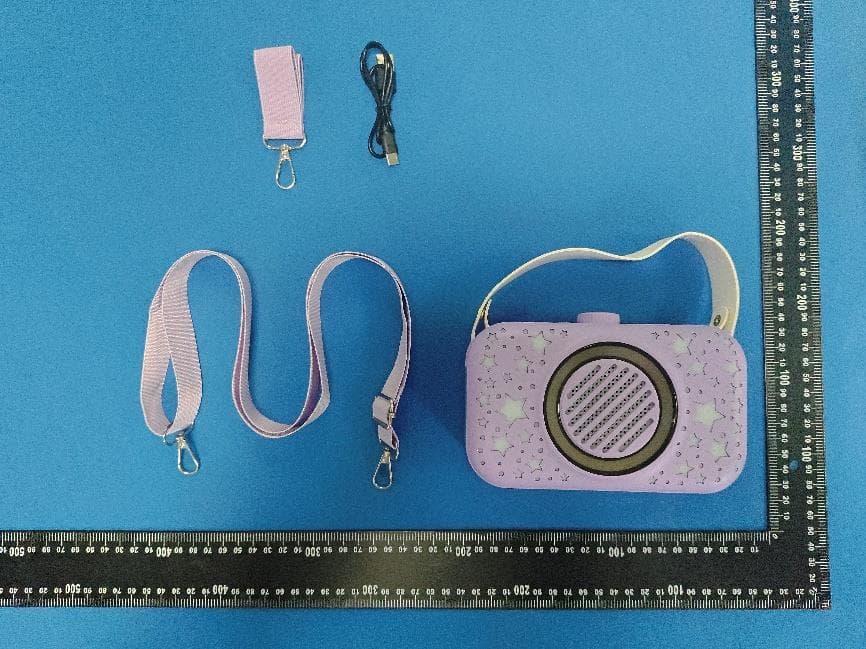
Test Model: T60 Radiated Emission AC Conducted Emission RF Conducted Emission
Contact Information
Applicant
Mai Wei(manager)
[email protected]Fax: 13827356068
Test Firm
Shenzhen HUAK Testing Technology Co., Ltd.Jason Zhou
Technical Specifications
| # | Rule Parts | Frequency Range | Power Output |
|---|---|---|---|
| 1 | 15C | 2.40 GHz - 2.48 GHz | 1.06 mW |
Other Applications from Shenzhen Weikang JuLi Intelligent Technology Co., Ltd
2BGRL-T05
Jul 15, 2026WIRELESS KARAOKE SPEAKER
Equipment Class
DSS - Part 15 Spread Spectrum Transmitter2BGRL-T09
Dec 04, 2025WIRELESS KARAOKE SPEAKER
Equipment Class
DSS - Part 15 Spread Spectrum Transmitter2BGRL-T50
Dec 01, 2025WIRELESS KARAOKE SPEAKER
Equipment Class
DSS - Part 15 Spread Spectrum Transmitter2BGRL-U8
Sep 29, 2025WIRELESS KARAOKE SPEAKER
Equipment Class
DSS - Part 15 Spread Spectrum Transmitter2BGRL-T06
Sep 29, 2025WIRELESS KARAOKE SPEAKER
Equipment Class
DSS - Part 15 Spread Spectrum Transmitter