2BGSP-NWP2Nocturnal epilepsy seizure detection and monitoring device
LivAssured B.V.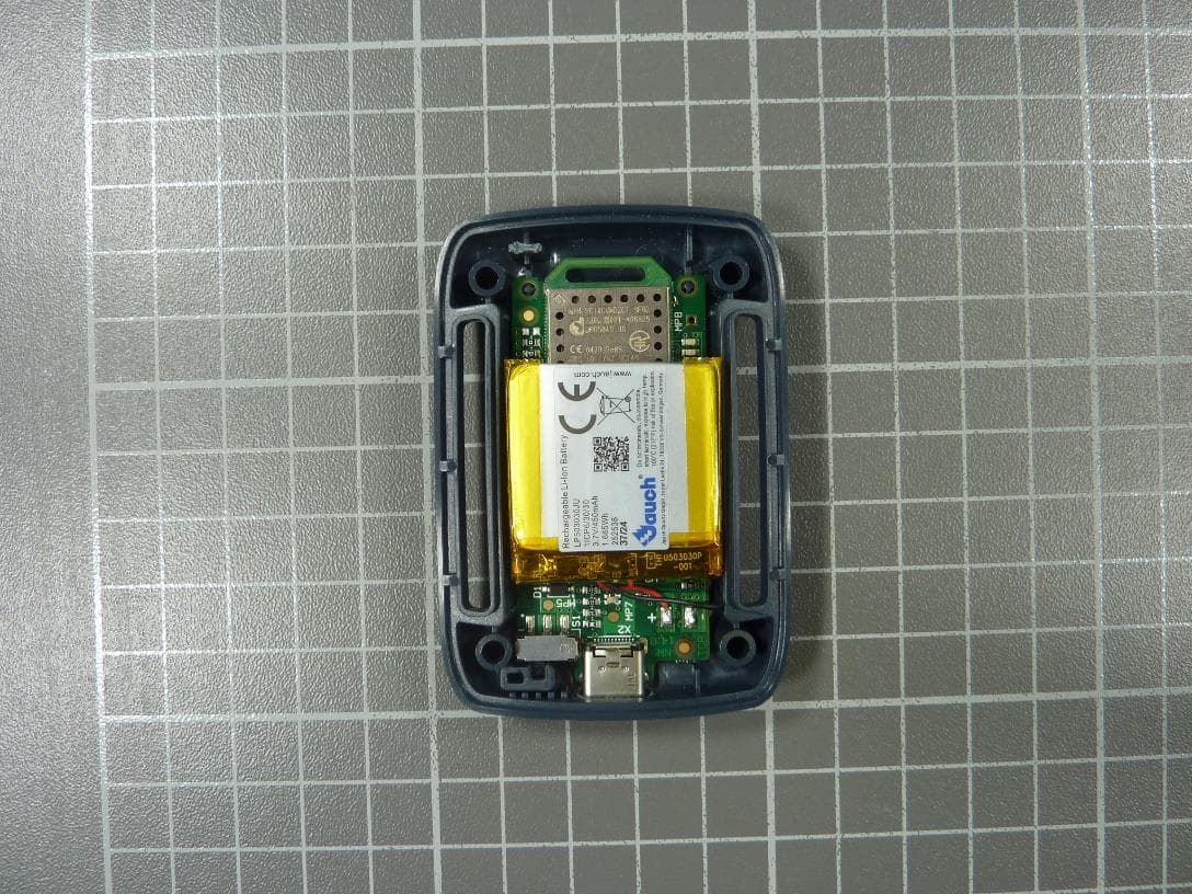
Click to zoom
Application Details
- Equipment Class
- PUT - Part 15 Unlicensed PCS portable Tx worn on body
- Date of Grant
- Feb 03, 2026
- Application Purpose
- Original Equipment
- Equipment Note
- Nocturnal epilepsy seizure detection and monitoring device
- Frequency Range
- 1921.53600000 - 1928.44800000
- Company
- LivAssured B.V.
- Country
- Netherlands
Documents & Files
Document Text
Text extracted from the exhibit documents filed with the FCC. Open a document above to read the original.
Users Manual
Manual version 1.3 1 EN EN User manual United States Manual version 1.3 3 EN Legal Manufacturer LivAssured B.V. Schipholweg 103 2316 XC, Leiden The Netherlands Support: +3185 0601252 M: [email protected] www.nightwatchepilepsy.com © 2024 LivAssured, all rights reserved. No part of this manual may be reproduced in any form without the written permission of LivAssured. LivAssured reserves the right to change or improve its products and any accompanying technical literature without specific notice of the changes or improvements. User Manual United States, Version 1.3 Date of issue: DRAFT EN Contents 1 General .................................................................................................................................... 7 1.1 About this user manual ................................................................................................. 7 1.2 Explanation of symbols used ........................................................................................ 7 1.3 General warnings and cautions .................................................................................... 9 2 NightWatch+ ......................................................................................................................... 10 2.1 Indication for use ......................................................................................................... 10 2.2 Type of seizures NightWatch+ detects....................................................................... 10 2.3 Operation mode .......................................................................................................... 11 2.4 User profile .................................................................................................................. 11 2.5 Possible side effects .................................................................................................... 12 2.6 Clinical performance & benefits ................................................................................. 12 2.7 NightWatch+ package contents .................................................................................. 14 3 The different components and how they work ................................................................. 16 3.1 Sensor with elastic strap ............................................................................................. 16 3.2 Comfort Patch .............................................................................................................. 17 3.3 Alarm station ................................................................................................................ 19 4 Using your NightWatch+ ...................................................................................................... 20 4.1 Preparing for first use ................................................................................................. 20 4.2 Daily use ....................................................................................................................... 25 4.3 Managing alarm sounds ............................................................................................. 28 4.4 Charging the sensor .................................................................................................... 28 4.5 Maintenance & cleaning.............................................................................................. 29 4.6 Reuse ............................................................................................................................ 30 4.7 Transport or storage ................................................................................................... 30 5 Signals from the sensor and the alarm station ................................................................. 30 5.1 Alarm signals ................................................................................................................ 31 5.2 Information signals ...................................................................................................... 32 5.3 Responding to alarms ................................................................................................. 33 6 Seizure monitoring ............................................................................................................... 35 6.1 The Online Portal ......................................................................................................... 35 6.2 How to connect to the Online Portal ......................................................................... 36 6.3 Getting started using the Online Portal ..................................................................... 36 6.4 What’s there to view? .................................................................................................. 37 Manual version 1.3 5 EN 6.5 Does the NightWatch+ Portal respect my privacy? ................................................... 42 6.6 Integration of NightWatch+ with other devices ........................................................ 42 7 Technical specifications ....................................................................................................... 43 7.1 Specifications NightWatch+ ........................................................................................ 43 7.2 Environmental conditions ........................................................................................... 43 7.3 Electromagnetic environment conditions ................................................................. 44 7.4 Cybersecurity ............................................................................................................... 47 8 Regulatory and Compliance ................................................................................................ 48 8.1 Laboratory testing ....................................................................................................... 48 8.2 FCC compliance .........................…
Text truncated - open the document above for the full version.
Attestation Statements
LivAssured BV Schipholweg 103 2316 XC, Leiden The Netherlands PHONE: +31 85 0601252 COC: 57815771 VAT: NL852748450B01 IBAN: NL10RABO0129507873 LivAssured B.V. Schipholweg 103, 2316XC, Leiden Netherlands Federal Communication Commission Authorization and Evaluation Division 7435 Oakland Mills Road Columbia, MD 21046 USA 9 th of July, 2024 Attestation Statement according to 2.911(d)(5)(i) and 2.911(d)(5)(ii) FCC ID: 2BGSP-NWP2 TO WHOM IT MAY CONCERN: Hereby we certify that the equipment for which authorization is sought is not “covered” equipment prohibited from receiving an equipment authorization pursuant to section 2.903 of the FCC rules. Further we certify that, as of the date of the filing of the application, LivAssured B.V. is not identified on the Covered List as an entity producing “covered” equipment. Sincerely, _______________ LivAssured B.V. FRN 0035509199 Schipholweg 103 2316XC, Leiden Netherlands Tim Herrebrugh +31850601252
Attestation Statements
LivAssured BV Schipholweg 103 2316 XC, Leiden The Netherlands PHONE: +31 85 0601252 COC: 57815771 VAT: NL852748450B01 IBAN: NL10RABO0129507873 LivAssured B.V. Schipholweg 103, 2316XC, Leiden Netherlands Federal Communication Commission Authorization and Evaluation Division 7435 Oakland Mills Road Columbia, MD 21046 USA 15 th of August, 2024 Attestation Statement according to 2.911(d)(7) FCC ID: 2BGSP-NWP2 TO WHOM IT MAY CONCERN: We, LivAssured B.V. designate Taronga Technology Inc, to act as U.S. agent for service of process. Taronga Technology Inc hereby acknowledges the obligation of the U.S. agent for service of process. Further LivAssured B.V. accepts to maintain an agent for no less than one year after the grantee has terminated all marketing and importation or the conclusion of any Commission-related proceeding involving the equipment. Sincerely _______________ LivAssured B.V. FRN 0035509199 Schipholweg 103 2316XC, Leiden Netherlands Tim Herrebrugh +31850601252 [email protected] _______________ Taronga Technology Inc FRN 0035640499 1253 Highway A1A Satellite Beach, FL 32937 Johannes Steensma +1-321-543-2167 [email protected]
Cover Letter(s)
Document Version 1.1 2020-10-30 LONG-TERM CONFIDENTIALITY REQUEST for Certification Service in the USA Federal Communication Commission Equipment Authorization Division, Application Processing Branch 7435 Oakland Mills Road Columbia, MD 21048 TO WHOM IT M AY CONCERN Pursuant to Paragraphs §0.457 and 0.459 of the Commission’s Rules (47 C.F.R.) and Section §552(b)(4) of the Freedom of Information Act, we request Long-Term Confidentiality for the following product: For the product stated above, we request Long-Term Confidentiality for exhibits which contain Block Diagram, Operational Description, Parts List/Tune Up Info, Schematics, SDR Software/Security Info. The above exhibits contain ou r trade secrets and proprietary information that could be of benefit to o ur competitors. This information will not be publicly available. If you have any questions, please feel free to contact us at the address shown below. Sincerely, Company Name: Phone: Company Address: Fax: E-mail: Contact Name: Signature: Signature Date: Check your GC here. Click Grantee Search. FCC I D: Grantee Code Equipment Product Code
External Photos
2026-01-29 Page 1 of 4 Annex A: Ph ot ogr aphs o f the T est S et-up Photo 1: Radiated Emission Photo 2: Radiated Emission Test report no.: 1-6175/23-04-02-TR01-R00 2026-01-29 Page 2 of 4 Annex B : Exte rnal Pho tog rap hs o f t he EUT Photo 1: Photo 2: Test report no.: 1-6175/23-04-02-TR01-R00 2026-01-29 Page 3 of 4 Annex C : In ter nal Pho tog raphs o f t h e EUT Photo 1: Photo 2: Test report no.: 1-6175/23-04-02-TR01-R00 2026-01-29 Page 4 of 4 Photo 3: Photo 4:
Internal Photos
2026-01-29 Page 1 of 4 Annex A: Ph ot ogr aphs o f the T est S et-up Photo 1: Radiated Emission Photo 2: Radiated Emission Test report no.: 1-6175/23-04-02-TR01-R00 2026-01-29 Page 2 of 4 Annex B : Exte rnal Pho tog rap hs o f t he EUT Photo 1: Photo 2: Test report no.: 1-6175/23-04-02-TR01-R00 2026-01-29 Page 3 of 4 Annex C : In ter nal Pho tog raphs o f t h e EUT Photo 1: Photo 2: Test report no.: 1-6175/23-04-02-TR01-R00 2026-01-29 Page 4 of 4 Photo 3: Photo 4:
RF Exposure Info
© cetecom advanced GmbH Page 1 of 33 BNetzA - CAB - 02/21 - 102 TEST REPORT Test Report No.: 1-6175-23-02-04_TR1-R01 Testing Laboratory Applicant cetecom advanced GmbH Untertuerkheimer Strasse 6 – 10 66117 Saarbruecken / Germany Phone: + 49 681 5 98 - 0 Fax: + 49 681 5 98 - 9075 Internet: https://cetecomadvanced.com e-mail: [email protected] Accredited Testing Laboratory: The testing laboratory (area of testing) is accredited according to DIN EN ISO/IEC 17025 (2018-03) by the Deutsche Akkreditierungsstelle GmbH (DAkkS). The accreditation is valid for the scope of testing procedures as stated in the accreditation certificate with the registration number: D-PL-12047-01-00. ISED Testing Laboratory Recognized Listing Number: DE0001 FCC designation number: DE0002 SIQ Ljubljana Mašera - Spasiceva ulica 10 SI-1000 Ljubljana/SLOVENIA Contact: Andrej Škof e-mail: [email protected] Phone: +386 1 4778 154 Manufacturer LivAssured BV Schipholweg 103 2316 XC Leiden/NETHERLANDS Test Standards IEC/IEEE 62209-1528-2020 Measurement procedure for the assessment of specific absorption rate of human exposure to radio frequency fields from hand-held and body-mounted wireless communication devices – Part 1528: Human models, instrumentation, and procedures (Frequency range of 4 MHz to 10 GHz) For further applied test standards please refer to section 3 of this test report. Test Item Kind of test item: Seizure Detection Device Device type: Limb worn device Model name: NightWatch + US Sensor S/N serial number: 24170005 FCC-ID: 2BGSP-NWP2 Hardware Version Identification No. (HVIN): V1.0 Hardware status: V1.0 Software status: V2.2.0 Frequency: UPCS 1925 MHz Antenna: integrated antenna Power supply: AC/DC adapter, 5V DC Test sample status: identical prototype Exposure category: general population / uncontrolled environment This test report is electronically signed and valid without handwritten signature. For verification of the electronic signatures, the public keys can be requested at the testing laboratory. Test Report authorised: Test performed: Alexander Hnatovskiy Marco Scigliano Lab Manager Testing Manager Radio Labs Radio Labs Test report no.: 1-6175-23-02-04_TR1-R01 © cetecom advanced GmbH Page 2 of 33 1 Table of contents 1 Table of contents ............................................................................................................................................ 2 2 General information ....................................................................................................................................... 3 2.1 Notes and disclaimer .......................................................................................................................... 3 2.2 Application details ............................................................................................................................... 3 2.3 Statement of compliance .................................................................................................................... 3 2.4 Technical details .................................................................................................................................. 4 3 Test standards/ procedures references ....................................................................................................... 5 3.1 RF exposure limits .............................................................................................................................. 6 4 Reporting statements of conformity – decision rule .................................................................................. 7 5 Summary of Measurement Results .............................................................................................................. 7 6 Test Environment ........................................................................................................................................... 8 7 Test Set-up ...................................................................................................................................................... 9 7.1 Measurement system .......................................................................................................................... 9 7.1.1 System Description ..................................................................................................................... 9 7.1.2 Test environment ...................................................................................................................... 10 7.1.3 Probe description ...................................................................................................................... 10 7.1.4 Phantom description ................................................................................................................. 11 7.1.5 Device holder description ......................................................................................................... 12 7.1.6 Scanning procedure .................................................................................................................. 13 7.1.7 Comparison of DASY 52 NEO and cDASY6/DASY8 ............................................................... 17 7.1.8 Spatial Peak SAR Evaluation ................................................................................................... 18 7.1.9 Data Storage and Evaluation .................................................................................................... 21 7.1.10 Tissue simulating liquids: dielectric properties ......................................................................... 23 7.1.11 Tissue simulating liquids: parameters ...................................................................................... 23 7.1.12 Measurement uncertainty evaluation for SAR test ................................................................... 24 7.1.13 Measurement uncertainty evaluation for System Check .........................................................…
Text truncated - open the document above for the full version.
RF Exposure Info
Page 1 of 5 Annex C Photo documentation Appendix No.: 1-6175-23-02-04_TR1-A101-R01 Testing Laboratory cetecom advanced GmbH Untertuerkheimer Strasse 6 – 10 66117 Saarbruecken/Germany Phone: + 49 681 5 98 - 0 Fax: + 49 681 5 98 - 9075 Internet: https://www.cetecomadvanced.com e-mail: [email protected] Accredited Test Laboratory: The testing laboratory (area of testing) is accredited according to DIN EN ISO/IEC 17025 (2018-03) by the Deutsche Akkreditierungsstelle GmbH (DAkkS) The accreditation is valid for the scope of testing procedures as stated in the accreditation certificate starting with the registration number: D-PL-12047-01-00. Appendix no.: 1-6175-23-02-04_TR1-A101-R01 Page 2 of 5 Photo 1: Measurement System DASY Photo 2: EUT - Front side view Appendix no.: 1-6175-23-02-04_TR1-A101-R01 Page 3 of 5 Photo 3: EUT - Side view Photo 4: EUT - Back side view Appendix no.: 1-6175-23-02-04_TR1-A101-R01 Page 4 of 5 Photo 5: EUT - Front side view (Label) Appendix no.: 1-6175-23-02-04_TR1-A101-R01 Page 5 of 5 Photo 6: Test position - back with 0mm distance Photo 7: Test position - back with 0mm distance
RF Exposure Info
Page 1 of 32 Annex D Appendix No.: 1-6175-23-02-04_TR1-A201-R01 Testing Laboratory cetecom advanced GmbH Untertuerkheimer Strasse 6 – 10 66117 Saarbruecken/Germany Phone: + 49 681 5 98 - 0 Fax: + 49 681 5 98 - 9075 Internet: https://www.cetecomadvanced.com e-mail: [email protected] Accredited Test Laboratory: The testing laboratory (area of testing) is accredited according to DIN EN ISO/IEC 17025 (2018-03) by the Deutsche Akkreditierungsstelle GmbH (DAkkS) The accreditation is valid for the scope of testing procedures as stated in the accreditation certificate starting with the registration number: D-PL-12047-01-00. Appendix with Calibration data, Phantom certificate and system check information 2012-01-16 Appendix no.: 1-6175-23-02-04_TR1-A201-R01 Page 2 of 32 1 Table of contents 1 Table of contents ....................................................................................................................................... 2 2 Calibration report “Probe EX3DV4” – SN: 7635 ..................................................................................... 3 3 Calibration report “1900 MHz System validation dipole” .................................................................... 13 4 Calibration certificate of Data Acquisition Unit (DAE4ip) – SN: 1842 ................................................ 22 5 Certificate of “SAM Twin Phantom V4.0, V5.0, V8.0’’ .......................................................................... 23 6 Certificate of “ELI Phantom V8.0’’ ......................................................................................................... 25 7 Application Note System Performance Check ..................................................................................... 26 7.1 Purpose of system performance check ..................................................................................... 26 7.2 System Performance check procedure ...................................................................................... 26 7.3 Uncertainty Budget ...................................................................................................................... 27 7.4 Power set-up for validation ......................................................................................................... 31 7.5 Laboratory reflection ................................................................................................................... 32 7.6 Additional system checks ........................................................................................................... 32 Appendix no.: 1-6175-23-02-04_TR1-A201-R01 Page 3 of 32 2 Calibration report “Probe EX3DV4” – SN: 7635 Appendix no.: 1-6175-23-02-04_TR1-A201-R01 Page 4 of 32 Appendix no.: 1-6175-23-02-04_TR1-A201-R01 Page 5 of 32 Appendix no.: 1-6175-23-02-04_TR1-A201-R01 Page 6 of 32 Appendix no.: 1-6175-23-02-04_TR1-A201-R01 Page 7 of 32 Appendix no.: 1-6175-23-02-04_TR1-A201-R01 Page 8 of 32 Appendix no.: 1-6175-23-02-04_TR1-A201-R01 Page 9 of 32 Appendix no.: 1-6175-23-02-04_TR1-A201-R01 Page 10 of 32 Appendix no.: 1-6175-23-02-04_TR1-A201-R01 Page 11 of 32 Appendix no.: 1-6175-23-02-04_TR1-A201-R01 Page 12 of 32 Appendix no.: 1-6175-23-02-04_TR1-A201-R01 Page 13 of 32 3 Calibration report “1900 MHz System validation dipole” Appendix no.: 1-6175-23-02-04_TR1-A201-R01 Page 14 of 32 Appendix no.: 1-6175-23-02-04_TR1-A201-R01 Page 15 of 32 Appendix no.: 1-6175-23-02-04_TR1-A201-R01 Page 16 of 32 Appendix no.: 1-6175-23-02-04_TR1-A201-R01 Page 17 of 32 Appendix no.: 1-6175-23-02-04_TR1-A201-R01 Page 18 of 32 Appendix no.: 1-6175-23-02-04_TR1-A201-R01 Page 19 of 32 Antenna Parameters with Head TSL From cal. data Measured 2024-06-21 Impedance; transformed to feed point 51.8Ω +3.4jΩ 52.3Ω +3.8jΩ Return Loss -28.5dB -27.4dB Appendix no.: 1-6175-23-02-04_TR1-A201-R01 Page 20 of 32 Appendix no.: 1-6175-23-02-04_TR1-A201-R01 Page 21 of 32 Appendix no.: 1-6175-23-02-04_TR1-A201-R01 Page 22 of 32 4 Calibration certificate of Data Acquisition Unit (DAE4ip) – SN: 1842 Appendix no.: 1-6175-23-02-04_TR1-A201-R01 Page 23 of 32 5 Certificate of “SAM Twin Phantom V4.0, V5.0, V8.0’’ Appendix no.: 1-6175-23-02-04_TR1-A201-R01 Page 24 of 32 Appendix no.: 1-6175-23-02-04_TR1-A201-R01 Page 25 of 32 6 Certificate of “ELI Phantom V8.0’’ Appendix no.: 1-6175-23-02-04_TR1-A201-R01 Page 26 of 32 7 Application Note System Performance Check 7.1 Purpose of system performance check The system performance check verifies that the system operates within its specifications. System and operator errors can be detected and corrected. It is recommended that the system performance check is performed prior to any usage of the system in order to guarantee reproducible results. The measurement of the Specific Absorption Rate (SAR) is a complicated task and the result depends on the proper functioning of many components and the correct settings of many parameters. Faulty results due to drift, failures or incorrect parameters might not be recognized, since they often look similar in distribution to the correct ones. The Dosimetric Assessment System DASY incorporates a system performance check procedure to test the proper functioning of the system. The system performance check uses normal SAR measurements in a simplified setup (the flat section of the SAM Twin Phantom) with a well characterized source (a matched dipole at a specified distance). This setup was selected to give a high sensitivity to all parameters that might fail or vary over time (e.g., probe, liquid parameters, and software settings) and a low sensitivity to external effects inherent in the system (e.g., positioning uncertainty of the device holder). The system performance check does not replace the calibration of the components. The accuracy of the system performance check is not sufficient for calibration purposes. It is possible to calculate the field quite accurately in this simple setup; however, due to the open field situation some factors …
Text truncated - open the document above for the full version.
Test Report
2026-02-02 Page 1 of 59 TEST REPORT Test Report No.: 1-6175/23-04-02-TR01-R00 Testing Laboratory Applicant cetecom advanced GmbH Untertürkheimer Straße 6 – 10 66117 Saarbrücken/Germany Phone: + 49 681 5 98 - 0 Fax: + 49 681 5 98 - 9075 Internet: http://www.cetecomadvanced.com e-mail: [email protected] Accredited Test Laboratory: The testing laboratory (area of testing) is accredited according to DIN EN ISO/IEC 17025 (2018-03) by the Deutsche Akkreditierungsstelle GmbH (DAkkS). The accreditation is valid for the scope of testing procedures as stated in the accreditation certificate with the registration number: D-PL-12047-01-00. ISED Testing Laboratory Recognized Listing Number: DE0001 FCC designation number: DE0002 SIQ Ljubljana Mašera - Spasiceva ulica 10 SI-1000 , Ljubljana SLOVENIA Contact: Andrej Škof e-mail: [email protected] Phone: +386 1 4778 154 Manufacturer LivAssured BV Schipholweg 103 2316 XC Leiden NETHERLANDS Test Standard/s FCC Part 15, subpart D: 2016 Isochronous UPCS Device 1920 – 1930 MHz Industry Canada RSS-213, Issue 3: 2015 2 GHz Licence-exempt Personal Communication Service Devices (LE-PCS) Test Item Kind of product: Seizure Detection Device Product name: NightWatch+ US Sensor HVIN: PMN: FVIN: HMN: FCC ID: / / / / 2BGSP-NMP2 IC: / S/N serial number: Radiated: FCC-RAD-NORM-01 Conducted: FCC-COND-SAMPLE2 & FCC-COND-SAMPLE3 HW hardware status: v1.0 SW software status: v2.5.12 Frequency [MHz]: 1920 -1930 Type of Modulation: Digital (Gaussian Frequency Shift Keying) Number of channels: 5 RF Channels, 5x12 = 60 TDMA Duplex Channels Antenna: 1 internal antenna Power Supply: LiPoly batterie 3.7 V, AC/DC Adapter 5V DC Temperature Range: -20°C to 50°C Test Report authorised: Test performed: 2026-02-02 Luckenbill, Andreas 2026-02-02 Wolf, Joachim Head of Regulatory Services Senior Technical Developer Test report no.: 1-6175/23-04-02-TR01-R00 2026-02-02 Page 2 of 59 1 Table of contents 1 Table of contents ......................................................................................................................................... 2 2 General information .................................................................................................................................... 3 2.1 Notes and disclaimer ....................................................................................................................... 3 2.2 Application details ........................................................................................................................... 3 3 Test standard/s: ........................................................................................................................................... 3 4 Test Environment ........................................................................................................................................ 4 5 Reporting statements of conformity – decision rule ............................................................................... 4 6 Measurement uncertainty ........................................................................................................................... 5 7 Summary of Measurement Results ........................................................................................................... 6 8 Test Set-up ................................................................................................................................................... 7 8.1 Frequency Measurements ............................................................................................................... 7 8.2 Timing Measurements ..................................................................................................................... 7 8.3 Conducted Emission Test ............................................................................................................... 7 8.4 Radiated Emission Test ................................................................................................................... 8 8.5 Power Line Conducted Emissions Test ....................................................................................... 10 8.6 Monitoring Tests............................................................................................................................. 11 8.7 Radiated Output Power Test ......................................................................................................... 11 9 Detailed Test Results ................................................................................................................................ 12 9.1 Power Line Conducted Emissions ............................................................................................... 12 9.2 Digital Modulation Techniques ..................................................................................................... 15 9.3 Labeling Requirements .................................................................................................................. 15 9.4 Antenna Requirements .................................................................................................................. 16 9.5 Channel Frequencies ..................................................................................................................... 16 9.6 Automatic Discontinuation of Transmission ............................................................................... 17 9.7 Peak Power Output ........................................................................................................................ 18 9.8 E m i s s i o n B a n d w i d t h B ........................................................................................................... 23 9.9 Power Spectral Density ................................................................................................................. 26 9.10 In-Band Unwanted Emissions, Conducted .......................................................................…
Text truncated - open the document above for the full version.
Test Setup Photos
2026-01-29 Page 1 of 4 Annex A: Ph ot ogr aphs o f the T est S et-up Photo 1: Radiated Emission Photo 2: Radiated Emission Test report no.: 1-6175/23-04-02-TR01-R00 2026-01-29 Page 2 of 4 Annex B : Exte rnal Pho tog rap hs o f t he EUT Photo 1: Photo 2: Test report no.: 1-6175/23-04-02-TR01-R00 2026-01-29 Page 3 of 4 Annex C : In ter nal Pho tog raphs o f t h e EUT Photo 1: Photo 2: Test report no.: 1-6175/23-04-02-TR01-R00 2026-01-29 Page 4 of 4 Photo 3: Photo 4:
Contact Information
Applicant
Tim Herrebrugh
[email protected]Fax: +31877849245
Technical Contact
Taronga Technology IncJohannes Steensma
1253 Highway A1A · Satellite Beach, Florida, 32937 · United States
Test Firm
cetecom advanced GmbHGerald Schmidt
[email protected]Fax: 49-681-598-8775
Technical Specifications
| # | Rule Parts | Frequency Range | Power Output |
|---|---|---|---|
| 1 | 15D | 1.92 GHz - 1.93 GHz | 98.00 mW |
Other Applications from LivAssured B.V.
2BGSP-NWP1
Aug 15, 2024Nocturnal epilepsy seizure detection and monitoring device
Equipment Class
PUB - Part 15 Unlicensed PCS Base Station