2BH35-DS315WGDASH CAM
NetConn Electronics Co., Ltd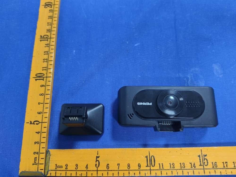
Click to zoom
Application Details
- Equipment Class
- DTS - Digital Transmission System
- Date of Grant
- Sep 01, 2024
- Application Purpose
- Original Equipment
- Date of Application
- Sep 01, 2024
- Equipment Note
- DASH CAM
- Frequency Range
- 2412.00000000 - 2462.00000000
- Company
- NetConn Electronics Co., Ltd
- Country
- Taiwan
Documents & Files
Document Text
Text extracted from the exhibit documents filed with the FCC. Open a document above to read the original.
Users Manual
User Manual 4K+1080P 30fps 6 Glass Lens + AR Coating Front F1.8 & Rear F1.6 Front & Rear 140 Sony STARVIS sensor Front 95 x 80 x 30 mm / 100g Rear 52 x 38 x 30 mm / 28g Video Resolution Screen Lens Aperture Wide-Angle Sensor Rear Camera Only, Always On HDR Video Format Image Format Video Coding EV WiFi Memory Card GPS G-sensor Microphone Beep Code Supercapacitors Power Card Reader Parking Monitor Dimension Weight Snapshot 3.16" LCD TS / MP4 JPG H.264 / H.265 Independent front and rear adjustment Supports snapshot during recording Support 2.4G Supports up to 256 GB (SanDisk SD cards not recommended) Support (Mount) Support Support Support Support (Optional Hardwire Kit required) Material PC+ABS Support USB Type-C 5V 1.5A DS315WG connects to a PC via USB to serve as a card reader BUTTONDESCRIPTION Power On / Off Record Audio On / Off Record Audio On / Off MODE Move Up Enter / Confirm Move down Return Power On / Off Playback Setup Menu Short press to change display output Long Press to turn on WiFi Power On / Off WiFi SSID display On / Off Snapshot during recording LED Light SignalDescription Short press to change display output Long Press to turn off WiFi SSID Steady: Standby / Flashing: Recording / Off: Device Off Steady: WiFi On / Off: WiFi Off Setting/ Playback Standby/ Recording WiFi connected LED Indicator DS315 G G-Sensor EnglishEnglish Time Zone-5 On / OffOff On / OffOn On / OffOn Off / 1 / 3 minutes1 Off / Low / Middle / High SensitivityOff Mute / 20% / 40% / 60% / 80% / 100%80% H.264 / H.265H.265 Off / Time Lapse / Event Monitor Off Km/h / MphMph FUNCTIONOPTIONSDEFAULT Video Resolution Front & Rear (Only Rear support HDR) 4KP30 / 1600P30 / 1440P60 / 1440P30 / 1296P30 / 1080P60 / 1080P30 / 720P120 / 720P60 / 720P30 Front Only 4KP30 / 1600P30 / 1440P60 / 1440P30 / 1296P30 / 1080P60 / 1080P30 / 720P120 / 720P60 / 720P30 4KP30+ 1080P30 4KP30 Video FormatTS / MP4TS Live Video Source Front Camera / Rear Camera / Pictue In Picture Pictue in Picture Loop Recording 1 / 3 / 5 minutes1 Date / TimeManual Time Adjustment Set The Corresponding Time Zone Record Audio Scan QR-code To Download APP APP Download Volume Parking Mode Video Stamp Date Stamp On / Off On GPS Stamp On / OffOn Speed Unit Video Coding Rear Camera Horizontal Flip On / OffOff EV Rear(-1.0 -2/3 -1/3 +0.0 +1/3 +2/3 +1.0)+0.0 EV Front(-1.0 -2/3 -1/3 +0.0 +1/3 +2/3 +1.0)+0.0 Button Sound Screen Off Language Check GPS Signal StrengthGPS Status Format SD Card All Data Will Be Deleted 60 Days Format SD Card Reminder Off / 15 / 30 / 60 Days DefaultReset Default Setting Firmware Version Auto WiFi During Power On After service FB fan Page + RC-E11 Starlight Night Vision Dash Cam 5. FUNCTION OPERATION 5.2 Screen Layout5.1 Setup Menu 6. PRODUCT SPEC7. FAQ & TROUBLE SHOOTING 5.3 Button operation 4KP30 28/01/201808 :21:15 00:00:00 NetConn Electronics Co., Ltd Manufacturer 18F-7, No.77, Sec.1, Xintai 5th Rd., Xizhi Dist., New Taipei City 221, Taiwan 7.1 Memory card cannot display or read : · Ensure the memory card used is Class 10 or above. · Format the memory card in the device before use. 7.2 Failure to power on or freezing : Check below steps (1) Power cable is working and plugged in properly (2) Car charger light is on (3) Remove the SD card (4) Power on and factory reset the device (if this fixes the problem insert the SD card). If the device still can’t power on, please contact our after service. (5) If the problem persists after inserting the SD card, try another SD card. 7.3 Automatic recording Stopped during video capture : · Check if all recorded videos in playback mode are protected. · Ensure that loop recording is set up and format the memory card. 7.4 Interference lines on preview screen : · Adjust the corresponding frequency (50Hz or 60Hz) based on local power supply frequency. · If using a generator, interference lines may be more pronounced, which is normal. 7.5 Foggy video capture : · Check if there is a protective film on the lens, or if the lens or windshield is not clean. · If no issues are found, restart the device. · If the problem persists, consult customer service. 7.6 Some parts of the rear camera footage show streaky blur When installing and positioning the rear camera, please avoid aligning it directly with the defrost lines. 7.7 No image from the rear camera When the rear door is opened, the Type-C signal cable might disconnect from the rear camera. Please unplug and replug the signal cable on the side of the rear camera, then restart the Dash Cam. Recording Time WiFi Status Resolution / FPS GPS Lock Video DateTime Record Audio After service Android iOS MyCAM APP DownlodHow to use MyCAM APP MyCAM APP DownlodHow to use MyCAM APP Rear Camera x1 DS315 G Starlight Night Vision Dash Cam Rear Cam USB power cable Electrostatic sticker Attention: 1. Do not remove or insert the memory card while the device is powered on to avoid damaging the memory card. 2. Please use a MicroSD card of Class 10 or higher( this device supports up to 256GB) 3. Please format the MicroSD card before use. 4. When removing the memory card, be careful as it may quickly eject due to the slot's spring mechanism, potentially causing loss of the memory card. 5. Please regularly format the memory card. Install the dashcam behind the rearview mirror. Before applying the electrostatic sticker, ensure the windshield is clean. Attach the car mount to the electrostatic sticker, and once attached, your GPS mount installation is complete. Install the rear camera at the top of the rear windshield. Before installation, ensure the windshield is clean and dry. Choose a suitable position for the camera and ensure it has the best possible view. Car Charger Cable Rear Camera Cable Cable clips Step1 Install the GPS Antenna Attach the GPS mount to the main unit. Before use, insert the memory card into the slot in the correct direction. Step2 Installing the Car Mount Windshield Rear windshield Step4 Connect cable Install the car charger into the vehicle's cigare…
Text truncated - open the document above for the full version.
External Photos
FCCID:2BH35-DS315WG FCCID:2BH35-DS315WG FCCID:2BH35-DS315WG FCCID:2BH35-DS315WG
Internal Photos
FCCID:2BH35-DS315WG FCCID:2BH35-DS315WG FCCID:2BH35-DS315WG Ant FCCID:2BH35-DS315WG FCCID:2BH35-DS315WG
RF Exposure Info
RFExposureevaluation Exposurecategory:Generalpopulation/uncontrolledenvironment EUTType:ProductionUnit DeviceType:MobileDevice ReferStandard:KDB447498D01GeneralRFExposureGuidancev06 FCCPart2§2.1091 FCCID:2BH35-DS315WG 1.ApplicableStandard Accordingto§1.1307(b)(1),systemsoperatingundertheprovisionsofthissectionshallbeoperatedina mannerthatensuresthatthepublicisnotexposedtoradiofrequencyenergylevelinexcessofthe Commission’sguidelines. Accordingto§1.1310and§2.1093RFexposurerequirement KDB447498v06:MobileandPortableDevicesRFExposureProceduresandEquipmentAuthorization Policies. 2.Requirement AccordingtoKDB447498D01GeneralRFExposureGuidancev06Section4.3.1StandaloneSARtest exclusionconsiderations:“UnlessspecificallyrequiredbythepublishedRFexposureKDBprocedures, standalone1-gheadorbodyand10-gextremitySARevaluationforgeneralpopulationexposureconditions, bymeasurementornumericalsimulation,isnotrequiredwhenthecorrespondingSARTestExclusion Thresholdcondition,listedbelow,issatisfied.Thesetestexclusionconditionsarebasedonsource-based time-averagedmaximumconductedoutputpoweroftheRFchannelrequiringevaluation,adjustedfortune-up tolerance,andtheminimumtestseparationdistancerequiredfortheexposureconditions.22Theminimum testseparationdistanceisdeterminedbythesmallestdistancefromtheantennaandradiatingstructuresor outersurfaceofthedevice,accordingtothehostformfactor,exposureconditionsandplatformrequirements, toanypartofthebodyorextremityofauserorbystander(see5)ofsection4.1).ToqualifyforSARtest exclusion,thetestseparationdistancesappliedmustbefullyexplainedandjustifiedbytheoperating configurationsandexposureconditionsofthetransmitterandapplicablehostplatformrequirements,typically intheSARmeasurementorSARanalysisreport,accordingtotherequiredpublishedRFexposureKDB procedures.WhennootherRFexposuretestingorreportingisrequired,astatementofjustificationand compliancemustbeincludedintheequipmentapproval,inlieuoftheSARreport,toqualifyfortheSARtest exclusion.Whenrequired,thedevicespecificconditionsdescribedintheotherpublishedRFexposureKDB proceduresmustbesatisfiedbeforeapplyingtheseSARtestexclusionprovisions;forexample,handheldPTT two-wayradios,handsets,laptops&tabletsetc.23“ [(max.powerofchannel,includingtune-uptolerance,mW)/(min.testseparationdistance,mm)]·[√f(GHz)] ≤ 3.0for1-gSARand ≤ 7.5for10-gextremitySAR,where: • f(GHz)istheRFchanneltransmitfrequencyinGHz • PoweranddistanceareroundedtothenearestmWandmmbeforecalculation • Theresultisroundedtoonedecimalplaceforcomparison • 3.0and7.5arereferredtoasthenumericthresholdsinthestep2below Thetestexclusionsareapplicableonlywhentheminimumtestseparationdistanceis ≤ 50mmandfor transmissionfrequenciesbetween100MHzand6GHz.Whentheminimumtestseparationdistanceis < 5 mm,adistanceof5mmaccordingto5)insection4.1isappliedtodetermineSARtestexclusion. 3.Limit LimitsforMaximumPermissibleExposure(MPE)/ControlledExposure Frequency Range(MHz) ElectricField Strength(V/m) MagneticField Strength(A/m) PowerDensity (mW/cm²) Averaging Time (minute) LimitsforOccupational/ControlledExposure 0.3–3.0 3.0–30 30–300 300–1500 1500– 100,000 614 1842/f 61.4 / / 1.63 4.89/f 0.163 / / (100)* (900/f 2 )* 1.0 f/300 5 6 6 6 6 6 LimitsforMaximumPermissibleExposure(MPE)/UncontrolledExposure Frequency Range(MHz) ElectricField Strength(V/m) MagneticField Strength(A/m) PowerDensity (mW/cm²) Averaging Time (minute) LimitsforOccupational/ControlledExposure 0.3–3.0 3.0–30 30–300 300–1500 1500– 100,000 614 824/f 27.5 / / 1.63 2.19/f 0.073 / / (100)* (180/f 2 )* 0.2 f/1500 1.0 30 30 30 30 30 F=frequencyinMHz *=Plane-waveequivalentpowerdensity 4.MPECalculationMethod PredicationofMPElimitatagivendistance Equationfrompage18ofOETBulletin65,Edition97-01 S=PG/4πR² Where:S=powerdensity P=powerinputtoantenna G=powergainoftheantennainthedirectionofinterestrelativetoanisotropicradiator R=distancetothecenterofradiationoftheantenna AsdeclaredbytheApplicant,theEUTtransmitswiththemaximumsoure-baedDutyCycleof100%-seethe Usermanual,andtheEUTisawirelessdeviceusedinamobileapplication,atleast20cmfromanybodypart oftheuserornearbypersons;fromthemaximumEUTRFoutputpower,theminimummobileseparation distance,r=20cm,aswellasthegainoftheusedantennais3.01dBiforWLAN,andthepowerdriftfrom Turn-upProcedureprovidebymanufacturerasfollowingstates,theRFpowerdensitycanbeobtained. 5.AntennaInformation useantennascertificatedasfollowsprovidedbymanufacturer; Internal Identification AntennaIdentification inInternalphotos Antennatype andantenna number Operatefrequency band Maximum antennagain 2.4GWIFIAntennaInternalAntenna2400-2500MHz3.01dBi 6.ManufacturingTolerance WIFI2.4G(peak) Frequency(MHz) 11bmode 241224372462 Target(dBm)18.018.018.0 Tolerance±(dB)1.01.01.0 Frequency(MHz) 11gmode 241224372462 Target(dBm)18.018.018.0 Tolerance±(dB)1.01.01.0 Frequency(MHz) 11n(HT20)mode 241224372462 Target(dBm)21.021.021.0 Tolerance±(dB)1.01.01.0 Frequency(MHz) 11n(HT40)mode 242224372452 Target(dBm)21.021.021.0 Tolerance±(dB)1.01.01.0 7.EvaluationResultsforStandalone 6.1 StandaloneMPE AsdeclaredbytheApplicant,theEUTisawirelessdeviceusedinafixapplication,atleast20cmfrom anybodypartoftheuserornearbypersons;fromthemaximumEUTRFoutputpower,theminimum separationdistance,r=20cm,aswellasthegainoftheusedantennarefertoantennainformation,the RFpowerdensitycanbeobtained. ModulationType Outputpower Antenna Gain (dBi) Antenna Gain (linear) MPE (mW/cm2) MPELimits (mW/cm2) dBmmW 2.4GWIFI21.0125.8933.012.0000.050091.0000 Remark: 1.Outputpower(Peak)includingturn-uptolerance; 2.MPEevaluatedistanceis20cmfromusermanualprovidebymanufacturer. 8.Conclusion ThemeasurementresultscomplywiththeFCCLimitper47CFR2.1091fortheuncontrolledRF Exposureofmobiledevice.
Test Report
电话:13538032086传真:0755-27673866 地址: 深圳市宝安区福海街道新填社区凤塘大道50号鑫龙科技园A2栋6楼 承认书 SPECIFICATIONFORAPPROVAL Name:WIFI/BT2.4GHz天线. ItemNo:TYY-TX2508. Custoername:深圳市金豪泰电子有限公司. Companystamp:4.017.0000045. 1、规格 drawingCustomerapprove MADECHECKEDAPPROVED QIU蒋志远唐晓宏 DATE:2023.05.12DATE 电话:13538032086传真:0755-27673866 地址: 深圳市宝安区福海街道新填社区凤塘大道50号鑫龙科技园A2栋6楼 报告主要提供深圳市豪泰克电子有限公司机型各项电性能参数的测试。 TYY-TX2508 天线为WIFI内置天线, WIFI 天线是由 FPC+RF 线组成。(如下 图 1 所示) Thefinishedproductfeatures 电性能指标 ElectricalSpecifications 频率范围 2400~2500MHZ Frequency Range 2400~2500MHZ 电压驻波比 ≤ 2.0 VSWR ≤ 2.0 增益 3.01DBIGAIN3.01DBI 输入阻抗 50Ω Input Impedance 50Ω 机械指标 MechanicalSpecifications 天线颜色 黑色 AntennaColorBLACK 接口形式 无 InputconnectorNO 线长度 1.13 线 80mm Cablelength 1.13 线 80mm 工作温度-40°C~+85°C Working Temperature -40°C~+85°C 工作湿度 20~80% WorkingHumidity 20~80% 电话:13538032086传真:0755-27673866 地址: 深圳市宝安区福海街道新填社区凤塘大道50号鑫龙科技园A2栋6楼 图1TYY-TX2508天线WIFI天线 图2TYY-TX2508天线(线长80mm+/-2mm线径1.13mm) 图3TYY-TX2508线长 此图天线总线长80mm +/- 2mm线径1.13mm剥线长度0.5(内)+1mm(外) 2. 电器性能 2.1WIFI天线的匹配电路 1 2 RF 4 3 电话:13538032086传真:0755-27673866 地址: 深圳市宝安区福海街道新填社区凤塘大道50号鑫龙科技园A2栋6楼 元件编号1234 WIFI最佳NC0欧姆NC 原始(备用)50欧姆匹配 图4OTA微波暗室 图5 测试环境:OTA743暗室,W500/8960/8753ES/5071C,机器背向放置离标准喇叭天4米转台处 电话:13538032086传真:0755-27673866 地址: 深圳市宝安区福海街道新填社区凤塘大道50号鑫龙科技园A2栋6楼 2.3 驻波比 (VSWR) 的测试 2.3.1. 测试的设置 VSWR 测试装置依次的连接为: AgilentE5071B 网络分析仪® 50 欧姆的同轴 Cable ® 120mm 长的 铜管®测试治具 测试治具的处理:从平板 PCB 上天线 50 欧姆测试点处用一根硬质电缆引出 SMA-J 接头,与套有 扼流圈的铜管连接,再依次连接其他装置。 图6WIFI驻波比 电话:13538032086传真:0755-27673866 地址: 深圳市宝安区福海街道新填社区凤塘大道50号鑫龙科技园A2栋6楼 2.3.1.WIFI 驻波比 频率(MHz)24122441245052405750 VSWR 1.31.11.31.51.8 WIFI 无源测试报告 图7三维图效果图 ( 效率和增益) 电话:13538032086传真:0755-27673866 地址: 深圳市宝安区福海街道新填社区凤塘大道50号鑫龙科技园A2栋6楼 电话:13538032086传真:0755-27673866 地址: 深圳市宝安区福海街道新填社区凤塘大道50号鑫龙科技园A2栋6楼 3、建议与结论 此报告是根据客户深圳市豪泰克电子有限公司提机型项目,最终版测得的天线 电器性能。从如上测试数据可以看到,此天线提供了较好的电器性能。 天逸源研发期盼您的确认,谢谢合作!
Test Report
TESTREPORT FCCID:2BH35-DS315WG Product:DASHCAM ModelName: DS315WG+RC-E11,DS318WG+RC-E11,DS319WG+RC- E11,DS315WG,DS318WG,DS319WG Brand:Pernis ReportNo.:NCT24032202 Preparedfor NetConnElectronicsCo.,Ltd 18F-7,No.77,Sec.1,Xintai5thRd.,XizhiDist.,NewTaipeiCity221,Taiwan Preparedby ShenzhenNCTTestingTechnologyCo.,Ltd. A101&2FB2,Fuqiao6thArea,XintianCommunity,FuhaiStreet,BaoanDistrict, Shenzhen,People’sRepublicofChina TEL:400-8868-419 FAX:86-755-27790922 ReportNo.:NCT24032202 Page2of46 Hotline:400-8868-419Fax:86-755-27790922http://www.ncttesting.cn 1TESTRESULTCERTIFICATION Applicant:NetConnElectronicsCo.,Ltd Address:18F-7,No.77,Sec.1,Xintai5thRd.,XizhiDist.,NewTaipeiCity221,Taiwan Manufacturer:NetConnElectronicsCo.,Ltd Address:18F-7,No.77,Sec.1,Xintai5thRd.,XizhiDist.,NewTaipeiCity221,Taiwan Productname:DASHCAM Modelname: DS315WG+RC-E11,DS318WG+RC-E11,DS319WG+RC-E11,DS315WG, DS318WG,DS319WG Standards:FCCCFR47Part15Section15.247 Testprocedure:ANSIC63.10:2013 Dateoftest:Jul.22,2024toAug.09,2024 DateofIssue:Aug.10,2024 ThisdevicedescribedabovehasbeentestedbyNCT,andthetestresultsshowthattheequipmentunder test(EUT)isincompliancewiththeFCCrequirements.Anditisapplicableonlytothetestedsample identifiedinthereport. Thisreportshallnotbereproducedexceptinfull,withoutthewrittenapprovalofNCT,thisdocumentmaybe alteredorrevisedbyNCT,personalonly,andshallbenotedintherevisionofthedocument. TestEngineer: KevenWu/Engineer TechnicalManager: HenryWang/Manager ReportNo.:NCT24032202 Page3of46 Hotline:400-8868-419Fax:86-755-27790922http://www.ncttesting.cn Contents Page 1TESTRESULTCERTIFICATION...............................................................................................................................2 2TESTSUMMARY..........................................................................................................................................................5 3GENERALINFORMATION..........................................................................................................................................6 3.1GENERALDESCRIPTIONOFE.U.T.....................................................................................................................6 3.2CHANNELLIST.....................................................................................................................................................7 3.3TESTSITE............................................................................................................................................................8 3.4TESTSETUPCONFIGURATION............................................................................................................................9 3.5TESTMODE.........................................................................................................................................................9 4EQUIPMENTDURINGTEST....................................................................................................................................10 4.1EQUIPMENTSLIST.............................................................................................................................................10 4.2MEASUREMENTUNCERTAINTY.........................................................................................................................12 4.3DESCRIPTIONOFSUPPORTUNITS...................................................................................................................12 5CONDUCTEDEMISSION..........................................................................................................................................13 5.1E.U.T.OPERATION............................................................................................................................................13 5.2EUTSETUP.......................................................................................................................................................13 5.3TESTSET-UP(BLOCKDIAGRAMOFCONFIGURATION).................................................................................14 5.4MEASUREMENTPROCEDURE............................................................................................................................14 5.5CONDUCTEDEMISSIONLIMIT...........................................................................................................................14 5.6MEASUREMENTDESCRIPTION..........................................................................................................................14 5.7CONDUCTEDEMISSIONTESTRESULT.............................................................................................................14 6RADIATEDSPURIOUSEMISSIONS......................................................................................................................15 6.1EUTOPERATION...............................................................................................................................................15 6.2TESTSETUP......................................................................................................................................................16 6.3SPECTRUMANALYZERSETUP..........................................................................................................................17 6.4TESTPROCEDURE.............................................................................................................................................18 6.5SUMMARYOFTESTRESULTS...........................................................................................................................19 7CONDUCTBANDEDGEANDSPURIOUSEMISSIONSMEASUREMENT....................................................28 7.1TESTPROCEDURE.............................................................................................................................................28 7.2TESTRESULT......................................................................................................................................…
Text truncated - open the document above for the full version.
Test Report
ReportNo.:NCT24032202 Page37of46 Hotline:400-8868-419Fax:86-755-27790922http://www.ncttesting.cn IEEE802.11n_Channel1_20MHz_Antenna0IEEE802.11n_Channel6_20MHz_Antenna0 IEEE802.11n_Channel11_20MHz_Antenna0IEEE802.11n_Channel3_40MHz_Antenna0 IEEE802.11n_Channel6_40MHz_Antenna0IEEE802.11n_Channel9_40MHz_Antenna0 ReportNo.:NCT24032202 Page38of46 Hotline:400-8868-419Fax:86-755-27790922http://www.ncttesting.cn ModeChannelAnt. Center Frequency (MHz) 6dB Bandwidth (MHz) Limit (MHz) Result IEEE802.11b 1 0 24129.305 ≥0.5 PASS 624379.288PASS 1124629.297PASS IEEE802.11g 124129.305PASS 624379.299PASS 1124628.778PASS IEEE 802.11n_20 1241217.53PASS 6243717.57PASS 11246217.55PASS IEEE 802.11n_40 3242235.47PASS 6243735.71PASS 9245235.82PASS TestGraphs IEEE802.11b_Channel1_20MHz_Antenna0IEEE802.11b_Channel6_20MHz_Antenna0 IEEE802.11b_Channel11_20MHz_Antenna0IEEE802.11g_Channel1_20MHz_Antenna0 ReportNo.:NCT24032202 Page39of46 Hotline:400-8868-419Fax:86-755-27790922http://www.ncttesting.cn IEEE802.11g_Channel6_20MHz_Antenna0IEEE802.11g_Channel11_20MHz_Antenna0 IEEE802.11n_Channel1_20MHz_Antenna0IEEE802.11n_Channel6_20MHz_Antenna0 IEEE802.11n_Channel11_20MHz_Antenna0IEEE802.11n_Channel3_40MHz_Antenna0 ReportNo.:NCT24032202 Page40of46 Hotline:400-8868-419Fax:86-755-27790922http://www.ncttesting.cn IEEE802.11n_Channel6_40MHz_Antenna0IEEE802.11n_Channel9_40MHz_Antenna0 ReportNo.:NCT24032202 Page41of46 Hotline:400-8868-419Fax:86-755-27790922http://www.ncttesting.cn 9MaximumPeakOutputPower TestRequirement:FCCCFR47Part15Section15.247 TestMethod:ANSIC63.10:2013 TestLimit: Regulation15.247(b)(3),Forsystemsusingdigitalmodulationinthe902- 928MHz,2400-2483.5MHz,and5725-5850MHzbands:1Watt.Asan alternativetoapeakpowermeasurement,compliancewiththeoneWatt limitcanbebasedonameasurementofthemaximumconductedoutput power. 9.1TestProcedure ThemaximumpeakconductedoutputpowermaybemeasuredusingabroadbandpeakRFpower meter.ThepowermetershallhaveavideobandwidththatisgreaterthanorequaltotheDTS bandwidthandshallutilizeafast-respondingdiodedetector. 9.2TestResult ModeTestChannel PeakOutputPower (dBm) LIMIT (dBm) Result 802.11b Low17.3830.00PASS Middle17.2930.00PASS High17.2430.00PASS 802.11g Low17.1230.00PASS Middle16.9930.00PASS High17.0130.00PASS 802.11nHT20 Low19.6330.00PASS Middle19.5630.00PASS High19.6030.00PASS 802.11nHT40 Low19.8530.00PASS Middle19.9230.00PASS High19.9330.00PASS ReportNo.:NCT24032202 Page42of46 Hotline:400-8868-419Fax:86-755-27790922http://www.ncttesting.cn 10PowerSpectraldensity TestRequirement:FCCCFR47Part15Section15.247 TestMethod:ANSIC63.10:2013 TestLimit:Regulation15.247(f)Thepowerspectraldensityconductedfromthe intentionalradiatortotheantennaduetothedigitalmodulation operationofthehybridsystem,withthefrequencyhoppingoperation turnedoff,shallnotbegreaterthan8dBminany3kHzbandduring anytimeintervalofcontinuoustransmission. 10.1TestProcedure 1.RemovetheantennafromtheEUTandthenconnectalowRFcablefromtheantennaporttothe spectrum. 2.Setthespectrumanalyzer:RBW=3kHz.VBW=9.1kHz,Span=1.5timestheDTSchannelbandwidth(6 dBbandwidth).Sweep=auto;DetectorFunction=Peak.Trace=Maxhold. 3.Allowthetracetostabilize.Usethemarker-deltafunctiontodeterminetheseparationbetweenthepeaks oftheadjacentchannels.ThelimitisspecifiedinoneofthesubparagraphsofthisSectionSubmitthisplot. 10.2TestResult ModeChannel PSD (dBm/3kHz) Ant.0 Limit (dBm/3kHz) Result IEEE802.11b 1-4.422 ≤8 PASS 6-0.839PASS 11-2.145PASS IEEE802.11g 1-1.064PASS 6-9.347PASS 114.571PASS IEEE802.11n_20 1-14.044PASS 6-14.077PASS 11-13.961PASS IEEE802.11n_40 3-16.456PASS 6-16.709PASS 9-16.559PASS ReportNo.:NCT24032202 Page43of46 Hotline:400-8868-419Fax:86-755-27790922http://www.ncttesting.cn TestGraphs IEEE802.11b_Channel1_20MHz_Antenna0IEEE802.11b_Channel6_20MHz_Antenna0 IEEE802.11b_Channel11_20MHz_Antenna0IEEE802.11g_Channel1_20MHz_Antenna0 IEEE802.11g_Channel6_20MHz_Antenna0IEEE802.11g_Channel11_20MHz_Antenna0 ReportNo.:NCT24032202 Page44of46 Hotline:400-8868-419Fax:86-755-27790922http://www.ncttesting.cn IEEE802.11n_Channel1_20MHz_Antenna0IEEE802.11n_Channel6_20MHz_Antenna0 IEEE802.11n_Channel11_20MHz_Antenna0IEEE802.11n_Channel3_40MHz_Antenna0 IEEE802.11n_Channel6_40MHz_Antenna0IEEE802.11n_Channel9_40MHz_Antenna0 ReportNo.:NCT24032202 Page45of46 Hotline:400-8868-419Fax:86-755-27790922http://www.ncttesting.cn 11AntennaApplication 11.1AntennaRequirement Forintentionaldevice,accordingtoFCC47CFRSection15.203,anintentional radiatorshallbedesignedtoensurethatnoantennaotherthanthatfurnishedbythe responsiblepartyshallbeusedwiththedevice.AndaccordingtoFCC47CFR Section15.247(b),iftransmittingantennasofdirectionalgaingreaterthan6dBiare used,thepowershallbereducedbytheamountindBthatthedirectionalgainofthe antennaexceeds6dBi. 11.2Result TheEUT’Santenna,permanentattachedantenna,isInternalAntenna.Theantenna’s gainis3.01dBiandmeetstherequirement. ReportNo.:NCT24032202 Page46of46 Hotline:400-8868-419Fax:86-755-27790922http://www.ncttesting.cn 12TestSetupandEUTPhotos Referencetotheattachmentfordetails. ******THEENDREPORT******
Test Setup Photos
FCCID:2BH35-DS315WG RadiatedEmission (Below1G) RadiatedEmission (Above1G)
Contact Information
Applicant
Eric Ko(Product Manager)
Technical Contact
Test Firm
SHENZHEN NCT TESTING TECHNOLOGY CO., LTD.Henry Wang
[email protected]0755-27790922
Technical Specifications
| # | Rule Parts | Frequency Range | Power Output |
|---|---|---|---|
| 1 | 15C | 2.41 GHz - 2.46 GHz | 98.40 mW |