2BH3B-M880Massage Chair
Ningbo Zhouqi Health Technology Co., Ltd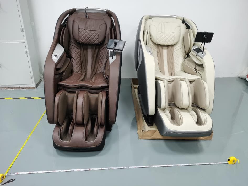
Click to zoom
Application Details
- Equipment Class
- DSS - Part 15 Spread Spectrum Transmitter
- Date of Grant
- Aug 07, 2024
- Application Purpose
- Original Equipment
- Date of Application
- Aug 07, 2024
- Equipment Note
- Massage Chair
- Frequency Range
- 2402.00000000 - 2480.00000000
- Country
- China
Documents & Files
Document Text
Text extracted from the exhibit documents filed with the FCC. Open a document above to read the original.
Attestation Statements
(Ningbo Zhouqi Health Technology Co., Ltd) (July 31, 2024) Eurofins Electrical and Electronic Testing NA, Inc. 914 West Patapsco Avenue Baltimore, MD 21230 RE: Attestation Statements Part 2.911(d)(5)(i) request for (FCC ID: 2BH3B-M880) [Ningbo Zhouqi Health Technology Co., Ltd] (“the applicant”) certifies that the equipment for which authorization is sought is not “covered” equipment prohibited from receiving an equipment authorization pursuant to section 2.903 of the FCC rules. Sincerely, (Applicant signature) (Applicant printed name) Hongliang liu (Ningbo Zhouqi Health Technology Co., Ltd) (July 31, 2024) Eurofins Electrical and Electronic Testing NA, Inc. 914 West Patapsco Avenue Baltimore, MD 21230 RE: Attestation Statements Part 2.911(d)(5)(ii) request for (FCC ID: 2BH3B-M880) [Ningbo Zhouqi Health Technology Co., Ltd] (“the applicant”) certifies that, as of the date of the filing of the application, the applicant is not identified on the Covered List as an entity producing “covered” equipment. Sincerely, (Applicant signature) (Applicant printed name) Hongliang liu
Attestation Statements
Attestation Statements (July 31, 2024) TO: Federal Communications Commission Authorization and Evaluation Division 7435 Oakland Mills Road Columbia, MD 21046, USA RE: Attestation Statements Part 2.911(d)(7) request for (FCC ID: 2BH3B-M880 ) (Ningbo Zhouqi Health Technology Co., Ltd), the undersigned, hereby authorize (Infinite Creative Enterprises, Inc) to act as our designated U.S. agent for service of process, (Ningbo Zhouqi Health Technology Co., Ltd) accepts to maintain an agent for no less than one year after the grantee has terminated all marketing and importation or the conclusion of any Commission-related proceeding involving the equipment. (Infinite Creative Enterprises, Inc) accepts the responsibility to act as designated U.S. agent for service of process, provides an agent for no less than one year after the grantee has terminated all marketing and importation or the conclusion of any Commission-related proceeding involving the equipment. Applicant Information: Company name: Ningbo Zhouqi Health Technology Co., Ltd Contact Name: Hongliang liu Address: No. 517, Guanshen Road, Binhai Economic Development District, Cixi, Zhejiang Province, China Telephone No: 13538214502 Email: [email protected] FRN: 0035757772 Signature [Hongliang liu] U.S. Agent Information: Company Name: Infinite Creative Enterprises, Inc Address: 72 Stard Road Seabrook, NH 3874 United States Contact Name: David Figler Telephone No: (603) 910-5207 Email: [email protected] FRN: 0033540683 Signature [David Figler]
Cover Letter(s)
Ningbo Zhouqi Health Technology Co., Ltd (July 31, 2024) Eurofins Electrical and Electronic Testing NA, Inc. 914 West Patapsco Avenue Baltimore, MD 21230 RE: CONFIDENTIALITY REQUEST FOR (Massage Chair / Kyota M880 Joubu / FCC ID: 2BH3B-M880) To Whom It May Concern: This letter serves as an official request for confidentiality under sections 0.457 and 0.459 of CFR 47. We have requested that the Exhibits Long-Term Confidentiality Short-Term Confidentiality NOTE 2 ID Label/Location No No Attestation Statement No No External Photos No ☐ Block Diagram ☒ ☐ Schematics ☒ ☐ Test Report No No Test Setup Photos No ☐ User’s Manual ☐ NOTE 1 ☒ Internal Photos ☐ NOTE 1 ☒ Parts List / Tune Up ☐ ☐ RF Exposure Info No No Operational Description ☒ ☐ Cover Letter(s) No No SDR Software / Security Info ☐ No required to be submitted with this application be permanently withheld from public review. Above mentioned document contains detailed system and equipment description are considered as proprietary information in operation of the equipment. The public disclosure of above documents might be harmful to our company and would give competitor an unfair advantage in the market. Please contact me if there is any information you may need. Sincerely, Signature: Name: Hongliang liu Title: R&d director
Cover Letter(s)
Ningbo Zhouqi Health Technology Co., Ltd (July 31, 2024) Eurofins Electrical and Electronic Testing NA, Inc. 914 West Patapsco Avenue Baltimore, MD 21230 RE: LETTER OF AGENT AUTHORIZATION To Whom It May Concern: We, the undersigned, hereby authorize (Shenzhen CTB Testing Technology Co., Ltd.) to act on our behalf in all matters relating to application for equipment authorization, including the signing of all documents relating to these matters. We also hereby certify that no party to the application authorized hereunder is subject to the denial of benefits, including FCC benefits, pursuant to Section 5301 of the Anti-Drug Abuse Act of 1988, 21 U.S.C.853(a). This agreement expires one year from the current date. Sincerely, Signature: Name: Hongliang liu Title: R&d director
External Photos
Shenzhen CTB Testing Technology Co., Ltd. Report Tel: 4008-707-283 Web: http://www.ctb-lab.net Page 1 of 4 Model: Kyota M880 Joubu External Photos Shenzhen CTB Testing Technology Co., Ltd. Report Tel: 4008-707-283 Web: http://www.ctb-lab.net Page 2 of 4 Shenzhen CTB Testing Technology Co., Ltd. Report Tel: 4008-707-283 Web: http://www.ctb-lab.net Page 3 of 4 Shenzhen CTB Testing Technology Co., Ltd. Report Tel: 4008-707-283 Web: http://www.ctb-lab.net Page 4 of 4
ID Label/Location Info
FCC ID LABEL: Label Location:
RF Exposure Info
Shenzhen CTB Testing Co., Ltd. FCC ID:2BH3B-M880 Portable device According to §15.247(e)(i) and §1.1307(b)(1), systems operating under the provisions of this section shall be operated in a manner that ensures that the public is not exposed to radio frequency energy level in excess of the Commission’s guidelines. According to KDB447498 D01 General RF Exposure Guidance V06 The 1-g SAR and 10-g SAR test exclusion thresholds for 100 MHz to 6 GHz at test separation distances ≤ 50 mm are determined by: [(max. power of channel, including tune-up tolerance, mW)/(min. test separation distance, mm)]·[√f(GHZ)] ≤ 3.0 for 1-g SAR and ≤ 7.5 for 10-g extremity SAR, where: • f(GHZ) is the RF channel transmit frequency in GHz • Power and distance are rounded to the nearest mW and mm before calculation • The result is rounded to one decimal place for comparison When the minimum test separation distance is < 5 mm, a distance of 5 mm is applied to determine SAR test exclusion. EDR: Modulation Channel Freq. (GHz) Conduct ed power (dBm) Conducte d power (mW) Tune-up power (dBm) Max tune-up power (dBm) Max tune-up power (mW) Distance (mm) Result calculatio n SAR Exclusion threshold SAR test exclusion 2.402 1.878 1.54 1±1 2.00 1.58 <5 0.49127 3.00 YES 2.441 1.726 1.49 1±1 2.00 1.58 <5 0.49524 3.00 YES 2.480 1.382 1.37 1±1 2.00 1.58 <5 0.49918 3.00 YES 2.402 2.682 1.85 2±1 3.00 2.00 <5 0.61847 3.00 YES 2.441 2.469 1.77 2±1 3.00 2.00 <5 0.62347 3.00 YES 2.480 2.062 1.61 2±1 3.00 2.00 <5 0.62843 3.00 YES 2.402 2.899 1.95 2±1 3.00 2.00 <5 0.61847 3.00 YES 2.441 2.727 1.87 2±1 3.00 2.00 <5 0.62347 3.00 YES 2.480 2.37 1.73 2±1 3.00 2.00 <5 0.62843 3.00 YES GFSK π /4DQPSK 8DQPSK Conclusion: For the max result : 0.62843≤ FCC Limit 3.0 for 1g SAR.
Test Report
WLT3266H antenna Small Size 2.4 GHz PCB antenna 1 INTRODUCTION and considerations for complying with regulatory limits when using this design. Thesuggestedantennadesignrequires no morethanmmof space a ndensuresa VSWRratiooflesstha n2 acrossthe2.4GHzISMband when connected toa 50ohm source. T he PCB antenna used on t he WLT3266H reference design is described in this a pplication note.Even if the antenna presented is for a WLT3266H it can be use d in all designs, 2.4 GHz especially where small re quired space is for the antenna. This a pplication note describes the a ntenna dimensions, the RF performance Figure 1 : H ANTENNA DESIGN The PCB antenna on the WLT3266H reference design is a meandered Inverted F Antenna (IFA) . The IFA was designed to match an impedance of 50 ohm at 2.45 GHz. Thus no additional mat ching components are necessary. 2 Design Goals The reflection at the feed point of the antenna determines how much of the applied power is delivered to the antenna. A reflection of less than -10 dB across the 2.4 GHz ISM band, when connected to a 50 ohm source, was a design goal. Reflection of less than -10dB, or VSWR less than 2, ensures that more than 90% of the available power is delivered to the antenna. Bandwidth is in this document defined as the fequency band where more than 90% of the available power is delivered to the antenna. Another design goal was to fit the size of the PCB antenna on a WLT3266H and to obtain good performance also when the dongle is connected to a computer. 2.1 Simulation IE3D from Zeland, which is an electromagnetic simulation tool, was used to design the antenna. The accuracy of the simulation is controlled by the mesh. An increase of the mesh increases the simulation time. Thus, for initial simulations mesh = 1 should be used. When a fairly good result is achieved a higher mesh should be used to obtain more accurate results. Comparison of simulation and measurement results shows that the measured reflection is between the result obtained with mesh = 5 and mesh = 1 ; see Figure 2 for details. 2.2 -3 - 12 也 飞, - 21 -2 7 - 1 5 · 1 8 - 9 ...• Simulated mesh6 -Simulated mesh1 一 ···· ·&T o --, .... ,,,, ........ 01· …- Measured free s p ,oe 3 , ·24 · 。 -3 “ 6 - 9 - 1 2 国 飞, · 1 5 - 1 8 -2 7 - 21 -30 3 28 2 7 24 25 26 Froqu•ncy (GHz) 23 22 2. - 30 2 Figure 2: C。mparisonof Simulation and Measurements Results 2.3 Layout and Implementation Small changes of the antenna dimensions may have large impact on the performance. Therefore it is strongly recommended to make an exact copy of the reference design to achieve optimum pe斤。rmance. The easiest way to implement the antenna is to import the gerber or DXF file showing the antenna layout. The imported file can be used as a template when drawing the antenna. By using this procedure it should be possible to make an exact copy. If the PCB CAD tool being used does not suppo叫impo时of DXF or gerber files, Figu「e 3 and Table 1 should be used to ensure correct implementation. It is recommended to gene「ate a gerber file for compa「 isοn with IFA_USB.spl when making a manual implementation. Most g erber viewers have the possibility to impo同several gerbe「 files at the same time. Thus by placing the gerber file, showing the manually implemented antenna, on top of IFA_USB.spl it is easy to ve「ify that the antenna is correctly implemented. It is also recommended to use the same thickness and type of PCB material as used in the reference design. Information about the PCB can be found in a separate readme file included in the reference design. To compensate for a thicker/thinner PCB the antenna could be made slightly shorter/longer. . Figure 3: Antenna Dimensions Table 1: Antenna Dimensions 3 TEST RESULTS Reflection, radiation pattern and variation of output power across a wide frequency band were measured to verify the pe斤ormance of the PCB antenna. Measurements of the dongle in f「ee space and when connected to a laptop were performed to verify that the antenna is suitable both fo「 H d esigns and in a standalone application. Free space is in this document i nter preted as a measurement pe斤。rmed without connecting the dongle to a computer. In such a m easurement the d ongle is only powered by a b attery. 3 .1 Reflecti。n All the 「eflectionmeasurements were performed with a network analyzer connected to a semi-rigid coax cable, which was soldered to the feed point of the antenna. Because of the small size antenna and the small ground plane this kind of measurements is heavily affected by the presence and placement of the coax cable. This influence can「esult in a small uncertainty in resonance frequency and measured 「eflection.Typically different placement of the semi-rigid coax cable could change the resonance frequency with 5 -10 MHz and the reflection with 3 - 4 dB. Free space - 2 -4 叫 6 叫 B - 1 0 - 12 百 -14 - 1 6 - 1 8 - 2 0 ·22 I ” ·24 I· ·26 I 甲 - 2 8 2.1 T .」---- ’ I 2.2 啥- 一-叫 τ T l 2.3 With。ut test pins 丁’””- r 」-- , With plastic I " ’ I τ . ι I I " I -----←-- - - 一咆- -一一一一一一 千 + 一 ← ”’ ’1 , τ 2.4 2 5 2.6 2. 7 2.8 Frequency (GHz) ' .,. .,. 丁 J」 " -一一一 叫卜 T T l 2.9 。 - 2 -4 而 - 8 - 1 0 ·12 回 - 1 4 百 - 1 6 - 1 8 - 2 0 - 2 2 -2 4 - 2 6 - 2 8 3 Figu『-e 4: Influence of Plastic Encapsulation and Test Pins A small part on the WLT3266H PCB is equipped with test pins. These are intended for use duri ng development. This part of the PCB will typically be omitted in a final application. The red an d green graph on Figure 4 shows that removing this part of the PCB has a small impact on the perormance. Figure 4 also shows that plastic encapsulation of the dongle will shift the resonance frequency to a lower frequency. This can be compensated by making the antenna slightly shorter. The size of the ground plane affects the perormance of the PCB antenna. Connecting the WLT3266H to a co mputer incre ases the si ze of the ground plane and t hus the performance is affect ed. Figure 5 shows how the perormance is affec ted when the WLT3266H is connec…
Text truncated - open the document above for the full version.
Test Report
TEST REPORT Compiled by: Reviewed by: Approved by: Zhou Kui Arron Liu Bin Mei / Director Note: If there is any objection to the inspection results in this report, please submit a written report to the company within 15 days from the date of receiving the report. The test report is effective only with both signature and specialized stamp. This result(s) shown in this report refer only to the sample(s) tested. Without written approval of Shenzhen CTB Testing Technology Co., Ltd. this report can’t be reproduced except in full. The tested sample(s) and the sample information are provided by the client. “*” indicates the testing items were fulfilled by subcontracted lab. “#” indicates the items are not in CNAS accreditation scope. Product Name: Massage Chair FCC ID: 2BH3B-M880 Trademark: N/A Model Number: Kyota M880 Joubu Prepared For: Ningbo Zhouqi Health Technology Co., Ltd Address: No. 517, Guanshen Road, Binhai Economic Development District, Cixi, Zhejiang Province, China Manufacturer: Ningbo Zhouqi Health Technology Co., Ltd Address: No. 517, Guanshen Road, Binhai Economic Development District, Cixi, Zhejiang Province, China Prepared By: Shenzhen CTB Testing Technology Co., Ltd. Address: 1&2/F., Building A, No.26, Xinhe Road, Xinqiao, Xinqiao Street, Bao'an District, Shenzhen, Guangdong, China Sample Received Date: Apr. 16, 2024 Sample tested Date: Apr. 16, 2024 to May. 07, 2024 Issue Date: May. 07, 2024 Report No.: CTB240507053RFX Test Standards FCC CFR Title 47 Part 15 Subpart C Section 15.247 ANSI C63.10:2013 Test Results PASS Remark: This is Bluetooth radio test report. Shenzhen CTB Testing Technology Co., Ltd. Report No.: CTB240507053RFX Report Tel: 4008-707-283 Web: http://www.ctb-lab.net Page 2 of 58 TABLE OF CONTENT Test Report Declaration Page 1. VERSION .......................................................................... 4 2. TEST SUMMARY ................................................................... 5 3. MEASUREMENT UNCERTAINTY ..................................................... 6 4. PRODUCT INFORMATION AND TEST SETUP ......................................... 7 4.1 Product Information ................................................................... 7 4.2 Test Setup Configuration ............................................................... 7 4.3 Support Equipment.................................................................... 7 4.4 Channel List ......................................................................... 8 4.5 Test Mode ........................................................................... 8 4.6 Test Environment ..................................................................... 8 5. TEST FACILITY AND TEST INSTRUMENT USED ....................................... 9 5.1 Test Facility .......................................................................... 9 5.2 Test Instrument Used .................................................................. 9 6. AC POWER LINE CONDUCTED EMISSION ............................................ 11 6.1 Block Diagram Of Test Setup .......................................................... 11 6.2 Limit ............................................................................... 11 6.3 Test procedure ...................................................................... 11 6.4 Test Result ......................................................................... 13 7. RADIATED SPURIOUS EMISSION ................................................... 15 7.1 Block Diagram Of Test Setup .......................................................... 15 7.2 Limit ............................................................................... 15 7.3 Test procedure ...................................................................... 16 7.4 Test Result ......................................................................... 17 8. BAND EDGE AND RF COUNDUCTED SPURIOUS EMISSIONS .......................... 26 8.1 Block Diagram Of Test Setup .......................................................... 26 8.2 Limit ............................................................................... 26 8.3 Test procedure ...................................................................... 26 8.4 Test Result ......................................................................... 27 9. COUDUCTED PEAK OUTPUT POWER ............................................... 34 9.1 Block Diagram Of Test Setup .......................................................... 34 9.2 Limit ............................................................................... 34 9.3 Test procedure ...................................................................... 34 9.4 Test Result ......................................................................... 35 10. 20DB OCCUPIED BANDWIDTH ..................................................... 39 10.1 Block Diagram Of Test Setup ......................................................... 39 10.2 Limit .............................................................................. 39 10.3 Test procedure ..................................................................... 39 10.4 Test Result ........................................................................ 39 11. CARRIERFREQUENCIES SEPARATION ............................................. 43 11.1 Block Diagram Of Test Setup ......................................................... 43 11.2 Limit .............................................................................. 43 11.3 Test procedure ..................................................................... 43 11.4 Test Result ........................................................................ 43 12. HOPPING CHANNEL NUMBER ..................................................... 47 12.1 Block Diagram Of Test Setup ......................................................... 47 12.2 Limit .............................................................................. 47 12.3 Test procedure ..................…
Text truncated - open the document above for the full version.
Test Setup Photos
Shenzhen CTB Testing Technology Co., Ltd. Report Tel: 4008-707-283 Web: http://www.ctb-lab.net Page 1 of 2 Model: Kyota M880 Joubu Radiated Emission Below 1G Above 1G Shenzhen CTB Testing Technology Co., Ltd. Report Tel: 4008-707-283 Web: http://www.ctb-lab.net Page 2 of 2 Conducted emissions
Contact Information
Applicant
Hongliang liu
Technical Contact
Ningbo Zhouqi Health Technology Co., LtdHongliang liu
[email protected]13538214502
No. 517, Guanshen Road, · Cixi, Zhejiang Province, · China
Test Firm
Shenzhen CTB Testing Technology Co., Ltd.Rita Xiao
[email protected]86-13538218145
Technical Specifications
| # | Rule Parts | Frequency Range | Power Output |
|---|---|---|---|
| 1 | 15C | 2.40 GHz - 2.48 GHz | 1.95 mW |