2BH7FBE65V3BE11000 Whole Home Mesh Wi-Fi 7 System
TP-Link Systems Inc.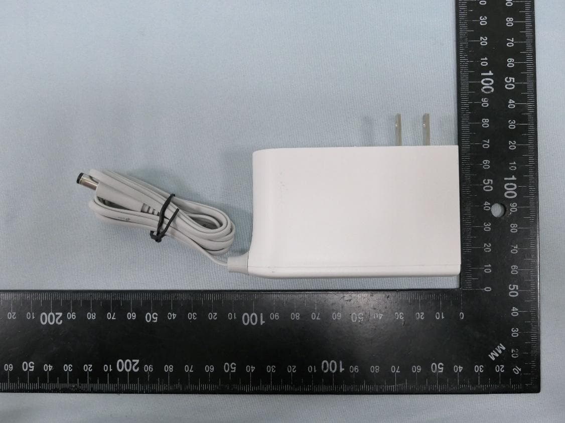
Click to zoom
Application Details
- Equipment Class
- 6ID - 15E 6 GHz Low Power Indoor Access Point
- Date of Grant
- Mar 02, 2026
- Application Purpose
- Original Equipment
- Equipment Note
- BE11000 Whole Home Mesh Wi-Fi 7 System
- Frequency Range
- 6115.00000000 - 7095.00000000
- Company
- TP-Link Systems Inc.
- Country
- United States
Documents & Files
Document Text
Text extracted from the exhibit documents filed with the FCC. Open a document above to read the original.
Users Manual
Deco BE65_Installation and User Guide Table of Contents About This Guide This guide provides a brief introduction to BE11000 Whole Home Mesh Wi-Fi 7 System and regulatory information. Features available in Deco may vary by model and software version. Deco availability may also vary by region or ISP. All images, steps, and descriptions in this guide are only examples and may not reflect your actual Deco experience. Conventions In this guide, the following conventions are used: ConventionDescription DecoStands for Deco Whole Home Mesh Wi-Fi System/Unit. Underline Underlined words or phrases are hyperlinks. You can click to redirect to a website or a specific section. Bold Contents to be emphasized and texts on the web page are in bold, including the menus, items, buttons and so on. > The menu structures to show the path to load the corresponding page. For example, Settings > System Tools > Firmware Upgrade means the Firmware Upgrade page is under the System Tools menu that is located in the Settings tab. Note:Ignoring this type of note might result in a malfunction or damage to the device. Tip:Indicates important information that helps you make better use of your device. More Info Specific product information can be found on the product page at https://www.tp-link.com. A Technical Community is provided for you to discuss our products at https://community.tp-link.com. Our Technical Support contact information can be found at the Help center of the Deco app and the Contact Technical Support page at https://www.tp-link.com/support. Disclaimer Speed/Coverage/Device Quantity Disclaimer Maximum wireless signal rates are the physical rates derived from IEEE Standard 802.11 specifications. Actual wireless data throughput and wireless coverage, and quantity of connected devices are not guaranteed and will vary as a result of network conditions, client limitations, and environmental factors, including building materials, obstacles, volume and density of traffic, and client location. MU-MIMO Disclaimer Use of MU-MIMO requires clients to also support MU-MIMO. IoT Compatibility Disclaimer IoT compatibility refers only to smart devices that can be controlled via the Deco app. Other wireless devices can still connect to Deco for normal Wi-Fi use. Seamless Roaming Disclaimer Clients need to support 802.11k/v/r and may require additional set up. Performance may vary depending on the client device. 1. Appearance Each Deco has an LED that changes color according to its status, a WPS button, four 2.5 Gbps WAN/LAN ports, a USB port, a power slot, and a Reset button. See the explanation below: LED Explanation LEDIndication Pulse YellowDeco is resetting. Solid YellowDeco is starting up. Pulse BlueDeco is ready for setup. Solid BlueDeco is setting up. Pulse GreenDeco is upgrading firmware. Solid GreenDeco is all set up and connected to the internet. Pulse RedThe satellite Deco is disconnected from the main Deco. LEDIndication Solid RedThe main Deco is disconnected from the internet. Ports and Buttons Port/ButtonDescription WPS Button Press this WPS button, and immediately press the WPS buttonon your client device to start the WPS process. Reset Button Press for 1 second and release to reset Deco to factory default settings. The light changing from pulsing yellow to solid yellow indicates a successful reset. Port/ButtonDescription 2.5 Gbps WAN/LAN port For connecting Deco to your modem, the Ethernet outlet, or other internet devices. USB PortFor connecting a USB storage device to Deco. Power SlotFor connecting Deco to the power socket via the provided power adapter. 2. Set Up Your Deco Network First, let's start by setting up the Deco network. Get the TP-Link Deco app for iOS or Android, then follow the app to walk through the setup. 1. Get the Deco app Scan the QR code below or go to Google Play or the App Store to download the Deco app. Install the app on your Android or iOS smartphone or tablet. 2. Log in or sign up with TP-Link ID Open the app and log in with your TP-Link ID. If you don’t have a TP-Link ID, create one first. Note: If you forgot your login password, tap Forgot Password?. The app will help you reset your password. 3. Create a Network In the Deco app, tap the + button on the top right corner of the homepage, then select Create a Network. 4. Plug in your Deco Plug in your Deco and wait until your Deco's LED pulses blue, then your phone/tablet will connect to the Deco's default Wi-Fi automatically. Note: You can turn on Bluetooth on your phone/tablet in advance for a quicker setup. 5. Connect your Deco Power off your modem. Connect your Deco to the modem and power it on. If you don't have a modem, connect your Deco to a networking device's LAN port. or 6. Specify your Deco's location Select or custom a location for your Deco. The location will be used as the name of your Deco. 7. Connect your Deco to the internet Select the internet connection type and enter the information. If you are not sure, contact your internet service provider. 8. Create your Wi-Fi network Set a network name and a password. These will be the name and password you use to connect your devices to Wi-Fi. 9. Setup complete Your Deco network is now up. You can connect your devices to the Deco network for better connections. Additionally, add more Deco units to expand the Wi-Fi coverage. Troubleshooting Solutions to common problems during setup or use are provided here for reference. Follow the steps and the provided link below to diagnose and solve problems you might experience with your Deco. If problems still exist, contact us: TP-Link Product Support Q1. What should I do if I fail to configure the main Deco and get stuck on “We couldn't find Deco”? Refer to the guide Main Deco Failed to Complete Setup or follow the video What to do if I fail to configure the main Deco and get stuck on “We couldn't find Deco”? Q2. What should I do if I fail to configure the satellite Deco and get stuck on “We couldn't find another Deco”? Refer t…
Text truncated - open the document above for the full version.
RF Exposure Info
MRT Technology (Taiwan) Co., Ltd Report No.: 2511TW0118-U7 Phone: +886-3-3288388 Report Version: 1.0 Web: www.mrt-cert.com Issue Date: 2026-02-12 Page Number: 1 of 13 RF Exposure Evaluation Declaration FCC ID : 2BH7FBE65V3 Applicant : TP-Link Systems Inc. Application Type : Certification Product : BE11000 Whole Home Mesh Wi-Fi 7 System Model No. : Deco BE65 Series Model No. : Deco BE63, Deco WB22000 Brand Name : tp-link FCC Rule Part(s) : FCC Part 2.1091 FCC Classification : Digital Transmission System (DTS) Unlicensed National Information Infrastructure (NII) 15E 6GHz Low Power Indoor Access Point (6ID) Received Date : November 27, 2025 Test By : ( Owen Tsai ) Reviewed By : ( Paddy Chen ) Approved By : ( Chenz Ker) The test results relate only to the samples tested. The test results shown in the test report are traceable to the national/international standards through the calibration of the equipment and evaluated measurement uncertainty herein. The test report shall not be reproduced except in full without the written approval of MRT Technology (Taiwan) Co., Ltd. Report No.: 2511TW0118-U7 Page Number: 2 of 13 Revision History Report No. Version Description Issue Date Note 2511TW0118-U7 1.0 Original Report 2026-02-12 Report No.: 2511TW0118-U7 Page Number: 3 of 13 CONTENTS Description Page 1. INTRODUCTION ................................................................................................................... 5 1.1. Scope ........................................................................................................................ 5 1.2. MRT Test Location .................................................................................................... 5 2. PRODUCT INFORMATION ................................................................................................... 6 2.1. Feature of Equipment under Test .............................................................................. 6 2.2. Description of Available Antennas .............................................................................. 7 2.3. Device Classification .................................................................................................. 8 2.4. Applied Standards ..................................................................................................... 8 3. RF Exposure Evaluation ..................................................................................................... 9 3.1. Limits ......................................................................................................................... 9 3.2. MPE Exemptions ......................................................................................................10 3.3. Test Result of RF Exposure Evaluation .....................................................................13 Report No.: 2511TW0118-U7 Page Number: 4 of 13 General Information Applicant TP-Link Systems Inc. Applicant Address 10 Mauchly, Irvine, CA 92618 Manufacturer TP-Link Systems Inc. Manufacturer Address 10 Mauchly, Irvine, CA 92618 Test Site MRT Technology (Taiwan) Co., Ltd Test Site Address No. 38, Fuxing Second Rd., Guishan Dist., Taoyuan City 333, Taiwan (R.O.C) MRT FCC Registration No. 291082 Test Device Serial No. N/A Production Pre-Production Engineering Test Facility / Accreditations 1. MRT facility is a FCC registered (Reg. No. 291082) test facility with the site description report on file and is designated by the FCC as an Accredited Test Firm. 2. MRT facility is an IC registered (MRT Reg. No. 21723) test laboratory with the site description on file at Industry Canada. 3. MRT Lab is accredited to ISO 17025 by the Taiwan Accreditation Foundation (TAF Cert. No. 3261) in EMC, Telecommunications and Radio testing for FCC (Designation Number: TW3261), Industry Canada, EU and TELEC Rules. Report No.: 2511TW0118-U7 Page Number: 5 of 13 1. INTRODUCTION 1.1. Scope Measurement and determination of electromagnetic emissions (EMC) of radio frequency devices including intentional and/or unintentional radiators for compliance with the technical rules and regulations of the Federal Communications Commission and the Innovation, Science and Economic Development Canada and Certification and Engineering Bureau. 1.2. MRT Test Location The map below shows the location of the MRT LABORATORY, its proximity to the Taoyuan City. These measurement tests were conducted at the MRT Technology (Taiwan) Co., Ltd. Facility located at No.38, Fuxing 2nd Rd., Guishan Dist., Taoyuan City 33377, Taiwan (R.O.C). Report No.: 2511TW0118-U7 Page Number: 6 of 13 2. PRODUCT INFORMATION 2.1. Feature of Equipment under Test Note: 1.Model Difference: The difference of models only for marketing different, the other hardware was the same. (declared by the manufacturer) 2.The test was performed base on Deco BE65. Product Name BE11000 Whole Home Mesh Wi-Fi 7 System Model No. Deco BE65 Series Model No. Deco BE63, Deco WB22000 Specification WLAN: 802.11a/b/g/n/ac/ax/be Accessory Adapter Brand: tp-link Model No: T120250-2B4 Input: AC 100-240V~ 50/60Hz 0.8A Output: DC 12V, 2.5A DC Cable Out: Non-Shielded, 1.5m Report No.: 2511TW0118-U7 Page Number: 7 of 13 2.2. Description of Available Antennas Antenna Type Frequency Band (MHz) T X Paths Number of spatial streams Max Antenna Gain (dBi) Beamforming Directional Gain(dBi) CDD Directional Gain (dBi) For Power For PSD Wi-Fi Antenna Dipole 2412 ~ 2462 2 1 3.09 5.77 3.09 5.77 5150 ~ 5250 2 1 3.41 6.24 3.41 6.24 5250 ~ 5350 2 1 3.96 6.89 3.96 6.89 5470 ~ 5725 2 1 3.28 6.13 3.28 6.13 5725 ~ 5850 2 1 3.09 6.29 3.09 6.29 5945 ~ 6425 2 1 3.42 6.01 3.42 6.01 2 2 3.42 -- 3.42 3.42 6425 ~ 6525 2 1 2.99 5.70 2.99 5.70 2 2 2.99 -- 2.99 2.99 6525 ~ 6885 2 1 3.18 5.94 3.18 5.94 2 2 3.18 -- 3.18 3.18 6885 ~ 7125 2 1 2.61 5.50 2.61 5.50 2 2 2.61 -- 2.61 2.61 BLE Antenna Dipole 2402~2480 1 1 2.54 -- -- -- Remark: 1. The device supports CDD Mode and Beamforming mode, details refer to the table as below. 2. CDD signals are correlated,…
Text truncated - open the document above for the full version.
Test Setup Photos
Report No.: 2511TW0118-UT 1 of 5 RF Test Photograph Description: Front View of Conducted Emission Test Setup Description: Back View of Conducted Emission Test Setup Report No.: 2511TW0118-UT 2 of 5 Description: Radiated Emission Test Setup for below 1GHz Description: Radiated Emission Test Setup for above 1GHz Report No.: 2511TW0118-UT 3 of 5 Description: Radiated Emission Test Setup for 18GHz~40GHz Description: Radiated Emission Test Setup for 9kHz~30MHz Report No.: 2511TW0118-UT 4 of 5 Description: Conducted Measurement Test Setup Description: DFS Test Setup _Master Report No.: 2511TW0118-UT 5 of 5 Description: DFS Test Setup _Mesh
Test Report
Report No.: 2511TW0118-U6 Page Number: 391 of 470 6.9. Radiated Restricted Band Edge 6.9.1. Test Limit For 15.205 requirement: Radiated emissions which fall in the restricted bands, as defined in Section 15.205(a) of FCC part 15, must also comply with the radiated emission limits specified in Section 15.209(a). Frequency (MHz) Frequency (MHz) Frequency (MHz) Frequency (GHz) 0.090 - 0.110 16.42 - 16.423 399.9 - 410 4.5 - 5.15 1 0.495 - 0.505 16.69475 - 16.69525 608 - 614 5.35 - 5.46 2.1735 - 2.1905 16.80425 - 16.80475 960 - 1240 7.25 - 7.75 4.125 - 4.128 25.5 - 25.67 1300 - 1427 8.025 - 8.5 4.17725 - 4.17775 37.5 - 38.25 1435 - 1626.5 9.0 - 9.2 4.20725 - 4.20775 73 - 74.6 1645.5 - 1646.5 9.3 - 9.5 6.215 - 6.218 74.8 - 75.2 1660 - 1710 10.6 - 12.7 6.26775 - 6.26825 108 - 121.94 1718.8 - 1722.2 13.25 - 13.4 6.31175 - 6.31225 123 - 138 2200 - 2300 14.47 - 14.5 8.291 - 8.294 149.9 - 150.05 2310 - 2390 15.35 - 16.2 8.362 - 8.366 156.52475 - 156.52525 2483.5 - 2500 17.7 - 21.4 8.37625 - 8.38675 156.7 - 156.9 2690 - 2900 22.01 - 23.12 8.41425 - 8.41475 162.0125 - 167.17 3260 - 3267 23.6 - 24.0 12.29 - 12.293 167.72 - 173.2 3332 - 3339 31.2 - 31.8 12.51975 - 12.52025 240 - 285 3345.8 - 3358 36.43 - 36.5 12.57675 - 12.57725 322 - 335.4 3600 - 4400 ( 2 ) 13.36 - 13.41 -- -- -- For 15.407(b)(5) requirement For transmitters operating within the 5.925-7.125 GHz band: Any emissions outside of the 5.925-7.125 GHz band must not exceed an e.i.r.p. of −27 dBm/MHz. Refer to 987594 D02 U-NII 6GHz EMC Measurement v02r01 clause G - Unwanted Emission Measurement Use guidance in KDB 789033 for measurements below 1000 MHz and above 1000 MHz. Unwanted emissions outside of restricted bands are measured with a RMS detector. In addition, 15.35(b) applies where the peak emissions must be limited to no more than 20 dB above the average limit. Report No.: 2511TW0118-U6 Page Number: 392 of 470 All out of band emissions appearing in a restricted band as specified in Section 15.205 of the Title 47CFR must not exceed the limits shown in Table per Section 15.209. FCC Part 15 Subpart C Paragraph 15.209 Frequency [MHz] Field Strength [uV/m] Measured Distance [Meters] 0.009 - 0.490 2400/F (kHz) 300 0.490 - 1.705 24000/F (kHz) 30 1.705 - 30 30 30 30 - 88 100 3 88 - 216 150 3 216 - 960 200 3 Above 960 500 3 6.9.2. Test Procedure Used KDB 789033 D02v02r01- Section G 6.9.3. Test Setting Peak Measurements above 1GHz 1. Analyzer center frequency was set to the frequency of the radiated spurious emission of interest 2. RBW = 1MHz 3. VBW = 3MHz 4. Detector = Peak 5. Sweep time = Auto couple 6. Trace mode = Max hold 7. Trace was allowed to stabilize Average Measurements above 1GHz (Method VB) 1. Analyzer center frequency was set to the frequency of the radiated spurious emission of interest 2. RBW = 1MHz 3. VBW; if the EUT is configured to transmit with duty cycle ≥ 98%, set VBW = 10Hz 4. If the EUT duty cycle is < 98%, set VBW ≥ 1/T. T is the minimum transmission duration 5. Detector = Peak Report No.: 2511TW0118-U6 Page Number: 393 of 470 6. Sweep time = Auto 7. Trace mode = Max hold 8. Trace was allowed to stabilize 6.9.4. Test Setup Report No.: 2511TW0118-U6 Page Number: 394 of 470 6.9.5. Test Result EUT BE11000 Whole Home Mesh Wi-Fi 7 System Date of Test 2026-01-26 Factor DRH18-E Temp. / Humidity 22C /57% Polarity Horizontal Site / Test Engineer AC2 / Marvin Test Mode 802.11ax-20MHz_TX_Band5_CH 33_ANT 0+1 Test Voltage AC 120V/60Hz No Frequency (MHz) Reading (dBuV) C.F (dB/m) Measurement (dBuV/m) Margin (dB) Limit (dBuV/m) Height (cm) Angle (deg) Remark (QP/PK/AV) 1 * 5886.865 51.68 3.57 55.25 -32.95 88.20 200 221 Peak 2 5925.000 49.72 3.55 53.27 -34.93 88.20 200 221 Peak 3 6121.560 96.07 4.08 100.15 N/A N/A 200 221 Peak Note: 1. " *", means this data is the worst emission level. 2. C.F (Correction Factor) = Antenna Factor (dB/m)+ Cable Loss (dB) – Preamplifier(dB) + 10dB Attenuation. 3. Measurement (dBuV/m) = Reading(dBuV) + C.F (Correction Factor). 4. The emission levels of other frequencies are very lower than the limit and not show in test report. Report No.: 2511TW0118-U6 Page Number: 395 of 470 EUT BE11000 Whole Home Mesh Wi-Fi 7 System Date of Test 2026-01-26 Factor DRH18-E Temp. / Humidity 22C /57% Polarity Horizontal Site / Test Engineer AC2 / Marvin Test Mode 802.11ax-20MHz_TX_Band5_CH 33_ANT 0+1 Test Voltage AC 120V/60Hz No Frequency (MHz) Reading (dBuV) C.F (dB/m) Measurement (dBuV/m) Margin (dB) Limit (dBuV/m) Height (cm) Angle (deg) Remark (QP/PK/AV) 1 * 5899.275 38.65 3.56 42.21 -25.99 68.20 200 221 Average 2 5925.000 38.15 3.55 41.70 -26.50 68.20 200 221 Average 3 6123.020 84.00 4.09 88.09 N/A N/A 200 221 Average Note: 1. " *", means this data is the worst emission level. 2. C.F (Correction Factor) = Antenna Factor (dB/m)+ Cable Loss (dB) – Preamplifier(dB) + 10dB Attenuation. 3. Measurement (dBuV/m) = Reading(dBuV) + C.F (Correction Factor). 4. The emission levels of other frequencies are very lower than the limit and not show in test report. Report No.: 2511TW0118-U6 Page Number: 396 of 470 EUT BE11000 Whole Home Mesh Wi-Fi 7 System Date of Test 2026-01-26 Factor DRH18-E Temp. / Humidity 22C /57% Polarity Vertical Site / Test Engineer AC2 / Marvin Test Mode 802.11ax-20MHz_TX_Band5_CH 33_ANT 0+1 Test Voltage AC 120V/60Hz No Frequency (MHz) Reading (dBuV) C.F (dB/m) Measurement (dBuV/m) Margin (dB) Limit (dBuV/m) Height (cm) Angle (deg) Remark (QP/PK/AV) 1 * 5850.365 51.34 3.59 54.93 -33.27 88.20 188 222 Peak 2 5925.000 50.19 3.55 53.74 -34.46 88.20 188 222 Peak 3 6111.340 107.54 4.03 111.57 N/A N/A 188 222 Peak Note: 1. " *", means this data is the worst emission level. 2. C.F (Correction Factor) = Antenna Factor (dB/m)+ Cable Loss (dB) – Preamplifier(dB) + 10dB Attenuation. 3. Measurement (dBuV/m) = Reading(dBuV) + C.F (Correction Factor). 4. The emission levels of other frequencies are very lower than the limit and not show in test report. Report No.: 2511TW0118-U6 Page Number: 397 of 470 EUT BE11000 Whole Home…
Text truncated - open the document above for the full version.
Test Report
Report No.: 2511TW0118-U6 Page Number: 229 of 470 EUT BE11000 Whole Home Mesh Wi-Fi 7 System Date of Test 2026-01-27 Factor DRH18-E Temp. / Humidity 22C /57% Polarity Horizontal Site / Test Engineer AC2 / Marcus Test Mode 802.11ax-20MHz_TX_Band8_CH 213_ANT 0+1 Test Voltage AC 120V/60Hz No Frequency (MHz) Reading (dBuV) C.F (dB/m) Measurement (dBuV/m) Margin (dB) Limit (dBuV/m) Height (cm) Angle (deg) Remark (QP/PK/AV) 1 * 14030.000 41.32 9.52 50.84 -37.36 88.20 100 195 Peak Note: 1. " *", means this data is the worst emission level. 2. C.F (Correction Factor) = Antenna Factor (dB/m)+ Cable Loss (dB) – Preamplifier(dB). 3. Measurement (dBuV/m) = Reading(dBuV) + C.F (Correction Factor). 4. The emission levels of other frequencies are very lower than the limit and not show in test report. Report No.: 2511TW0118-U6 Page Number: 230 of 470 EUT BE11000 Whole Home Mesh Wi-Fi 7 System Date of Test 2026-01-27 Factor DRH18-E Temp. / Humidity 22C /57% Polarity Vertical Site / Test Engineer AC2 / Marcus Test Mode 802.11ax-20MHz_TX_Band8_CH 213_ANT 0+1 Test Voltage AC 120V/60Hz No Frequency (MHz) Reading (dBuV) C.F (dB/m) Measurement (dBuV/m) Margin (dB) Limit (dBuV/m) Height (cm) Angle (deg) Remark (QP/PK/AV) 1 * 14030.000 40.95 9.52 50.47 -37.73 88.20 100 174 Peak Note: 1. " *", means this data is the worst emission level. 2. C.F (Correction Factor) = Antenna Factor (dB/m)+ Cable Loss (dB) – Preamplifier(dB). 3. Measurement (dBuV/m) = Reading(dBuV) + C.F (Correction Factor). 4. The emission levels of other frequencies are very lower than the limit and not show in test report. Report No.: 2511TW0118-U6 Page Number: 231 of 470 EUT BE11000 Whole Home Mesh Wi-Fi 7 System Date of Test 2026-01-27 Factor DRH18-E Temp. / Humidity 22C /57% Polarity Horizontal Site / Test Engineer AC2 / Marcus Test Mode 802.11ax-20MHz_TX_Band8_CH 229_ANT 0+1 Test Voltage AC 120V/60Hz No Frequency (MHz) Reading (dBuV) C.F (dB/m) Measurement (dBuV/m) Margin (dB) Limit (dBuV/m) Height (cm) Angle (deg) Remark (QP/PK/AV) 1 * 14190.000 41.61 9.80 51.42 -36.78 88.20 100 344 Peak Note: 1. " *", means this data is the worst emission level. 2. C.F (Correction Factor) = Antenna Factor (dB/m)+ Cable Loss (dB) – Preamplifier(dB). 3. Measurement (dBuV/m) = Reading(dBuV) + C.F (Correction Factor). 4. The emission levels of other frequencies are very lower than the limit and not show in test report. Report No.: 2511TW0118-U6 Page Number: 232 of 470 EUT BE11000 Whole Home Mesh Wi-Fi 7 System Date of Test 2026-01-27 Factor DRH18-E Temp. / Humidity 22C /57% Polarity Vertical Site / Test Engineer AC2 / Marcus Test Mode 802.11ax-20MHz_TX_Band8_CH 229_ANT 0+1 Test Voltage AC 120V/60Hz No Frequency (MHz) Reading (dBuV) C.F (dB/m) Measurement (dBuV/m) Margin (dB) Limit (dBuV/m) Height (cm) Angle (deg) Remark (QP/PK/AV) 1 * 14190.000 41.18 9.80 50.98 -37.22 88.20 100 48 Peak Note: 1. " *", means this data is the worst emission level. 2. C.F (Correction Factor) = Antenna Factor (dB/m)+ Cable Loss (dB) – Preamplifier(dB). 3. Measurement (dBuV/m) = Reading(dBuV) + C.F (Correction Factor). 4. The emission levels of other frequencies are very lower than the limit and not show in test report. Report No.: 2511TW0118-U6 Page Number: 233 of 470 EUT BE11000 Whole Home Mesh Wi-Fi 7 System Date of Test 2026-01-27 Factor DRH18-E Temp. / Humidity 22C /57% Polarity Horizontal Site / Test Engineer AC2 / Marcus Test Mode 802.11ax-40MHz_TX_Band5_CH 35_ANT 0+1 Test Voltage AC 120V/60Hz No Frequency (MHz) Reading (dBuV) C.F (dB/m) Measurement (dBuV/m) Margin (dB) Limit (dBuV/m) Height (cm) Angle (deg) Remark (QP/PK/AV) 1 * 12250.000 40.48 8.48 48.96 -25.04 74.00 100 309 Peak Note: 1. " *", means this data is the worst emission level. 2. C.F (Correction Factor) = Antenna Factor (dB/m)+ Cable Loss (dB) – Preamplifier(dB). 3. Measurement (dBuV/m) = Reading(dBuV) + C.F (Correction Factor). 4. The emission levels of other frequencies are very lower than the limit and not show in test report. Report No.: 2511TW0118-U6 Page Number: 234 of 470 EUT BE11000 Whole Home Mesh Wi-Fi 7 System Date of Test 2026-01-27 Factor DRH18-E Temp. / Humidity 22C /57% Polarity Vertical Site / Test Engineer AC2 / Marcus Test Mode 802.11ax-40MHz_TX_Band5_CH 35_ANT 0+1 Test Voltage AC 120V/60Hz No Frequency (MHz) Reading (dBuV) C.F (dB/m) Measurement (dBuV/m) Margin (dB) Limit (dBuV/m) Height (cm) Angle (deg) Remark (QP/PK/AV) 1 * 12250.000 41.19 8.48 49.67 -24.33 74.00 100 0 Peak Note: 1. " *", means this data is the worst emission level. 2. C.F (Correction Factor) = Antenna Factor (dB/m)+ Cable Loss (dB) – Preamplifier(dB). 3. Measurement (dBuV/m) = Reading(dBuV) + C.F (Correction Factor). 4. The emission levels of other frequencies are very lower than the limit and not show in test report. Report No.: 2511TW0118-U6 Page Number: 235 of 470 EUT BE11000 Whole Home Mesh Wi-Fi 7 System Date of Test 2026-01-27 Factor DRH18-E Temp. / Humidity 22C /57% Polarity Horizontal Site / Test Engineer AC2 / Marcus Test Mode 802.11ax-40MHz_TX_Band5_CH 59_ANT 0+1 Test Voltage AC 120V/60Hz No Frequency (MHz) Reading (dBuV) C.F (dB/m) Measurement (dBuV/m) Margin (dB) Limit (dBuV/m) Height (cm) Angle (deg) Remark (QP/PK/AV) 1 * 12490.000 40.87 8.95 49.83 -24.17 74.00 100 157 Peak Note: 1. " *", means this data is the worst emission level. 2. C.F (Correction Factor) = Antenna Factor (dB/m)+ Cable Loss (dB) – Preamplifier(dB). 3. Measurement (dBuV/m) = Reading(dBuV) + C.F (Correction Factor). 4. The emission levels of other frequencies are very lower than the limit and not show in test report. Report No.: 2511TW0118-U6 Page Number: 236 of 470 EUT BE11000 Whole Home Mesh Wi-Fi 7 System Date of Test 2026-01-27 Factor DRH18-E Temp. / Humidity 22C /57% Polarity Vertical Site / Test Engineer AC2 / Marcus Test Mode 802.11ax-40MHz_TX_Band5_CH 59_ANT 0+1 Test Voltage AC 120V/60Hz No Frequency (MHz) Reading (dBuV) C.F (dB/m) Measurement (dBuV/m) Margin (dB) Limit (dBuV/m) Height (cm) Angle (deg) Remark (QP/PK/AV) 1 * 12…
Text truncated - open the document above for the full version.
Test Report
Report No.: 2511TW0118-U6 Page Number: 167 of 470 802.11be-EHT80 - Ant 0 (Nss = 2) Channel 39 (6145MHz) Channel 55 (6225MHz) Channel 87 (6385MHz) Channel 103 (6465MHz) Channel 119 (6545MHz) Channel 135 (6625MHz) Channel 151 (6705MHz) Channel 167 (6785MHz) Report No.: 2511TW0118-U6 Page Number: 168 of 470 802.11be-EHT80 - Ant 0 (Nss = 2) Channel 183 (6865MHz) Channel 199 (6945MHz) Channel 215 (7025MHz) Report No.: 2511TW0118-U6 Page Number: 169 of 470 802.11be-EHT160 - Ant 0 (Nss = 2) Channel 47 (6185MHz) Channel 79 (6345MHz) Channel 111 (6505MHz) Channel 143 (6665MHz) Channel 175 (6825MHz) Channel 207 (6985MHz) Report No.: 2511TW0118-U6 Page Number: 170 of 470 802.11be-EHT320 - Ant 0 (Nss = 2) Channel 63 (6265MHz) Channel 95 (6425MHz) Channel 127 (6585MHz) Channel 159 (6745MHz) Channel 191 (6905MHz) Report No.: 2511TW0118-U6 Page Number: 171 of 470 802.11ax-HE20 - Ant 1 (Nss = 2) Channel 33 (6115MHz) Channel 61 (6255MHz) Channel 93 (6415MHz) Channel 97 (6435MHz) Channel 105 (6475MHz) Channel 113 (6515MHz) Channel 117 (6535MHz) Channel 149 (6695MHz) Report No.: 2511TW0118-U6 Page Number: 172 of 470 802.11ax-HE20 - Ant 1 (Nss = 2) Channel 181 (6855MHz) Channel 185 (6875MHz) Channel 189 (6895MHz) Channel 213 (7015MHz) Channel 229 (7095MHz) Report No.: 2511TW0118-U6 Page Number: 173 of 470 802.11ax-HE40 - Ant 1 (Nss = 2) Channel 35 (6125MHz) Channel 59 (6245MHz) Channel 91 (6405MHz) Channel 99 (6445MHz) Channel 107 (6485MHz) Channel 115 (6525MHz) Channel 123 (6565MHz) Channel 147 (6685MHz) Report No.: 2511TW0118-U6 Page Number: 174 of 470 802.11ax-HE40 - Ant 1 (Nss = 2) Channel 179 (6845MHz) Channel 187 (6885MHz) Channel 195 (6925MHz) Channel 211 (7005MHz) Channel 227 (7085MHz) Report No.: 2511TW0118-U6 Page Number: 175 of 470 802.11ax-HE80 - Ant 1 (Nss = 2) Channel 39 (6145MHz) Channel 55 (6225MHz) Channel 87 (6385MHz) Channel 103 (6465MHz) Channel 119 (6545MHz) Channel 135 (6625MHz) Channel 151 (6705MHz) Channel 167 (6785MHz) Report No.: 2511TW0118-U6 Page Number: 176 of 470 802.11ax-HE80 - Ant 1 (Nss = 2) Channel 183 (6865MHz) Channel 199 (6945MHz) Channel 215 (7025MHz) Report No.: 2511TW0118-U6 Page Number: 177 of 470 802.11ax-HE160 - Ant 1 (Nss = 2) Channel 47 (6185MHz) Channel 79 (6345MHz) Channel 111 (6505MHz) Channel 143 (6665MHz) Channel 175 (6825MHz) Channel 207 (6985MHz) Report No.: 2511TW0118-U6 Page Number: 178 of 470 802.11be-EHT20 - Ant 1 (Nss = 2) Channel 33 (6115MHz) Channel 61 (6255MHz) Channel 93 (6415MHz) Channel 97 (6435MHz) Channel 105 (6475MHz) Channel 113 (6515MHz) Channel 117 (6535MHz) Channel 149 (6695MHz) Report No.: 2511TW0118-U6 Page Number: 179 of 470 802.11be-EHT20 - Ant 1 (Nss = 2) Channel 181 (6855MHz) Channel 185 (6875MHz) Channel 189 (6895MHz) Channel 213 (7015MHz) Channel 229 (7095MHz) Report No.: 2511TW0118-U6 Page Number: 180 of 470 802.11be-EHT40 - Ant 1 (Nss = 2) Channel 35 (6125MHz) Channel 59 (6245MHz) Channel 91 (6405MHz) Channel 99 (6445MHz) Channel 107 (6485MHz) Channel 115 (6525MHz) Channel 123 (6565MHz) Channel 147 (6685MHz) Report No.: 2511TW0118-U6 Page Number: 181 of 470 802.11be-EHT40 - Ant 1 (Nss = 2) Channel 179 (6845MHz) Channel 187 (6885MHz) Channel 195 (6925MHz) Channel 211 (7005MHz) Channel 227 (7085MHz) Report No.: 2511TW0118-U6 Page Number: 182 of 470 802.11be-EHT80 - Ant 1 (Nss = 2) Channel 39 (6145MHz) Channel 55 (6225MHz) Channel 87 (6385MHz) Channel 103 (6465MHz) Channel 119 (6545MHz) Channel 135 (6625MHz) Channel 151 (6705MHz) Channel 167 (6785MHz) Report No.: 2511TW0118-U6 Page Number: 183 of 470 802.11be-EHT80 - Ant 1 (Nss = 2) Channel 183 (6865MHz) Channel 199 (6945MHz) Channel 215 (7025MHz) Report No.: 2511TW0118-U6 Page Number: 184 of 470 802.11be-EHT160 - Ant 1 (Nss = 2) Channel 47 (6185MHz) Channel 79 (6345MHz) Channel 111 (6505MHz) Channel 143 (6665MHz) Channel 175 (6825MHz) Channel 207 (6985MHz) Report No.: 2511TW0118-U6 Page Number: 185 of 470 802.11be-EHT320 - Ant 1 (Nss = 2) Channel 63 (6265MHz) Channel 95 (6425MHz) Channel 127 (6585MHz) Channel 159 (6745MHz) Channel 191 (6905MHz) Report No.: 2511TW0118-U6 Page Number: 186 of 470 6.6. Frequency Stability Measurement 6.6.1. Test Limit Manufactures of U-NII devices are responsible for ensuring frequency stability such that an emission is maintained within the band of operation under all conditions of normal operation as specified in the user’s manual. 6.6.2. Test Procedure Frequency Stability Under Temperature Variations: The equipment under test was connected to an external AC or DC power supply and input rated voltage. RF output was connected to a frequency counter or spectrum analyzer via feed through attenuators. The EUT was placed inside the temperature chamber. Set the spectrum analyzer RBW low enough to obtain the desired frequency resolution and measure EUT 20°C operating frequency as reference frequency. Turn EUT off and set the chamber temperature to highest. After the temperature stabilized for approximately 30 minutes recorded the frequency. Repeat step measure with 10°C decreased per stage until the lowest temperature reached. Frequency Stability Under Voltage Variations: Set chamber temperature to 20°C. Use a variable AC power supply / DC power source to power the EUT and set the voltage to rated voltage. Set the spectrum analyzer RBW low enough to obtain the desired frequency resolution and recorded the frequency. Reduce the …
Text truncated - open the document above for the full version.
Contact Information
Applicant
Sarah Wang
[email protected]Fax: 6263330234
Technical Contact
TP-Link Systems Inc.Sarah Wang
10 Mauchly, Irvine, CA 92618 · Irvine, 92618 · United States
Test Firm
MRT Technology (Taiwan) Co.,LtdChenz Ker
[email protected]Fax: +886-3-328-8918
Technical Specifications
| # | Rule Parts | Frequency Range | Power Output |
|---|---|---|---|
| 1 | 15E | 6.12 GHz - 7.09 GHz | 588.80 mW |