2BH7FC566WBOutdoor Security Pan/Tilt Wi-Fi Camera
TP-Link Systems Inc.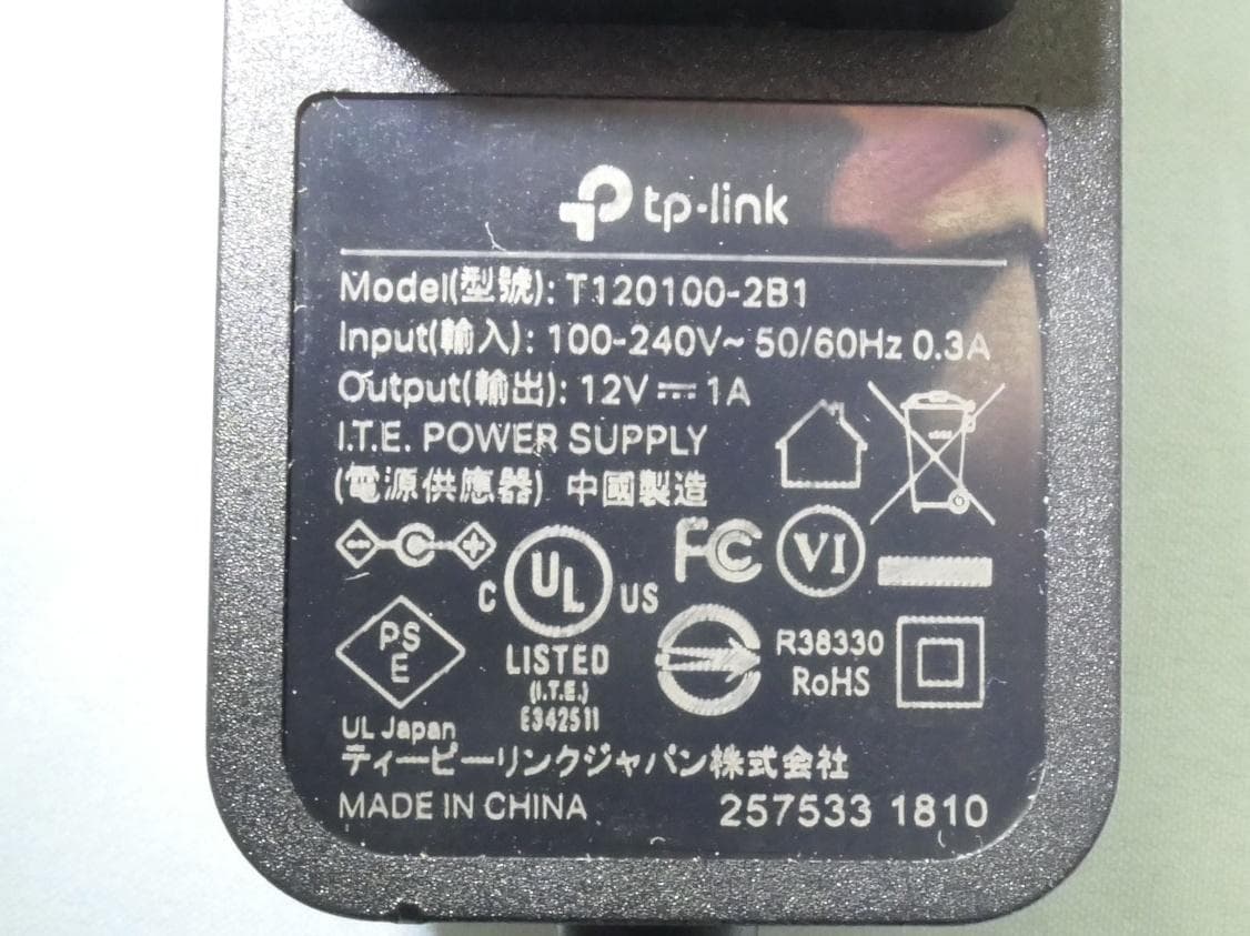
Click to zoom
Application Details
- Equipment Class
- NII - Unlicensed National Information Infrastructure TX
- Date of Grant
- Feb 04, 2026
- Application Purpose
- Original Equipment
- Equipment Note
- Outdoor Security Pan/Tilt Wi-Fi Camera
- Frequency Range
- 5180.00000000 - 5240.00000000
- Company
- TP-Link Systems Inc.
- Country
- United States
Documents & Files
Document Text
Text extracted from the exhibit documents filed with the FCC. Open a document above to read the original.
Users Manual
Outdoor Pan/Tilt Security Wi-Fi Camera Quick Start Guide *Images may differ from actual products. ©2025 TP-Link 7100001393 REV1.0.0 Set Up Your Camera 1 1. Download the App Download the Tapo app from the App Store or Google Play. Open the app and log in with your TP-Link ID. If you don't have an account, create one first. OR 2. Power Up Plug in the power adapter or connect to a PoE router via an Ethernet cable to power up your camera. OR power adapterPoE Ethernet cable 3. Set Up Tap the button > Add Device in the app and select your model. Follow the app instructions to set up your camera. My Home Mount Your Camera 2 Option 1: Wall Mount Stick the mounting template to the desired place. Drill 4 screw holes according to the template. 1. Drill Holes Route the cable through the grooves in the bracket. Make sure the rubber stopper remains at the end of the back groove to support the camera. 2. Route the Cable Use two bracket screws to affix the bracket and camera base. 4. Secure the Camera Align and slide the camera base onto the bracket from the outside in. 12 Rubber Stopper Option 2: Eave Mount Stick the mounting template to the desired place. Drill 2 screw holes according to the template. 1. Drill Holes 4. Secure the Camera Use two bracket screws to affix the bracket and camera base. Align and slide the camera base onto the bracket from the outside in. 12 Option 3: Pole Mount Route the cable through the grooves in the bracket. Make sure the rubber stopper remains at the end of the back groove to support the camera. 1. Route the Cable 3. Secure the Camera Use two bracket screws to affix the bracket and camera base. Align and slide the camera base onto the bracket from the outside in. 12 Install Waterproof Accessories 3 2. Install Waterproof Cable Attachments Install the waterproof cable attachments for the network interface. Make sure each part is securely attached and the waterproof rings are flush to keep out water. 1. Install the Waterproof Seal for Power Connectors Install the waterproof seal for the power connectors. Male Power Connector Waterproof Seal Female Power Connector When the Ethernet port connects to a network device 1) Route the network cable through the following components in order: fix nut, waterproof ring, and then the waterproof jacket. 2) Insert the waterproof ring into the waterproof jacket. 3) Fix the O-ring to the network interface of the camera and connect the network cables. 4) Attach the network interface with the waterproof jacket, then twist to lock. Rotate the fix nut to secure it to the waterproof jacket. Fix Nut Waterproof Ring O-ring Network Interface Waterproof Jacket When the Ethernet port does not connect to a network device Fix Nut Waterproof Ring + Plug Network Interface Waterproof Jacket O-ring 1) Insert the waterproof plug into the waterproof ring, then insert them into the waterproof jacket. 2) Fix the O-ring to the network interface of the camera. Attach the network interface with the waterproof jacket, then twist to lock. Rotate the fix nut to secure it to the waterproof jacket. *Pole-mounting Loop (Not Included) Insert 4 anchors into the holes and use the screws to affix the camera bracket over the anchors. 3. Install the Bracket Route the cable through the grooves in the bracket. Make sure the rubber stopper remains at the end of the upper groove to support the camera. 2. Route the Cable Insert 2 anchors into the holes and use the screws to affix the camera bracket over the anchors. 3. Install the Bracket 2. Install the Bracket Mount the bracket on the pole using two pole-mounting loops* (loop width ≤ 12 mm). Rubber Stopper Rubber Stopper Φ=6 mm (15/64 in.)Φ=6 mm (15/64 in.) Appearance Reset Button Open the silicone cover. While the camera is powered on, press and hold the RESET button to reset the camera. • Press and hold for 5 seconds: Reset Wi-Fi settings only • Press and hold for 10 seconds: Reset to factory settings microSD Card Slot Unscrew to remove the cover and insert a microSD card.* Initialize it on the Tapo app for local recording. *microSD card not included. Button Explanation 1 Microphone 2 White Light LEDs 3 Lens 4 Red-Blue Alarm Light 5 IR LEDs 6 Reset Button 7 microSD Card Slot 8 Speaker 9 DC Power Connector 10 PoE Ethernet Port Red-Blue Alarm Light Indication microSD Reset Reset microSD 22 1 3 44 5 76 8 910 Starting up Ready for Wi-Fi setup Connecting to Wi-Fi Connected to Wi-Fi or wired network Connected to the cloud Downloading/updating the firmware Camera resetting; Wi-Fi resetting Solid red Blinking red and blue slowly Blinking red slowly Blinking blue slowly Solid blue Blinking blue quickly Blinking red quickly Blinking blue 4 times microSD card inserted FCC compliance information statement Product Name: Outdoor Pan/Tilt Security Wi-Fi Camera Model Number: Tapo C566WB I.T.E. Power Supply T120100-2B1 Responsible Party: TP-Link Systems Inc. Address: 10 Mauchly, Irvine, CA 92618 Website: http://www.tp-link.com/us/ Tel: +1 626 333 0234 Fax: +1 909 527 6804 E-mail: [email protected] This equipment has been tested and found to comply with the limits for a Class B digital device, pursuant to part 15 of the FCC Rules. These limits are designed to provide reasonable protection against harmful interference in a residential installation. This equipment generates, uses and can radiate radio frequency energy and, if not installed and used in accordance with the instructions, may cause harmful interference to radio communications. However, there is no guarantee that interference will not occur in a particular installation. If this equipment does cause harmful interference to radio or television reception, which can be determined by turning the equipment off and on, the user is encouraged to try to correct the interference by one or more of the following measures: Reorient or relocate the receiving antenna. Increase the separation between the equipment and receiver. Connect the equipment into an outlet on a circuit different from th…
Text truncated - open the document above for the full version.
Internal Photos
Report No.: 2508TW0114-UI 1 of 5 Internal Photograph (1) EUT Photo (2) EUT Photo Report No.: 2508TW0114-UI 2 of 5 (3) EUT Photo (4) EUT Photo Report No.: 2508TW0114-UI 3 of 5 (5) EUT Photo (6) EUT Photo Report No.: 2508TW0114-UI 4 of 5 (7) EUT Photo (8) EUT Photo Report No.: 2508TW0114-UI 5 of 5 (9) EUT Photo (10) EUT Photo
Test Setup Photos
Report No.: 2508TW0114-UT 1 of 4 RF Test Photograph Description: Front View of Conducted Emission Test Setup Description: Back View of Conducted Emission Test Setup Report No.: 2508TW0114-UT 2 of 4 Description: Radiated Emission Test Setup for below 1GHz Description: Radiated Emission Test Setup for above 1GHz Report No.: 2508TW0114-UT 3 of 4 Description: Radiated Emission Test Setup for 18GHz~40GHz Description: Radiated Emission Test Setup for 9kHz~30MHz Report No.: 2508TW0114-UT 4 of 4 Description: Conducted Measurement Test Setup Description: DFS Test Setup
Test Report
Product Model: Tapo C566WB Manufacturer: TP-Link Systems Inc. Date: 2025.5.26 Checked By: Yang Junyu TP-Link Systems Inc. 10 Mauchly, Irvine, CA 92618 Index 1. Antenna Distribution ........................................................................................ 3 2. Electrical Characteristics ................................................................................ 3 3. S Parameter Test Data ..................................................................................... 4 4. Antenna Peak Gain........................................................................................... 5 5. Antenna Radiation Pattern .............................................................................. 5 Page 3 1. Antenna Distribution Tapo C566WB 2. Electrical Characteristics Ant1 Frequency 2400~2500 &5150~5895MHz Impedance 50Ohm Antenna Type Dipole Antenna Gain 3.06dBi@2400~2500MHz 3.40dBi@5150~5250MHz 3.40dBi@5250~5350MHz 3.06dBi@5470~5725MHz 3.04dBi@5725~5895MHz Radiation pattern Omni-Directional P/N NC Ant2 Frequency 2400~2500 &5150~5895MHz Impedance 50Ohm Antenna Type Dipole Antenna Gain 1.52dBi@2400~2500MHz 1.65dBi@5150~5250MHz 1.99dBi@5250~5350MHz 2.47dBi@5470~5725MHz 2.21dBi@5725~5895MHz Radiation pattern Omni-Directional P/N NC Page 4 3. S Parameter Test Data Ant1 Ant2 Page 5 4. Antenna Gain 4.1 Peak Gain Frequency 2.45GHz 2400~2500MHz 5.2GHz 5150~5250MHz 5.3GHz 5250~5350MHz 5.6GHz 5470~5725MHz Ant1 MaxGain(dBi) 3.06 3.40 3.40 3.06 Ant2 MaxGain(dBi) 1.52 1.65 1.99 2.47 Max Gain(dBi) 3.06 3.40 3.40 3.06 Frequency 5.8GHz 5725~5895MHz Ant1 MaxGain(dBi) 3.04 Ant2 MaxGain(dBi) 2.21 Max Gain(dBi) 3.04 5. Antenna Radiation Pattern Ant1 Page 6 Ant2 Page 7
Test Report
MRT Technology (Taiwan) Co., Ltd Report No.: 2508TW0114-U5 Phone: +86-512-66308358 Report Version: 1.0 Fax: +86-512-66308368 Issue Date: 2026-01-29 Web: www.mrt-cert.com Page Number: 1 of 25 FCC ID : 2BH7FC566WB APPLICANT : TP-Link Systems Inc. Application Type : Certification Product : Outdoor Security Pan/Tilt Wi-Fi Camera Model No. : Tapo C566WB Brand Name : tp-link FCC Classification : Unlicensed National Information Infrastructure (NII) FCC Rule Part(s) : Part 15.407 Test Procedure(s) : Master Device Client Device without radar detection Client Device with radar detection Received Date : August 27, 2025 Test Date : November 7, 2025 DFS MEASUREMENT REPORT Tested By : ( Peter Syu ) Reviewed By : ( Paddy Chen ) Approved By : ( Chenz Ker) The test results relate only to the samples tested. This equipment has been shown to be capable of compliance with the applicable technical standards as indicated in the measurement report and was tested in accordance with the measurement procedures specified in Part 15.407. Test results reported herein relate only to the item(s) tested. The test report shall not be reproduced except in full without the written approval of MRT Technology (Taiwan) Co., Ltd. Report No.: 2508TW0114-U5 Page Number: 2 of 25 Revision History Report No. Version Description Issue Date Note 2508TW0114-U5 1.0 Original Report 2026-01-29 Report No.: 2508TW0114-U5 Page Number: 3 of 25 CONTENTS Description Page 1. INTRODUCTION ..................................................................................................................... 5 1.1. Scope ........................................................................................................................... 5 1.2. MRT Test Location ....................................................................................................... 5 2. PRODUCT INFORMATION ..................................................................................................... 6 2.1. Equipment Description .................................................................................................. 6 2.2. Product Specification Subjective to this Report ............................................................. 6 2.3. Description of Available Antennas ................................................................................ 7 2.4. DFS Band Carrier Frequencies Operation .................................................................... 8 2.5. Test Mode .................................................................................................................... 8 3. DFS DETECTION THRESHOLDS AND RADAR TEST WAVEFORMS................................... 9 3.1. Applicability .................................................................................................................. 9 3.2. DFS Devices Requirements ........................................................................................ 10 3.3. DFS Detection Threshold Values ................................................................................. 11 3.4. Parameters of DFS Test Signals ................................................................................. 12 3.5. Conducted Test Setup ................................................................................................ 15 4. TEST EQUIPMENT CALIBRATION DATE ............................................................................ 16 5. TEST RESULT ...................................................................................................................... 17 5.1. Summary .................................................................................................................... 17 5.2. Radar Waveform Calibration ....................................................................................... 18 5.2.1. Calibration Setup ........................................................................................................ 18 5.2.2. Calibration Procedure ................................................................................................. 18 5.2.3. Cablibration Result ..................................................................................................... 19 5.3. Channel Loading Test Result ...................................................................................... 20 5.4. In-Service Monitoring for Channel Move Time, Channel Closing Transmission Time and Non-Occupancy Period Measurement ........................................................................................ 21 5.4.1. Test Limit .................................................................................................................... 21 5.4.2. Test Procedure Used .................................................................................................. 21 5.4.3. Test Result .................................................................................................................. 22 6. CONCLUSION ....................................................................................................................... 24 Appendix A : Setup Photograph ................................................................................................. 25 Appendix B : External Photograph ............................................................................................. 25 Appendix C : Internal Photograph .............................................................................................. 25 Report No.: 2508TW0114-U5 Page Number: 4 of 25 General Information Applicant TP-Link Systems Inc. Applicant Address 10 Mauchly, Irvine, CA 92618 Manufacturer TP-Link Systems Inc. Manufacturer Address 10 Mauchly, Irvine, CA 92618 Test Site MRT Technology (Taiwan) Co., Ltd Test Site Address No. 38, Fuxing Second Rd., Guishan Dist., Taoyuan City 333, Taiwan (R.O.C) MRT FCC Registration No. 291082 FCC Rule Part(s) Part 15.407 Test Facility / Accreditations 1. MRT facility is a FCC registered (Reg. No. 291082) test facility wi…
Text truncated - open the document above for the full version.
Test Report
Report No.: 2508TW0114-U4 Page Number: 303 of 516 EUT Outdoor Security Pan/Tilt Wi-Fi Camera Date of Test 2025-10-31 Factor DRH18-E Temp. / Humidity 20C /60% Polarity Vertical Site / Test Engineer AC2 / Marcus Test Mode 802.11ax-20MHz_TX_Band4_CH 165_ANT 1 Test Voltage AC 120V/60Hz No Frequency (MHz) Reading (dBuV) C.F (dB/m) Measurement (dBuV/m) Margin (dB) Limit (dBuV/m) Height (cm) Angle (deg) Remark (QP/PK/AV) 1 11650.000 38.48 7.22 45.70 -28.30 74.00 100 218 Peak 2 * 17475.000 37.73 7.41 45.14 -23.06 68.20 100 276 Peak Note: 1. " *", means this data is the worst emission level. 2. C.F (Correction Factor) = Antenna Factor (dB/m)+ Cable Loss (dB) – Preamplifier(dB). 3. Measurement (dBuV/m) = Reading(dBuV) + C.F (Correction Factor). 4. The emission levels of other frequencies are very lower than the limit and not show in test report. Report No.: 2508TW0114-U4 Page Number: 304 of 516 EUT Outdoor Security Pan/Tilt Wi-Fi Camera Date of Test 2025-10-31 Factor DRH18-E Temp. / Humidity 20C /60% Polarity Horizontal Site / Test Engineer AC2 / Marcus Test Mode 802.11ax-40MHz_TX_Band1_CH 38_ANT 1 Test Voltage AC 120V/60Hz No Frequency (MHz) Reading (dBuV) C.F (dB/m) Measurement (dBuV/m) Margin (dB) Limit (dBuV/m) Height (cm) Angle (deg) Remark (QP/PK/AV) 1 * 10380.000 38.03 6.83 44.86 -23.34 68.20 100 339 Peak 2 15570.000 38.33 8.66 46.99 -27.01 74.00 100 283 Peak Note: 1. " *", means this data is the worst emission level. 2. C.F (Correction Factor) = Antenna Factor (dB/m)+ Cable Loss (dB) – Preamplifier(dB). 3. Measurement (dBuV/m) = Reading(dBuV) + C.F (Correction Factor). 4. The emission levels of other frequencies are very lower than the limit and not show in test report. Report No.: 2508TW0114-U4 Page Number: 305 of 516 EUT Outdoor Security Pan/Tilt Wi-Fi Camera Date of Test 2025-10-31 Factor DRH18-E Temp. / Humidity 20C /60% Polarity Vertical Site / Test Engineer AC2 / Marcus Test Mode 802.11ax-40MHz_TX_Band1_CH 38_ANT 1 Test Voltage AC 120V/60Hz No Frequency (MHz) Reading (dBuV) C.F (dB/m) Measurement (dBuV/m) Margin (dB) Limit (dBuV/m) Height (cm) Angle (deg) Remark (QP/PK/AV) 1 * 10380.000 38.16 6.83 44.99 -23.21 68.20 100 156 Peak 2 15570.000 37.60 8.66 46.26 -27.74 74.00 100 108 Peak Note: 1. " *", means this data is the worst emission level. 2. C.F (Correction Factor) = Antenna Factor (dB/m)+ Cable Loss (dB) – Preamplifier(dB). 3. Measurement (dBuV/m) = Reading(dBuV) + C.F (Correction Factor). 4. The emission levels of other frequencies are very lower than the limit and not show in test report. Report No.: 2508TW0114-U4 Page Number: 306 of 516 EUT Outdoor Security Pan/Tilt Wi-Fi Camera Date of Test 2025-10-31 Factor DRH18-E Temp. / Humidity 20C /60% Polarity Horizontal Site / Test Engineer AC2 / Marcus Test Mode 802.11ax-40MHz_TX_Band1_CH 46_ANT 1 Test Voltage AC 120V/60Hz No Frequency (MHz) Reading (dBuV) C.F (dB/m) Measurement (dBuV/m) Margin (dB) Limit (dBuV/m) Height (cm) Angle (deg) Remark (QP/PK/AV) 1 * 10460.000 38.28 6.76 45.04 -23.16 68.20 100 80 Peak 2 15690.000 37.57 8.84 46.41 -27.59 74.00 100 95 Peak Note: 1. " *", means this data is the worst emission level. 2. C.F (Correction Factor) = Antenna Factor (dB/m)+ Cable Loss (dB) – Preamplifier(dB). 3. Measurement (dBuV/m) = Reading(dBuV) + C.F (Correction Factor). 4. The emission levels of other frequencies are very lower than the limit and not show in test report. Report No.: 2508TW0114-U4 Page Number: 307 of 516 EUT Outdoor Security Pan/Tilt Wi-Fi Camera Date of Test 2025-10-31 Factor DRH18-E Temp. / Humidity 20C /60% Polarity Vertical Site / Test Engineer AC2 / Marcus Test Mode 802.11ax-40MHz_TX_Band1_CH 46_ANT 1 Test Voltage AC 120V/60Hz No Frequency (MHz) Reading (dBuV) C.F (dB/m) Measurement (dBuV/m) Margin (dB) Limit (dBuV/m) Height (cm) Angle (deg) Remark (QP/PK/AV) 1 * 10460.000 38.10 6.76 44.85 -23.35 68.20 100 278 Peak 2 15690.000 38.40 8.84 47.24 -26.76 74.00 100 220 Peak Note: 1. " *", means this data is the worst emission level. 2. C.F (Correction Factor) = Antenna Factor (dB/m)+ Cable Loss (dB) – Preamplifier(dB). 3. Measurement (dBuV/m) = Reading(dBuV) + C.F (Correction Factor). 4. The emission levels of other frequencies are very lower than the limit and not show in test report. Report No.: 2508TW0114-U4 Page Number: 308 of 516 EUT Outdoor Security Pan/Tilt Wi-Fi Camera Date of Test 2025-10-31 Factor DRH18-E Temp. / Humidity 20C /60% Polarity Horizontal Site / Test Engineer AC2 / Marcus Test Mode 802.11ax-40MHz_TX_Band2_CH 54_ANT 1 Test Voltage AC 120V/60Hz No Frequency (MHz) Reading (dBuV) C.F (dB/m) Measurement (dBuV/m) Margin (dB) Limit (dBuV/m) Height (cm) Angle (deg) Remark (QP/PK/AV) 1 * 10540.000 37.95 6.68 44.62 -23.58 68.20 100 359 Peak 2 15810.000 37.44 9.05 46.49 -27.51 74.00 100 349 Peak Note: 1. " *", means this data is the worst emission level. 2. C.F (Correction Factor) = Antenna Factor (dB/m)+ Cable Loss (dB) – Preamplifier(dB). 3. Measurement (dBuV/m) = Reading(dBuV) + C.F (Correction Factor). 4. The emission levels of other frequencies are very lower than the limit and not show in test report. Report No.: 2508TW0114-U4 Page Number: 309 of 516 EUT Outdoor Security Pan/Tilt Wi-Fi Camera Date of Test 2025-10-31 Factor DRH18-E Temp. / Humidity 20C /60% Polarity Vertical Site / Test Engineer AC2 / Marcus Test Mode 802.11ax-40MHz_TX_Band2_CH 54_ANT 1 Test Voltage AC 120V/60Hz No Frequency (MHz) Reading (dBuV) C.F (dB/m) Measurement (dBuV/m) Margin (dB) Limit (dBuV/m) Height (cm) Angle (deg) Remark (QP/PK/AV) 1 * 10540.000 37.80 6.68 44.48 -23.72 68.20 100 157 Peak 2 15810.000 38.33 9.05 47.38 -26.62 74.00 100 181 Peak Note: 1. " *", means this data is the worst emission level. 2. C.F (Correction Factor) = Antenna Factor (dB/m)+ Cable Loss (dB) – Preamplifier(dB). 3. Measurement (dBuV/m) = Reading(dBuV) + C.F (Correction Factor). 4. The emission levels of other frequencies are very lower than the limit and not show in test report. Report No.: 2508TW0114-U4 Page Number: 310 of 516 EUT Outdo…
Text truncated - open the document above for the full version.
Test Report
Report No.: 2508TW0114-U4 Page Number: 72 of 516 Channel 100 (5500MHz) Channel 116 (5580MHz) Channel 140 (5700MHz) Channel 144 (5720MHz) Channel 149 (5745MHz) Channel 157 (5785MHz) Channel 165 (5825MHz) Report No.: 2508TW0114-U4 Page Number: 73 of 516 802.11ac-VHT40 Power Spectral Density - Ant 1 Channel 38 (5190MHz) Channel 46 (5230MHz) Channel 54 (5270MHz) Channel 62 (5310MHz) Channel 102 (5510MHz) Channel 110 (5550MHz) Channel 134 (5670MHz) Channel 142 (5710MHz) Report No.: 2508TW0114-U4 Page Number: 74 of 516 Channel 151 (5755MHz) Channel 159 (5795MHz) Report No.: 2508TW0114-U4 Page Number: 75 of 516 802.11ax-HE20 Power Spectral Density - Ant 1 Channel 36 (5180MHz) Channel 40 (5200MHz) Channel 48 (5240MHz) Channel 52 (5260MHz) Channel 60 (5300MHz) Channel 64 (5320MHz) Channel 100 (5500MHz) Channel 116 (5580MHz) Report No.: 2508TW0114-U4 Page Number: 76 of 516 Channel 140 (5700MHz) Channel 144 (5720MHz) Channel 149 (5745MHz) Channel 157 (5785MHz) Channel 165 (5825MHz) Report No.: 2508TW0114-U4 Page Number: 77 of 516 802.11ax-HE40 Power Spectral Density - Ant 1 Channel 38 (5190MHz) Channel 46 (5230MHz) Channel 54 (5270MHz) Channel 62 (5310MHz) Channel 102 (5510MHz) Channel 110 (5550MHz) Channel 134 (5670MHz) Channel 142 (5710MHz) Report No.: 2508TW0114-U4 Page Number: 78 of 516 Channel 151 (5755MHz) Channel 159 (5795MHz) Report No.: 2508TW0114-U4 Page Number: 79 of 516 7.7. Frequency Stability Measurement 7.7.1.Test Limit Manufactures of U-NII devices are responsible for ensuring frequency stability such that an emission is maintained within the band of operation under all conditions of normal operation as specified in the user’s manual. 7.7.2.Test Limit Frequency Stability Under Temperature Variations: The equipment under test was connected to an external AC or DC power supply and input rated voltage. RF output was connected to a frequency counter or spectrum analyzer via feed through attenuators. The EUT was placed inside the temperature chamber. Set the spectrum analyzer RBW low enough to obtain the desired frequency resolution and measure EUT 20°C operating frequency as reference frequency. Turn EUT off and set the chamber temperature to highest. After the temperature stabilized for approximately 30 minutes recorded the frequency. Repeat step measure with 10°C decreased per stage until the lowest temperature reached. Frequency Stability Under Voltage Variations: Set chamber temperature to 20°C. Use a variable AC power supply / DC power source to power the EUT and set the voltage to rated voltage. Set the spectrum analyzer RBW low enough to obtain the desired frequency resolution and recorded the frequency. Reduce the input voltage to specify extreme voltage variation (±15%) and endpoint, record the maximum frequency change. Report No.: 2508TW0114-U4 Page Number: 80 of 516 7.7.3.Test Setup 7.7.4.Test Result Grantee ensure that the product meets e-CFR Title 47 section 15.407(g) and KDB 789033 D02v02r01 frequency stability such that the emissions are maintained within the band of operation under all conditions of normal operation as specified in the user's manual. Report No.: 2508TW0114-U4 Page Number: 81 of 516 7.8. Radiated Spurious Emission Measurement 7.8.1.Test Limit All out of band emissions appearing in a restricted band as specified in Section 15.205 of the Title 47CFR must not exceed the limits shown in Table per Section 15.209. FCC Part 15 Subpart C Paragraph 15.209 Frequency [MHz] Field Strength [uV/m] Measured Distance [Meters] 0.009 - 0.490 2400/F (kHz) 300 0.490 - 1.705 24000/F (kHz) 30 1.705 - 30 30 30 30 - 88 100 3 88 - 216 150 3 216 - 960 200 3 Above 960 500 3 7.8.2.Test Procedure Used KDB 789033 D02v02r01- Section G 7.8.3.Test Setting Table 1 - RBW as a function of frequency Frequency RBW 9 ~ 150 kHz 200 ~ 300 Hz 0.15 ~ 30 MHz 9 ~ 10 kHz 30 ~ 1000 MHz 100 ~ 120 kHz >1000 MHz 1 MHz Report No.: 2508TW0114-U4 Page Number: 82 of 516 Quasi-Peak Measurements below 1GHz 1. Analyzer center frequency was set to the frequency of the radiated spurious emission of interest 2. Span was set greater than 1MHz 3. RBW = as specified in Table 1 4. Detector = CISPR quasi-peak 5. Sweep time = auto couple 6. Trace was allowed to stabilize Peak Measurements above 1GHz 1. Analyzer center frequency was set to the frequency of the radiated spurious emission of interest 2. RBW = 1MHz 3. VBW = 3MHz 4. Detector = peak 5. Sweep time = auto couple 6. Trace mode = max hold 7. Trace was allowed to stabilize Average Measurements above 1GHz (Method VB) 1. Analyzer center frequency was set to the frequency of the radiated spurious emission of interest 2. RBW = 1MHz 3. VBW;If the EUT is configured to transmit with duty cycle ≥ 98%, set VBW = 10 Hz. If the EUT duty cycle is < 98%, set VBW ≥ 1/T. T is the minimum transmission duration. 4. Detector = Peak 5. Sweep time = auto 6. Trace mode = max hold 7. Trace was allowed to stabilize Report No.: 2508TW0114-U4 Page Number: 83 of 516 7.8.4.Test Setup Below 1GHz Test Setup: Above 1GHz Test Setup: Report No.: 2508TW0114-U4 Page Number: 84 of 516 7.8.5.Test Result EUT Outdoor Security Pan/Tilt Wi-Fi Camera Date of Test 2025-10-29 Factor VULB 9162 Temp. / Humidity 20C /60% Polarity Horizontal Site / Test Engineer AC2 / Marcus Test Mode 802.11ac-20MHz_TX_Band1_CH 40_Ant 0 Test Voltage AC 120V/60Hz No Frequency (MHz) Reading (dBuV) C.F (dB/m) Measurement (dBuV/m) Margin (dB) Limit (dBuV/m) Height (cm) Angle (deg) Remark (QP/PK/AV) 1 42.370 4.97 20.47 25.43 -14.57 40.00 100 271 QP 2 71.668 8.10 15.75 23.85 -16.15 40.00 150 302 QP 3 * 108.026 18.81 18.61 37.42 -6.08 43.50 150 248 QP 4 208.868 17.66 18.15 35.81 -7.69 43.50 150 147 QP 5 610.868 10.46 26.94 37.40 -8.60 46.00 150 136 QP 6 813.322 8.05 30.02 38.07 -7.93 46.00 100 213 QP Note: 1. " *", means this data is the worst emission level. 2. C.F (Correction Factor) = Antenna Factor (dB/m) + Cable Loss (dB). 3. Measurement (dBuV/m) = Reading(dBuV) + C.F (Correction Factor). 4. The emission levels of other frequen…
Text truncated - open the document above for the full version.
Test Report
Report No.: 2508TW0114-U4 Page Number: 57 of 516 Product Outdoor Security Pan/Tilt Wi-Fi Camera Test Engineer Aby Test Site SR7 Test Date 2025/10/28~2025/11/5 Test Item Power Spectral Density (U-NII-3) Test Mode Data Rate/ MCS Ch. No. Freq. (MHz) PSD (Ant0) (dBm/510KHz) Duty Cycle (%) Ant0 PSD (dBm/ 510kHz) Limit (dBm/ 500kHz) Result 11a 6Mbps 149 5745 4.942 99.07% 4.983 ≤ 30.00 Pass 11a 6Mbps 157 5785 4.296 99.07% 4.337 ≤ 30.00 Pass 11a 6Mbps 165 5825 4.885 99.07% 4.926 ≤ 30.00 Pass 11ac-VHT20 MCS0 149 5745 4.169 99.17% 4.205 ≤ 30.00 Pass 11ac-VHT20 MCS0 157 5785 4.437 99.17% 4.473 ≤ 30.00 Pass 11ac-VHT20 MCS0 165 5825 4.679 99.17% 4.715 ≤ 30.00 Pass 11ac-VHT40 MCS0 151 5755 0.678 99.24% 0.711 ≤ 30.00 Pass 11ac-VHT40 MCS0 159 5795 0.676 99.24% 0.709 ≤ 30.00 Pass 11ax-HE20 MCS0 149 5745 4.532 99.22% 4.566 ≤ 30.00 Pass 11ax-HE20 MCS0 157 5785 4.195 99.22% 4.229 ≤ 30.00 Pass 11ax-HE20 MCS0 165 5825 4.162 99.22% 4.196 ≤ 30.00 Pass 11ax-HE40 MCS0 151 5755 0.869 99.12% 0.907 ≤ 30.00 Pass 11ax-HE40 MCS0 159 5795 1.511 99.12% 1.549 ≤ 30.00 Pass Note 1: The total PSD (dBm/510kHz) = PSD (dBm/510kHz) + 10*log (1/Duty Cycle). Report No.: 2508TW0114-U4 Page Number: 58 of 516 Test Mode Data Rate/ MCS Ch. No. Freq. (MHz) PSD (Ant1) (dBm/510KHz) Duty Cycle (%) Ant1 PSD (dBm/ 510kHz) Limit (dBm/ 500kHz) Result 11a 6Mbps 149 5745 6.211 99.07% 6.252 ≤ 30.00 Pass 11a 6Mbps 157 5785 6.433 99.07% 6.474 ≤ 30.00 Pass 11a 6Mbps 165 5825 6.352 99.07% 6.393 ≤ 30.00 Pass 11ac-VHT20 MCS0 149 5745 6.055 99.17% 6.091 ≤ 30.00 Pass 11ac-VHT20 MCS0 157 5785 5.794 99.17% 5.830 ≤ 30.00 Pass 11ac-VHT20 MCS0 165 5825 5.755 99.17% 5.791 ≤ 30.00 Pass 11ac-VHT40 MCS0 151 5755 2.218 99.24% 2.251 ≤ 30.00 Pass 11ac-VHT40 MCS0 159 5795 2.692 99.24% 2.725 ≤ 30.00 Pass 11ax-HE20 MCS0 149 5745 5.615 99.22% 5.649 ≤ 30.00 Pass 11ax-HE20 MCS0 157 5785 5.444 99.22% 5.478 ≤ 30.00 Pass 11ax-HE20 MCS0 165 5825 5.252 99.22% 5.286 ≤ 30.00 Pass 11ax-HE40 MCS0 151 5755 2.222 99.12% 2.260 ≤ 30.00 Pass 11ax-HE40 MCS0 159 5795 2.273 99.12% 2.311 ≤ 30.00 Pass Note 1: The total PSD (dBm/510kHz) = PSD (dBm/510kHz) + 10*log (1/Duty Cycle). Report No.: 2508TW0114-U4 Page Number: 59 of 516 802.11a Power Spectral Density - Ant 0 Channel 36 (5180MHz) Channel 40 (5200MHz) Channel 48 (5240MHz) Channel 52 (5260MHz) Channel 60 (5300MHz) Channel 64 (5320MHz) Channel 100 (5500MHz) Channel 116 (5580MHz) Report No.: 2508TW0114-U4 Page Number: 60 of 516 Channel 140 (5700MHz) Channel 144 (5720MHz) Channel 149 (5745MHz) Channel 157 (5785MHz) Channel 165 (5825MHz) Report No.: 2508TW0114-U4 Page Number: 61 of 516 802.11ac-VHT20 Power Spectral Density - Ant 0 Channel 36 (5180MHz) Channel 40 (5200MHz) Channel 48 (5240MHz) Channel 52 (5260MHz) Channel 60 (5300MHz) Channel 64 (5320MHz) Channel 100 (5500MHz) Channel 116 (5580MHz) Report No.: 2508TW0114-U4 Page Number: 62 of 516 Channel 140 (5700MHz) Channel 144 (5720MHz) Channel 149 (5745MHz) Channel 157 (5785MHz) Channel 165 (5825MHz) Report No.: 2508TW0114-U4 Page Number: 63 of 516 802.11ac-VHT40 Power Spectral Density - Ant 0 Channel 38 (5190MHz) Channel 46 (5230MHz) Channel 54 (5270MHz) Channel 62 (5310MHz) Channel 102 (5510MHz) Channel 110 (5550MHz) Channel 134 (5670MHz) Channel 142 (5710MHz) Report No.: 2508TW0114-U4 Page Number: 64 of 516 Channel 151 (5755MHz) Channel 159 (5795MHz) Report No.: 2508TW0114-U4 Page Number: 65 of 516 802.11ax-HE20 Power Spectral Density - Ant 0 Channel 3…
Text truncated - open the document above for the full version.
Contact Information
Applicant
Sarah Wang
[email protected]Fax: 6263330234
Technical Contact
TP-Link Systems Inc.Sarah Wang
10 Mauchly, Irvine, CA 92618 · Irvine, 92618 · United States
Test Firm
MRT Technology (Suzhou) Co., Ltd.Mr. Marlin Chen
Technical Specifications
| # | Rule Parts | Frequency Range | Power Output |
|---|---|---|---|
| 1 | 15E | 5.18 GHz - 5.24 GHz | 44.20 mW |
| 2 | 15E | 5.26 GHz - 5.32 GHz | 46.70 mW |
| 3 | 15E | 5.50 GHz - 5.72 GHz | 78.20 mW |
| 4 | 15E | 5.75 GHz - 5.83 GHz | 68.50 mW |