2BH7FC610Battery-Powered Pan/Tilt Security Camera
TP-Link Systems Inc.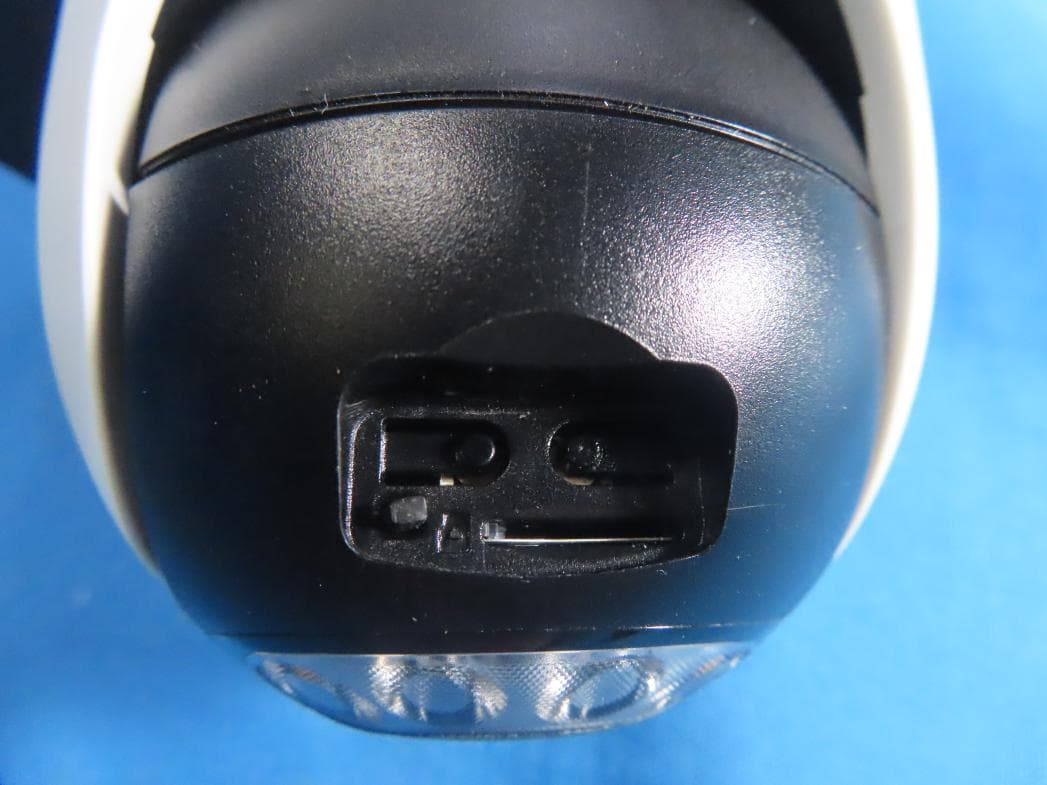
Click to zoom
Application Details
- Equipment Class
- DTS - Digital Transmission System
- Date of Grant
- Dec 24, 2025
- Application Purpose
- Original Equipment
- Equipment Note
- Battery-Powered Pan/Tilt Security Camera
- Frequency Range
- 2402.00000000 - 2480.00000000
- Company
- TP-Link Systems Inc.
- Country
- United States
Documents & Files
Document Text
Text extracted from the exhibit documents filed with the FCC. Open a document above to read the original.
Users Manual
2025/12/18https://www.tapo.com/en/document/52495/ https://www.tapo.com/en/document/52495/1/26 Installation and User Guide-Tapo C610/TC90/TCW90 About This Guide This guide provides a brief introduction to the Solar-Powered Pan/Tilt Security Camera Kit and the Tapo app, as well as regulatory information. Please note that features available in Tapo may vary by model and software version. Tapo availability may also vary by region. All images, steps, and descriptions in this guide are only examples and may not reect your actual Tapo Camera experience. Conventions In this guide, the following convention is used: More Info Specications can be found on the product page at https://www.tapo.com. Our Technical Support and troubleshooting information can be found at https://www.tapo.com/support/. The setup video can be found at https://www.tp-link.com/support/setup-video/#cloud-cameras. Introduction The Solar-Powered Pan/Tilt Security Camera oers 360° comprehensive protection with a 360° horizontal and 130° vertical viewing range, ensuring complete coverage and eliminating blind spots. You can set custom patrol points for dynamic, automated monitoring, all controlled through a single app that provides total control over premium features. With smart person detection, you receive instant alerts when a person is detected, signicantly reducing false alerts and unnecessary notications. Additionally, customizable activity zones allow you to monitor specic areas while blocking out zones that you wish to keep hidden. Wire-Free Design – Enjoy unparalleled security with the exibility to monitor any space—no outlets required. Smart Person Detection – Receive notications only when a person is detected, reducing false alerts and prolonging battery life. Convention Description Blue Key information appears in blue, including management page text such as menus, items, buttons and so on. Underline Hyperlinks are in blue and underlined. You can click to redirect to a website. NoteIgnoring this type of note might result in a malfunction or damage to the device. ▲ Top Menu searc 2025/12/18https://www.tapo.com/en/document/52495/ https://www.tapo.com/en/document/52495/2/26 2K 3MP Live View – Captures more details and delivers high-denition pictures with a 2304×1296 px resolution. IP65 Weatherproof – Performs well even in harsh environments with rain and dust, ideal for outdoor scenarios. Color Night Vision – Enhances your nighttime security by revealing vivid colors with the built-in dual spotlights. High-Eciency Solar Charging – Just 45 minutes§ of direct sunlight charges Tapo C610/TC90 for all-day use. No sun? No problem. The built-in battery provides power for up to 200 days.* *200-day battery life is based on Tapo laboratory tests with 300s of use per day. The time of use includes recording and watching live views. Actual battery life may vary due to device settings, usage, router specications, and environmental factors. Customizable Sound and Light Alarm – Record custom audio for alarms and adjust the brightness of the spotlights to suit your needs. Local* and Cloud** Storage – Save all your important moments to a microSD card* (Up to 512 GB) or subscribe to Tapo Care** for cloud serviceafter a free trial. *microSD card must be purchased separately. **Subscribe for cloud storage at https://www.tapo.com/tapocare/ Two-Way Audio – Enables communication through a built-in microphone and speaker. Appearance 1 IR LED 2 White Light LED 3 Status LED: It shows your camera status. 4 Lens: For capturing things within its view. 5 Motion Sensor 6 Microphone: For capturing your voice. 7 Reset Button: Open the cover to nd the Reset Button. While the camera is powered on, press and hold the RESET button to reset the camera. Press and hold for 5 seconds: Reset Wi-Fi while preserving the other. Press and hold for 10 seconds: Reset to factory settings. 8 On/O Power Button: Open the cover. Press and hold the On/O Button for 3 seconds to turn the camera on or o. 9 microSD card slot: Open the cover to nd the microSD card slot. Insert a microSD card (not included) and initialize it on the Tapo app for local recording. 10 USB Type-C Charging Port 11 Release Latch: Press two release latches to detach the camera from the bracket. ▲ Top Menusearc 2025/12/18https://www.tapo.com/en/document/52495/ https://www.tapo.com/en/document/52495/3/26 Status LED Indication LED StatusIndication Blinking amber quickly for 3 secondsPlugging in USB charger Solid redStarting up Blinking red and greenReady for setup Blinking red slowlyConnecting to Wi-Fi Solid amberConnected to Wi-Fi Solid greenConnected to the cloud Blinking red quicklyCamera resetting Blinking green quicklyCamera updating Set Up Your Camera Follow the steps below to get started with your new camera. Step 1. Download Tapo App Get the Tapo app from the App Store or Google Play, or by scanning the QR code below. Step 2. Log In Open the app, and log in with your TP-Link ID. If you don't have an account, create one rst. ▲ Top Menusearc 2025/12/18https://www.tapo.com/en/document/52495/ https://www.tapo.com/en/document/52495/4/26 Step 3. Add Your Camera Tap the + button, select Add Device in the app, and search for your model. Follow the app instructions to complete the setup. ▲ Top Menusearc 2025/12/18https://www.tapo.com/en/document/52495/ https://www.tapo.com/en/document/52495/5/26 Set Up Using Amazon Frustration-Free Setup What is Amazon Frustration-Free Setup? Note: Only Tapo C610 KIT supports Amazon frustration-free setup. Amazon Frustration-Free Setup can help connect and set up Tapo smart devices in fewer steps, without having to remember and re-enter your Wi-Fi password on each device. To use this feature, conrm the following: ● The new Tapo device supports Amazon FFS. ● The new Tapo device is purchased from Amazon. ● You have an Amazon FFS enabled Alexa device or router. ● You have saved your Wi-Fi information to Amazon by using Alexa echo. ● Your Tapo device and router a…
Text truncated - open the document above for the full version.
ID Label/Location Info
9.18±0.3mm9.18±0.3mm 12.31±0.3mm 15.16±0.5mm Battery-Powered Pan/Tilt Security Camera Model: TCW90 Input Rating: 5V 1A FCC ID: 2BH7FC610 Rainproof IP65 M AC : X X-X X-X X-X X-X X-X X S/N:XXXXXXXXXXXXX MADE IN VIETNAM US/1.6 This device complies with part 15 of the FCC Rules. Operation is subject to the following two conditions: (1) This device may not cause harmful interference, and (2) this device must accept any interference received, including interference that may cause undesired operation.
Test Setup Photos
Report No.:BTL-FCCP-2-2508C292A Report Version: R00 Page 30 of 92 11. EUT TEST PHOTO AC Power Line Conducted Emissions Test Photos Report No.:BTL-FCCP-2-2508C292A Report Version: R00 Page 31 of 92 Radiated Emissions Test Photos 9 kHz to 30 MHz Report No.:BTL-FCCP-2-2508C292A Report Version: R00 Page 32 of 92 Radiated Emissions Test Photos 30 MHz to 1 GHz Report No.:BTL-FCCP-2-2508C292A Report Version: R00 Page 33 of 92 Radiated Emissions Test Photos Band edge & Harmonic(1 GHz to 18 GHz) Report No.:BTL-FCCP-2-2508C292A Report Version: R00 Page 34 of 92 Radiated Emissions Test Photos Harmonic(18 GHz to 26.5 GHz) Report No.:BTL-FCCP-2-2508C292A Report Version: R00 Page 35 of 92 Conducted Test Photos
Test Report
Report No.:BTL-FCCP-2-2508C292A Report Version: R00 Page 88 of 92 Test Mode TX G Mode Reference Level-CH01 Reference Level-CH06 Reference Level-CH11 Bandedge-CH01 Bandedge-CH11 Harmonic-CH01 Harmonic-CH06 Harmonic-CH11 Report No.:BTL-FCCP-2-2508C292A Report Version: R00 Page 89 of 92 Test Mode TX N(HT20) Mode Reference Level-CH01 Reference Level-CH06 Reference Level-CH11 Bandedge-CH01 Bandedge-CH11 Harmonic-CH01 Harmonic-CH06 Harmonic-CH11 Report No.:BTL-FCCP-2-2508C292A Report Version: R00 Page 90 of 92 APPENDIX H - POWER SPECTRAL DENSITY Report No.:BTL-FCCP-2-2508C292A Report Version: R00 Page 91 of 92 Test Mode TX B Mode Channel Frequency (MHz) Power Spectral Density (dBm/3kHz) Max. Limit (dBm/3kHz) Result 01 2412 -1.24 8.00 Pass 06 2437 -1.34 8.00 Pass 11 2462 -1.70 8.00 Pass CH01 CH06 CH11 Test Mode TX G Mode Channel Frequency (MHz) Power Spectral Density (dBm/3kHz) Max. Limit (dBm/3kHz) Result 01 2412 -10.13 8.00 Pass 06 2437 -4.58 8.00 Pass 11 2462 -4.54 8.00 Pass CH01 CH06 CH11 Report No.:BTL-FCCP-2-2508C292A Report Version: R00 Page 92 of 92 Test Mode TX N(HT20) Mode Channel Frequency (MHz) Power Spectral Density (dBm/3kHz) Max. Limit (dBm/3kHz) Result 01 2412 -6.92 8.00 Pass 06 2437 -3.33 8.00 Pass 11 2462 -2.96 8.00 Pass CH01 CH06 CH11 End of Test Report
Test Report
Report No.:BTL-FCCP-2-2508C292A Report Version: R00 Page 1 of 92 FCC Radio Test Report FCC ID: 2BH7FC610 This report concerns: Original Grant Project No. : 2508C292A Equipment : Battery-Powered Pan/Tilt Security Camera Brand Name : tp-link Model Name : Tapo C610, TC90, TCW90 Applicant : TP-Link Systems Inc. Address : 10 Mauchly, Irvine, CA 92618 Manufacturer : TP-Link Systems Inc. Address : 10 Mauchly, Irvine, CA 92618 Date of Receipt : Aug. 07, 2025 Date of Test : Aug. 08, 2025 ~ Sep. 28, 2025 Issued Date : Dec. 18, 2025 Test Sample : Engineering Sample No.: DG920250807128 for radiate and ac power line conducted, DG920250807129 for others Standard(s) : FCC CFR Title 47, Part 15, Subpart C The above equipment has been tested and found compliance with the requirement of the relative standards by BTL Inc. (Dongguan) Prepared by : Te r r y Deng Approved by : Chay Cai No.3, Jinshagang 1st Road, Dalang, Dongguan, Guangdong People’s Republic of China. Te l : + 8 6-769-8318-3000 Web: www.newbtl.com Service mail: [email protected] Report No.:BTL-FCCP-2-2508C292A Report Version: R00 Page 2 of 92 Declaration BTL represents to the client that testing is done in accordance with standard procedures as applicable and that test instruments used has been calibrated with standards traceable to international standard(s) and/or national standard(s). BTL's reports apply only to the specific samples tested under conditions. It is manufacture’s responsibility to ensure that additional production units of this model are manufactured with the identical electrical and mechanical components. BTL assumes no responsibility for the data provided by the customer, any statements, inferences or generalizations drawn by the customer or others from the reports issued by BTL. The report must not be used by the client to claim product certification, approval, or endorsement by A2LA or any agency of the U.S. Government. This report is the confidential property of the client. As a mutual protection to the clients, the public and ourselves, the test report shall not be reproduced, except in full, without our written approval. BTL’s laboratory quality assurance procedures are in compliance with the ISO/IEC 17025: 2017 requirements, and accredited by the conformity assessment authorities listed in this test report. BTL is not responsible for the sampling stage, so the results only apply to the sample as received. The information, data and test plan are provided by manufacturer which may affect the validity of results, so it is manufacturer’s responsibility to ensure that the apparatus meets the essential requirements of applied standards and in all the possible configurations as representative of its intended use. Limitation For the use of the authority's logo is limited unless the Test Standard(s)/Scope(s)/Item(s) mentioned in this test report is (are) included in the conformity assessment authorities acceptance respective. Please note that the measurement uncertainty is provided for informational purpose only and are not use in determining the Pass/Fail results. Report No.:BTL-FCCP-2-2508C292A Report Version: R00 Page 3 of 92 Table of Contents Page REVISION HISTORY 6 1 . APPLICABLE STANDARDS 7 2 . SUMMARY OF TEST RESULTS 7 2.1 TEST FACILITY 8 2.2 MEASUREMENT UNCERTAINTY 8 2.3 TEST ENVIRONMENT CONDITIONS 9 3 . GENERAL INFORMATION 10 3.1 GENERAL DESCRIPTION OF EUT 10 3.2 DESCRIPTION OF TEST MODES 11 3.3 PARAMETERS OF TEST SOFTWARE 12 3.4 DUTY CYCLE 13 3.5 BLOCK DIAGRAM SHOWING THE CONFIGURATION OF SYSTEM TESTED 14 3.6 SUPPORT UNITS 14 3.7 CUSTOMER INFORMATION DESCRIPTION 15 4 . AC POWER LINE CONDUCTED EMISSIONS 16 4.1 LIMIT 16 4.2 TEST PROCEDURE 16 4.3 DEVIATION FROM TEST STANDARD 16 4.4 TEST SETUP 17 4.5 EUT OPERATION CONDITIONS 17 4.6 TEST RESULTS 17 5 . RADIATED EMISSIONS 18 5.1 LIMIT 18 5.2 TEST PROCEDURE 19 5.3 DEVIATION FROM TEST STANDARD 20 5.4 TEST SETUP 20 5.5 EUT OPERATION CONDITIONS 22 5.6 TEST RESULTS - 9 KHZ TO 30 MHZ 22 5.7 TEST RESULTS - 30 MHZ TO 1000 MHZ 22 5.8 TEST RESULTS - ABOVE 1000 MHZ 22 6 . BANDWIDTH 23 6.1 LIMIT 23 Report No.:BTL-FCCP-2-2508C292A Report Version: R00 Page 4 of 92 Table of Contents Page 6.2 TEST PROCEDURE 23 6.3 DEVIATION FROM STANDARD 23 6.4 TEST SETUP 23 6.5 EUT OPERATION CONDITIONS 23 6.6 TEST RESULTS 23 7 . MAXIMUM OUTPUT POWER 24 7.1 LIMIT 24 7.2 TEST PROCEDURE 24 7.3 DEVIATION FROM STANDARD 24 7.4 TEST SETUP 24 7.5 EUT OPERATION CONDITIONS 24 7.6 TEST RESULTS 24 8 . CONDUCTED SPURIOUS EMISSIONS 25 8.1 LIMIT 25 8.2 TEST PROCEDURE 25 8.3 DEVIATION FROM STANDARD 26 8.4 TEST SETUP 26 8.5 EUT OPERATION CONDITIONS 26 8.6 TEST RESULTS 26 9 . POWER SPECTRAL DENSITY 27 9.1 LIMIT 27 9.2 TEST PROCEDURE 27 9.3 DEVIATION FROM STANDARD 27 9.4 TEST SETUP 27 9.5 EUT OPERATION CONDITIONS 27 9.6 TEST RESULTS 27 10 . MEASUREMENT INSTRUMENTS LIST 28 11 . EUT TEST PHOTO 30 APPENDIX A - AC POWER LINE CONDUCTED EMISSIONS 36 APPENDIX B - RADIATED EMISSION - 9 KHZ TO 30 MHZ 39 APPENDIX C - RADIATED EMISSION - 30 MHZ TO 1000 MHZ 44 APPENDIX D - RADIATED EMISSION- ABOVE 1000 MHZ 47 Report No.:BTL-FCCP-2-2508C292A Report Version: R00 Page 5 of 92 Table of Contents Page APPENDIX E - BANDWIDTH 80 FAPPENDIX F - MAXIMUM OUTPUT POWER 84 APPENDIX G - CONDUCTED SPURIOUS EMISSIONS 86 APPENDIX H - POWER SPECTRAL DENSITY 90 Report No.:BTL-FCCP-2-2508C292A Report Version: R00 Page 6 of 92 REVISION HISTORY Report No. Version Description Issued Date Note BTL-FCCP-2-2508C292A R00 Original Report. Dec. 18, 2025 Valid Report No.:BTL-FCCP-2-2508C292A Report Version: R00 Page 7 of 92 1. APPLICABLE STANDARDS According to the specifications of the manufacturer, the EUT must comply with the requirements of the following standard: ANSI C63.10-2020 The following reference test guidance is not within the scope of accreditation of A2LA: KDB 558074 D01 15.247 Meas Guidance v05r02 2. SUMMARY OF TEST RESULTS Test procedures according to the technical standard(s): FCC CFR Title 47, Part 15, Subpart C Standard(s) Section Test Item Test Res…
Text truncated - open the document above for the full version.
Test Report
Report No.:BTL-FCCP-1-2508C292A Report Version: R00 Page 1 of 69 FCC Radio Test Report FCC ID: 2BH7FC610 This report concerns: Original Grant Project No. : 2508C292A Equipment : Battery-Powered Pan/Tilt Security Camera Brand Name : tp-link Model Name : Tapo C610, TC90, TCW90 Applicant : TP-Link Systems Inc. Address : 10 Mauchly, Irvine, CA 92618 Manufacturer : TP-Link Systems Inc. Address : 10 Mauchly, Irvine, CA 92618 Date of Receipt : Aug. 07, 2025 Date of Test : Aug. 08, 2025 ~ Sep. 28, 2025 Issued Date : Dec. 18, 2025 Test Sample : Engineering Sample No.: DG920250807128 for radiate and ac power line conducted, DG920250807129 for others Standard(s) : FCC CFR Title 47, Part 15, Subpart C The above equipment has been tested and found compliance with the requirement of the relative standards by BTL Inc. (Dongguan) Prepared by : Te r r y Deng Approved by : Chay Cai No.3, Jinshagang 1st Road, Dalang, Dongguan, Guangdong People’s Republic of China. Te l : + 8 6-769-8318-3000 Web: www.newbtl.com Service mail: [email protected] Report No.:BTL-FCCP-1-2508C292A Report Version: R00 Page 2 of 69 Declaration BTL represents to the client that testing is done in accordance with standard procedures as applicable and that test instruments used has been calibrated with standards traceable to international standard(s) and/or national standard(s). BTL's reports apply only to the specific samples tested under conditions. It is manufacture’s responsibility to ensure that additional production units of this model are manufactured with the identical electrical and mechanical components. BTL assumes no responsibility for the data provided by the customer, any statements, inferences or generalizations drawn by the customer or others from the reports issued by BTL. The report must not be used by the client to claim product certification, approval, or endorsement by A2LA or any agency of the U.S. Government. This report is the confidential property of the client. As a mutual protection to the clients, the public and ourselves, the test report shall not be reproduced, except in full, without our written approval. BTL’s laboratory quality assurance procedures are in compliance with the ISO/IEC 17025: 2017 requirements, and accredited by the conformity assessment authorities listed in this test report. BTL is not responsible for the sampling stage, so the results only apply to the sample as received. The information, data and test plan are provided by manufacturer which may affect the validity of results, so it is manufacturer’s responsibility to ensure that the apparatus meets the essential requirements of applied standards and in all the possible configurations as representative of its intended use. Limitation For the use of the authority's logo is limited unless the Test Standard(s)/Scope(s)/Item(s) mentioned in this test report is (are) included in the conformity assessment authorities acceptance respective. Please note that the measurement uncertainty is provided for informational purpose only and are not use in determining the Pass/Fail results. Report No.:BTL-FCCP-1-2508C292A Report Version: R00 Page 3 of 69 Table of Contents Page REVISION HISTORY 6 1 . APPLICABLE STANDARDS 7 2 . SUMMARY OF TEST RESULTS 7 2.1 TEST FACILITY 8 2.2 MEASUREMENT UNCERTAINTY 8 2.3 TEST ENVIRONMENT CONDITIONS 9 3 . GENERAL INFORMATION 10 3.1 GENERAL DESCRIPTION OF EUT 10 3.2 DESCRIPTION OF TEST MODES 12 3.3 PARAMETERS OF TEST SOFTWARE 13 3.4 BLOCK DIAGRAM SHOWING THE CONFIGURATION OF SYSTEM TESTED 14 3.5 SUPPORT UNITS 14 3.6 CUSTOMER INFORMATION DESCRIPTION 15 4 . AC POWER LINE CONDUCTED EMISSIONS 16 4.1 LIMIT 16 4.2 TEST PROCEDURE 16 4.3 DEVIATION FROM TEST STANDARD 16 4.4 TEST SETUP 17 4.5 EUT OPERATING CONDITIONS 17 4.6 TEST RESULTS 17 5 . RADIATED EMISSIONS 18 5.1 LIMIT 18 5.2 TEST PROCEDURE 19 5.3 DEVIATION FROM TEST STANDARD 20 5.4 TEST SETUP 20 5.5 EUT OPERATING CONDITIONS 22 5.6 TEST RESULT - 9 KHZ TO 30 MHZ 22 5.7 TEST RESULT - 30 MHZ TO 1000 MHZ 22 5.8 TEST RESULT - ABOVE 1000 MHZ 22 6 . BANDWIDTH 23 6.1 LIMIT 23 Report No.:BTL-FCCP-1-2508C292A Report Version: R00 Page 4 of 69 Table of Contents Page 6.2 TEST PROCEDURE 23 6.3 DEVIATION FROM STANDARD 23 6.4 TEST SETUP 23 6.5 EUT OPERATION CONDITIONS 23 6.6 TEST RESULTS 23 7 . MAXIMUM OUTPUT POWER 24 7.1 LIMIT 24 7.2 TEST PROCEDURE 24 7.3 DEVIATION FROM STANDARD 24 7.4 TEST SETUP 24 7.5 EUT OPERATION CONDITIONS 24 7.6 TEST RESULTS 24 8 . CONDUCTED SPURIOUS EMISSION 25 8.1 LIMIT 25 8.2 TEST PROCEDURE 25 8.3 DEVIATION FROM STANDARD 26 8.4 TEST SETUP 26 8.5 EUT OPERATION CONDITIONS 26 8.6 TEST RESULTS 26 9 . POWER SPECTRAL DENSITY 27 9.1 LIMIT 27 9.2 TEST PROCEDURE 27 9.3 DEVIATION FROM STANDARD 27 9.4 TEST SETUP 27 9.5 EUT OPERATION CONDITIONS 27 9.6 TEST RESULTS 27 10 . MEASUREMENT INSTRUMENTS LIST 28 11 . EUT TEST PHOTO 30 APPENDIX A - AC POWER LINE CONDUCTED EMISSIONS 36 APPENDIX B - RADIATED EMISSION - 9 KHZ TO 30 MHZ 39 APPENDIX C - RADIATED EMISSION - 30 MHZ TO 1000 MHZ 44 APPENDIX D - RADIATED EMISSION - ABOVE 1000 MHZ 47 Report No.:BTL-FCCP-1-2508C292A Report Version: R00 Page 5 of 69 Table of Contents Page APPENDIX E - BANDWIDTH 60 APPENDIX F - MAXIMUM OUTPUT POWER 63 APPENDIX G - CONDUCTED SPURIOUS EMISSION 65 APPENDIX H - POWER SPECTRAL DENSITY 68 Report No.:BTL-FCCP-1-2508C292A Report Version: R00 Page 6 of 69 REVISION HISTORY Report No. Version Description Issued Date Note BTL-FCCP-1-2508C292A R00 Original Report. Dec. 18, 2025 Valid Report No.:BTL-FCCP-1-2508C292A Report Version: R00 Page 7 of 69 1. APPLICABLE STANDARDS According to the specifications of the manufacturer, the EUT must comply with the requirements of the following standard: ANSI C63.10-2020 The following reference test guidance is not within the scope of accreditation of A2LA: KDB 558074 D01 15.247 Meas Guidance v05r02 2. SUMMARY OF TEST RESULTS Test procedures according to the technical standard(s): FCC CFR Title 47, Part 15, Subpart C Standard(s) Section Test Item Test Result Judgment Remark 15.…
Text truncated - open the document above for the full version.
Test Report
Product Model: Tapo C610 KIT Manufacturer: TP-Link Systems Inc. Test Date: 2025.06.13 Tested By: Shao Jinwei TP-Link Systems Inc. 10 Mauchly, Irvine, CA 92618 Index 1. Antenna Distribution ........................................................................................ 3 2. Electrical Characteristics ................................................................................ 3 3. Gain and Radiation Pattern ............................................................................. 4 3.1 Measurement Procedure ........................................................................................... 4 3.2 Test Setup ................................................................................................................. 5 3.3 S Parameter Test Data ............................................................................................. 6 3.4 Antenna Peak Gain ................................................................................................... 6 3.5 Antenna Radiation Pattern ........................................................................................ 7 Page 3 1. Antenna Distribution Tapo C610 KIT 2. Electrical Characteristics Ant1 Frequency 2400~2500 MHz Impedance 50Ohm Antenna Type Monopole Antenna Gain 0.00dBi@2400~2500MHz Radiation pattern Omni-Directional P/N Tapo C610 KIT_Ant1 Ant2 Frequency 2400~2500 MHz Impedance 50Ohm Antenna Type Monopole Antenna Gain 0.00dBi@2400~2500MHz Radiation pattern Omni-Directional P/N Tapo C610 KIT_Ant2 Page 4 3. Gain and Radiation Pattern 3.1 Measurement Procedure This measurement experiment adopted an antenna near-field measurement system, and the diagram of the measurement system was shown in Figure 3-1. The excitation signal was generated by the Keysight E5071C (300kHz-20GHz). Under the control of the central computer, the probe rotated in the θ direction, and the EUT rotated in the φ direction with the turntable. The probe sampling frame received and collected signals in the near-field range of the EUT. The software system which was controlled by the central computer completed the processing, output and display of the test data. Figure 3-1 The test site was a full anechoic chamber with a size of 3.0m×3.1m×2.97m, which was built by GTS Rayzone2800. All six surfaces of the anechoic chamber were pasted with absorbing materials. And the chamber was calibrated by the authoritative third-party lab every year. The antenna anechoic chamber measurement system adopted a 13-probe multi-probe system. The probe antennas were evenly distributed on the spherical surface surrounding the EUT, and theirs operating frequency was 600MHz~8.5GHz. During the measurement, the probe antennas were rotated in the θ direction under the control of the probe holder to sample the near-field data at the θ angle. At the same time, the EUT rotated with the turntable in the φ direction to sample the near field data at the φ angle. The sampling accuracy was 15°. The system diagram was shown in Figure 3-2. From the sampling results, the EUT's near-field test data of θ component, φ component and total component could be obtained. Page 5 Figure 3-2 Before the measurement, calibrated the vector network analyzer, and then connected the input end of each antenna to the output end of the vector network analyzer, and evenly the antennas to be measured. Test Equipment listed below: Equipments Model Manufacturer S/N Cali. Interval Cali. Due Date Chamber Rayzone2800 GTS(General Test System) MY5347043 5 12months 2026/01/15 Vector Network Analyzer E5071C Keysight MY46315238 24months 2026/03/13 GTS MaxSign100 Software V2.1 GTS(General Test System) / / / 3.2 Test Setup The test setup was shown in Figure 3-3, 3-4: Figure 3-3 Page 6 Figure 3-4 3.3 S Parameter Test Data Ant1 Ant2 3.4 Antenna Peak Gain Frequency 2.45GHz 2400~2500MHz Ant1 MaxGain(dBi) 0.00 Ant2 MaxGain(dBi) 0.00 Page 7 Ant1 Polarization/Φ (°)/θ(°) Theta/345/90 Ant2 Polarization/Φ (°)/θ(°) Theta/0/90 Max Gain(dBi) 0.00 3.5 Antenna Radiation Pattern Ant1 Ant2
RF Exposure Info
Report No.: BTL-FCCP-3-2508C292A Report Version: R00 Page 1 of 3 FCC RF EXPOSURE REPORT FCC ID: 2BH7FC610 Project No. : 2508C292A Equipment : Battery-Powered Pan/Tilt Security Camera Brand Name : tp-link Test Model : Tapo C610 Model Name : Tapo C610, TC90, TCW90 Hardware Version : 1.X Software Version : 1.0 Applicant : TP-Link Systems Inc. Address : 10 Mauchly, Irvine, CA 92618 Manufacturer : TP-Link Systems Inc. Address : 10 Mauchly, Irvine, CA 92618 Date of Receipt : Aug. 07, 2025 Date of Test : Aug. 08, 2025 ~ Sep. 28, 2025 Issued Date : Dec. 18, 2025 Test Sample : Engineering Sample No.: DG920250807129 Standard(s) : FCC Guidelines for Human Exposure IEEE C95.1 & FCC Part 2.1091 FCC Title 47 Part 2.1091 & KDB 447498 D01 v06 The above equipment has been tested and found compliance with the requirement of the relative standards by BTL Inc. (Dongguan) Prepared by : Te r r y Deng Approved by : Chay Cai No.3, Jinshagang 1st Road, Dalang, Dongguan, Guangdong People’s Republic of China. Te l : + 8 6-769-8318-3000 Web: www.newbtl.com Service mail: [email protected] Report No.: BTL-FCCP-3-2508C292A Report Version: R00 Page 2 of 3 REVISION HISTORY Report No. Version Description Issued Date Note BTL-FCCP-3-2508C292A R00 Original Report. Dec. 18, 2025 Valid Report No.: BTL-FCCP-3-2508C292A Report Version: R00 Page 3 of 3 1. MPE CALCULATION METHOD Calculation Method of RF Safety Distance: where: S = power density P = power input to the antenna G = power gain of the antenna in the direction of interest relative to an isotropic radiator R = distance to the center of radiation of the antenna 2. ANTENNA SPECIFICATION Ant. Manufacturer Model Name Antenna Type Connector Gain (dBi) 1 TP-Link Systems Inc. Tapo C610 KIT_Ant1 Monopole N/A 0 2 TP-Link Systems Inc. Tapo C610 KIT_Ant2 Monopole N/A 0 Note: (1) Smart antenna systems with two antennas, but operating in a (legacy) mo de where only one antennais used. (2)Ant.1 is the worst case and recorded. (3)The antenna gain is provided by the manufacturer. 3. CALCULATED RESULT For LE: 0.505.083.22110.00061.00000.001.00004.58 Max. Tune-up (dB) Max. Tune-up Power (dBm) Max. Tune-up Power (mW) Power Density (mW/cm²) Power Density Limit (mW/cm²) Antenna Gain (dBi) Antenna Gain (numeric) Max. Output Power (dBm) For 2.4GHz: 0.50 23.67232.80910.04631.0000 0.00 1.000023.17 Max. Tune-up (dB) Max. Tune-up Power (dBm) Max. Tune-up Power (mW) Power Density (mW/cm²) Power Density Limit (mW/cm²) Antenna Gain (dBi) Antenna Gain (numeric) Max. Output Power (dBm) Note: (1) The calculated distance is 20 cm. End of Test Report
Internal Photos
Project No.: 2508C292A Page 31 of 42 Project No.: 2508C292A Page 32 of 42 CMICR18650F9 Project No.: 2508C292A Page 33 of 42 LR1865HB Project No.: 2508C292A Page 34 of 42 Project No.: 2508C292A Page 35 of 42 Project No.: 2508C292A Page 36 of 42 Project No.: 2508C292A Page 37 of 42 Project No.: 2508C292A Page 38 of 42 Project No.: 2508C292A Page 39 of 42 Project No.: 2508C292A Page 40 of 42 Project No.: 2508C292A Page 41 of 42 ANT 2 ANT 1 Project No.: 2508C292A Page 42 of 42
Internal Photos
Project No.: 2508C292A Page 1 of 42 ATTACHMENT PHOTOGRAPHS OF EUT Project No.: 2508C292A Page 2 of 42 Tapo C610 Project No.: 2508C292A Page 7 of 42 Project No.: 2508C292A Page 8 of 42 CMICR18650F9 Project No.: 2508C292A Page 9 of 42 LR1865HB Project No.: 2508C292A Page 10 of 42 Project No.: 2508C292A Page 11 of 42 ANT 2 ANT 1 Project No.: 2508C292A Page 12 of 42 Project No.: 2508C292A Page 13 of 42 Project No.: 2508C292A Page 14 of 42 Project No.: 2508C292A Page 15 of 42 Project No.: 2508C292A Page 16 of 42 Project No.: 2508C292A Page 17 of 42 Project No.: 2508C292A Page 18 of 42 Project No.: 2508C292A Page 19 of 42 Project No.: 2508C292A Page 20 of 42 Project No.: 2508C292A Page 21 of 42 Project No.: 2508C292A Page 22 of 42 Project No.: 2508C292A Page 23 of 42 Project No.: 2508C292A Page 24 of 42 TC90 Project No.: 2508C292A Page 29 of 42 Project No.: 2508C292A Page 30 of 42
Attestation Statements
TP-Link Systems Inc. CERTIFICATIONS CONCERNING “COVERED” EQUIPMENT Date:2025-12-16 Federal Communications Commission Authorization and Evaluation Division 7435 Oakland Mills Road Columbia, Maryland 21046 FCC ID: 2BH7FC610 To Whom It May Concern: As required by section 2.911(d)(5)(i), [TP-Link Systems Inc.] (“the applicant”) certifies that the equipment for which authorization is sought is not “covered” equipment prohibited from receiving an equipment authorization pursuant to section 2.903 of the FCC rules. TP-Link Systems Inc. certifies that the equipment for which authorization is sought does not include cybersecurity or anti-virus software produced or provided by Kaspersky Lab, Inc. or any of its successors and assignees, including equipment with integrated Kaspersky Lab, Inc. (or any of its successors and assignees) cybersecurity or anti-virus software pursuant to DA-24-886 and KDB 986446 D01 Covered Equipment Guidance section B(2a). As required by section 2.911(d)(5)(ii), [TP-Link Systems Inc.] (“the applicant”) certifies that, as of the date of the filing of the application, the applicant [is not] identified on the Covered List (as a specifically named entity or any of its subsidiaries or affiliates) as an entity producing “covered” equipment. Thank you for your attention to this matter. Sincerely yours, Signature Printed Name: Sarah Wang Company: TP-Link Systems Inc. Job Title: Regulatory Compliance Manager Email: [email protected] Telephone: 6263330234 TP-Link Systems Inc.
ID Label/Location Info
9.01±0.3mm9.01±0.3mm …
Text truncated - open the document above for the full version.
Contact Information
Applicant
Sarah Wang
[email protected]Fax: 6263330234
Technical Contact
TP-Link Systems Inc.Sarah Wang
10 Mauchly, Irvine, CA 92618 · Irvine, 92618 · United States
Test Firm
BTL Inc. (Dongguan)Sophia Huang
Technical Specifications
| # | Rule Parts | Frequency Range | Power Output |
|---|---|---|---|
| 1 | 15C | 2.40 GHz - 2.48 GHz | 2.90 mW |
| 2 | 15C | 2.41 GHz - 2.46 GHz | 207.50 mW |