2BH7FC675DBattery-Powered Dual-Lens Pan/Tilt Security Camera
TP-Link Systems Inc.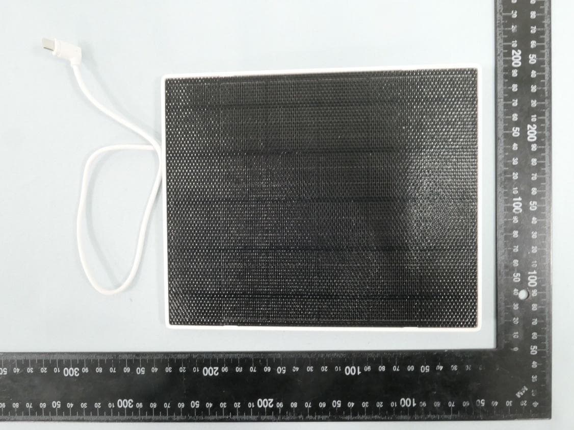
Click to zoom
Application Details
- Equipment Class
- DTS - Digital Transmission System
- Date of Grant
- Feb 13, 2026
- Application Purpose
- Original Equipment
- Equipment Note
- Battery-Powered Dual-Lens Pan/Tilt Security Camera
- Frequency Range
- 2402.00000000 - 2480.00000000
- Company
- TP-Link Systems Inc.
- Country
- United States
Documents & Files
Document Text
Text extracted from the exhibit documents filed with the FCC. Open a document above to read the original.
Users Manual
Solar-Powered Dual-Lens Pan/Tilt Security Camera Kit Quick Start Guide *Images may differ from actual products.©2025 TP-Link 7100001722 REV1.0.0 Note: 1. Peel off the film from the camera before use. 2. Prior to mounting your camera, fully charge the battery using the included USB cable. (Some 3rd party cables may result in slow or failed charging.) 3. Warning: Do not tear off the silicone part by force as it may affect the waterproof and dustproof performance. 4. When plugged in, the LED will quickly blink amber quickly for 3 seconds. If not, make sure power is running and check your connection. 5. Keep the ports firmly covered when not in use to ensure the waterproof and dustproof performance. 6. The camera may not power up after falling. Plug in the USB charger to power it on again. 7. Check the battery status on the Tapo app after setup. The battery comes partially charged. We recommend that you fully charge the battery before use. A full charge can take up to 6 hours. Charge the Battery 1 1.Get the Tapo app from the App Store or Google Play, and log in. 2.Open the cover, then press and hold the power button (right) on your camera for about 3 seconds to turn it on. Open the Tapo app, tap the button in the app, and select your model. Then follow the app instructions to set up your camera. Set Up the Camera 2 My Home OR 3.Do not place the camera upside down. 1.Avoid placing behind windows/glass. Windows and glass can block the motion sensor of your camera, preventing motion detection. 2.Choose your mounting location. Proper mounting of your camera will prevent issues such as frequent false alerts. • Avoid pointing the camera directly at swaying trees. • Avoid pointing the camera in high traffic areas unless that is the desired monitoring location. • Avoid pointing the camera directly at streetlights or sunlight. 5.Mounting your camera at an angle so movement crosses the lens’s field of view will provide more accurate motion detection and and AI detection. Camera Mounting Tips 3 6.For optimal detection performance, we recommend mounting the camera 8 ft (2.5 m) above the ground. 4.For optimal results, keep the motion sensor level, tilt the camera's wide-angle lens down at an angle of about 15°, and tilt the telephoto lens down at an angle of about 20°. Mount the Camera 5 1. Drill Holes Place the mounting template sticker to a solid and level wall surface. Drill four holes (Wall Mount) or two holes (Eave Mount) according to the template. 3. Install the Camera Slide the camera onto the camera bracket until it clicks into place. 2. Secure the Bracket Insert four anchors (Wall Mount) or two anchors (Eave Mount) into the holes and use the screws to affix the camera bracket over the anchors. 4. Adjust the Camera Angle & Antennas 1) Tilt the camera's wide-angle lens down at an angle of about 15°, and tilt the telephoto lens down at an angle of about 20°. 2) For optimal signal, adjust the antennas vertically upwards. PIR Detection Zone (Default Wake-up Sensitivity*) PIR Detection Zone (Highest Wake-up Sensitivity*) Camera Field of View + Power Button 26 ft / 8 m (Default Wake-up Sensitivity) 32 ft / 10 m (Highest Wake-up Sensitivity) Height: 8 ft / 2.5 m 22 ft / 7 m (Default Wake-up Sensitivity) 29 ft / 9 m (Highest Wake-up Sensitivity) Height: 8 ft / 2.5 m *You can adjust the sensitivity in Camera Settings > Detection > Wake-up Sensitivity. Wide-Angle Lens Telephoto Lens 5V 2A USB Charger (Not Included) 20° 15° Φ=6 mm (15/64 in.) Wall Mount: 1-4 Eave Mount: 1-2 or 3-4 The position and tilt angle of the solar panel greatly affects solar efficiency. 1.Choose a location where the solar panel receives the most sunlight throughout the year. Regularly wipe the panel to remove dust and debris. 2.Position the panel south-facing in the Northern Hemisphere or north-facing in the Southern Hemisphere. The recommended tilt angle between the panel and the horizontal ground is 35° ~ 45°. Solar Panel Mounting Tips 4 *Do not mount facing the direction of movement. Flip the page over to continue. Wall MountEave Mount 20° 15° Wall/Eave Mount Mount the Camera 5 For Solar Panel: • Keep the device away from fire or hot environments. DO NOT immerse in water or any other liquid. • Do not attempt to disassemble, repair, or modify the device. If you need service, please contact us. TP-Link hereby declares that the solar panel is in compliance with the essential requirements and other relevant provisions of directives 2014/30/EU, 2014/35/EU, 2011/65/EU and (EU)2015/863. The original EU declaration of conformity may be found at https://www.tapo.com/en/support/ce/ TP-Link hereby declares that the solar panel is in compliance with the essential requirements and other relevant provisions of the Electromagnetic Compatibility Regulations 2016 and Electrical Equipment (Safety) Regulations 2016. The original UK declaration of conformity may be found at https://www.tapo.com/support/ukca/ For Camera: • This equipment can be powered only by equipments that comply with Power Source Class 2 (PS2) or Limited Power Source (LPS) defined in the standard of IEC 62368-1. • Do not use damaged charger or USB cable to charge the device. • Do not use any other chargers than those recommended. • Do not use the device where wireless devices are not allowed. • Adapter shall be easily accessible. • Use only power supplies which are provided by manufacturer and in the original packing of this product. If you have any questions, please don't hesitate to contact us. • Keep the device away from fire or hot environments. DO NOT immerse in water or any other liquid. • Do not disassemble, repair or modify the product. • Do not place near automatically controlled devices such as fire alarms. Radio waves emitted from this product may cause such devices to malfunction resulting in an accident. • Observe restrictions on using wireless products in fuel depots, chemical plants or when blasting operations are in progress. • Do not use liquid to clean the produc…
Text truncated - open the document above for the full version.
Internal Photos
Report No.: 2512TW0115-UI 1 of 9 Internal Photograph (1) EUT Photo (2) EUT Photo Report No.: 2512TW0115-UI 2 of 9 (3) EUT Photo (4) EUT Photo Report No.: 2512TW0115-UI 3 of 9 (5) EUT Photo (6) EUT Photo Report No.: 2512TW0115-UI 4 of 9 (7) EUT Photo (8) EUT Photo Report No.: 2512TW0115-UI 5 of 9 (9) EUT Photo (10) EUT Photo Report No.: 2512TW0115-UI 6 of 9 (11) EUT Photo (12) EUT Photo Report No.: 2512TW0115-UI 7 of 9 (13) EUT Photo (14) EUT Photo Report No.: 2512TW0115-UI 8 of 9 (15) EUT Photo (16) EUT Photo Report No.: 2512TW0115-UI 9 of 9 (17) EUT Photo (18) EUT Photo
Test Setup Photos
Report No.: 2512TW0115-UT 1 of 8 BLE Test Photograph Description: Front View of Conducted Emission Test Setup Description: Back View of Conducted Emission Test Setup Report No.: 2512TW0115-UT 2 of 8 Description: Radiated Emission Test Setup for below 1GHz Description: Radiated Emission Test Setup for above 1GHz Report No.: 2512TW0115-UT 3 of 8 Description: Radiated Emission Test Setup for 18GHz~40GHz Description: Radiated Emission Test Setup for 9kHz~30MHz Report No.: 2512TW0115-UT 4 of 8 Description: Conducted Measurement Test Setup Description: DFS Test Setup Report No.: 2512TW0115-UT 5 of 8 Wi-Fi 2.4G & 5G Test Photograph Description: Front View of Conducted Emission Test Setup Description: Back View of Conducted Emission Test Setup Report No.: 2512TW0115-UT 6 of 8 Description: Radiated Emission Test Setup for below 1GHz Description: Radiated Emission Test Setup for above 1GHz Report No.: 2512TW0115-UT 7 of 8 Description: Radiated Emission Test Setup for 18GHz~40GHz Description: Radiated Emission Test Setup for 9kHz~30MHz Report No.: 2512TW0115-UT 8 of 8 Description: Conducted Measurement Test Setup Description: DFS Test Setup
Test Report
Product Model: Tapo C675D(US) 1.6/Tapo C675D KIT(US) 1.6 Manufacturer: TP-Link Systems Inc. Test Date: 2025.11.28 Tested By: Wu Jian TP-Link Systems Inc. 10 Mauchly, Irvine, CA 92618 Index 1. Antenna Distribution ........................................................................................ 3 2. Electrical Characteristics ................................................................................ 3 3. Gain and Radiation Pattern ............................................................................. 5 3.1 Measurement Procedure......................................................................................... 5 3.2 Test Setup .............................................................................................................. 6 3.3 S Parameter Test Data ........................................................................................... 7 3.4 Antenna Peak Gain ................................................................................................. 9 3.5 Antenna Radiation Pattern ...................................................................................... 9 4. Test Pattern .................................................................................................... 12 Page 3 1. Antenna Distribution Tapo C675D 2. Electrical Characteristics Ant1 Frequency 2400~2500MHz&5150~5850MHz Impedance 50Ohm Antenna Type Dipole Antenna Gain 1.96dBi@2400~2500MHz 2.96dBi@5150~5850MHz Radiation pattern Omni-Directional P/N Ant2 Frequency 2400~2500MHz&5150~5850MHz Impedance 50Ohm Antenna Type Dipole Antenna Gain 1.98dBi@2400~2500MHz 3.00dBi@5150~5850MHz Radiation pattern Omni-Directional Page 4 P/N Ant3(BLE) Frequency 2400~2500MHz Impedance 50Ohm Antenna Type Dipole Antenna Gain 1.98dBi@2400~2500MHz Radiation pattern Omni-Directional P/N Page 5 Gain and Radiation Pattern 2.1 Measurement Procedure This measurement experiment adopted an antenna near-field measurement system, and the diagram of the measurement system was shown in Figure 3-1. The excitation signal was generated by the Keysight E5071C (300kHz-20GHz). Under the control of the central computer, the probe rotated in the θ direction, and the EUT rotated in the φ direction with the turntable. The probe sampling frame received and collected signals in the near-field range of the EUT. The software system which was controlled by the central computer completed the processing, output and display of the test data. Figure 0-1 The test site was a full anechoic chamber with a size of 3.0m×3.1m×2.97m, which was built by GTS Rayzone2800. All six surfaces of the anechoic chamber were pasted with absorbing materials. And the chamber was calibrated by the authoritative third-party lab every year. The antenna anechoic chamber measurement system adopted a 13-probe multi-probe system. The probe antennas were evenly distributed on the spherical surface surrounding the EUT, and theirs operating frequency was 600MHz~8.5GHz. During the measurement, the probe antennas were rotated in the θ direction under the control of the probe holder to sample the near-field data at the θ angle. At the same time, the EUT rotated with the turntable in the φ direction to sample the near field data at the φ angle. The sampling accuracy was 15°. The system diagram was shown in Figure 3-2. From the sampling results, the EUT's near-field test data of θ component, φ component and total component could be obtained. Page 6 Figure 0-2 Before the measurement, calibrated the vector network analyzer, and then connected the input end of each antenna to the output end of the vector network analyzer, and evenly the antennas to be measured. Test Equipment listed below: Equipments Model Manufacturer S/N Cali. Interval Cali. Due Date Chamber Rayzone2800 GTS(General Test System) MY5347043 5 12months 2026/01/15 Vector Network Analyzer E5071C Keysight MY46315238 24months 2026/03/13 GTS MaxSign100 Software V2.1 GTS(General Test System) / / / 2.2 Test Setup The test setup was shown in Figure 3-3, 3-4: Figure 0-3 Page 7 Figure 0-4 2.3 S Parameter Test Data Ant1 Page 8 Ant2 Ant3 Page 9 2.4 Antenna Peak Gain Frequency 2.45GHz 2400~2500MHz 5.2GHz 5150~5250MHz 5.3GHz 5250~5350MHz 5.6GHz 5470~5725MHz 5.8GHz 5725~5895MHz Ant1 MaxGain(dBi) 1.96 2.72 2.72 2.96 2.96 Ant1 Polarization/ Φ(°)/θ(°) Theta/180/75 Theta/180/90 Theta/180/90 Theta/180/105 Theta/180/105 Ant2 MaxGain(dBi) 1.98 3.00 2.96 2.65 1.83 Ant2 Polarization/ Φ(°)/θ(°) Theta/15/75 Theta/15/105 Theta/15/105 Theta/0/105 Theta/345/75 Ant3 MaxGain(dBi) 1.98 Ant3 Polarization/ Φ(°)/θ(°) Theta/0/165 Max Gain(dBi) 1.98 3.00 2.96 2.96 2.96 2.5 Antenna Radiation Pattern Ant1 Page 10 Ant2 Page 11 Ant3 Page 12 3. Test Pattern ANT1 Freq 2500 Phi\Thet a 0 15 30 45 60 75 90 105 120 135 150 165 180 0 -31.6 -11.81 -6.58 -6.71 -12.65 -3.85 -2.64 -4.81 -8.28 -9.07 -2.9 -4.07 -11.1 15 -26.57 -12.2 -6.34 -5.33 -14.45 -8.7 -4.22 -3.22 -4.35 -5.86 -5.44 -5.93 -11.1 30 -26.59 -12.8 -5.86 -3.23 -8.5 -7.9 -4.49 -2.46 -2.82 -1.81 -2.43 -4.85 -11.1 45 -27.93 -14.5 -5.93 -3.71 -4.89 -5.66 -4.2 -2.37 -2.93 -1.36 -1.18 -2.87 -11.1 60 -25.77 -16.29 -7.93 -5.6 -5.25 -4.75 -4.7 -2.46 -1.83 -5.63 -6.08 -2.33 -11.1 75 -25.41 -19.41 -14.03 -8.76 -8.25 -4.21 -4.03 -3.23 -4.15 -2.8 -8.44 -2.88 -11.1 90 -24.14 -23.01 -20 -18.94 -17.86 -8.22 -7.98 -7.64 -8.87 -6.34 -8.21 -3.55 -11.1 105 -24.62 -20.22 -9.67 -8.92 -8.87 -7.17 -4.66 -4.22 -4.74 -8.51 -10.76 -3.53 -11.1 120 -25.54 -15.69 -5.77 -3.1 -2.37 -2.43 -2.06 -0.57 -1.92 -7.48 -9.54 -3.18 -11.1 135 -27.76 -12.87 -4.05 -0.42 0.02 -0.61 -2.46 -2.47 -3.13 -5.68 -4.89 -3.96 -11.1 150 -26.32 -11.33 -4.06 0.84 0.26 0.83 -0.48 -2.05 -2.22 -0.97 -3.81 -5.49 -11.1 165 -25.76 -10.77 -4.06 0.83 0.79 1.33 -0.03 -1.94 -3.43 -1.86 -7.3 -6.57 -11.1 180 -24.39 -11.08 -3.96 0.2 0.98 1.96 -0.3 -0.24 -3.16 -2.89 -7.94 -5.08 -11.1 195 -25.58 -12.52 -5.26 -0.33 0.18 1.21 0.58 -1.11 -5 -2.28 -5.35 -3.72 -11.1 210 -27.12 -15.15 -8.22 -2.29 -0.91 0.85 -1.35 -1.91 -3.17 -7.9 -8.74 -3.88 -11.1 225 -29.…
Text truncated - open the document above for the full version.
Test Report
Report No.: 2512TW0115-U3 Page Number: 207 of 219 EUT Battery-Powered Dual-Lens Pan/Tilt Security Camera Date of Test 2026-01-21 Factor DRH18-E Temp. / Humidity 20C /62% Polarity Vertical Site / Test Engineer AC2 / Stanley Test Mode 802.11n-20MHz_TX_CH 10_ANT 2 Test Voltage AC 120V/60Hz No Frequency (MHz) Reading (dBuV) C.F (dB/m) Measurement (dBuV/m) Margin (dB) Limit (dBuV/m) Height (cm) Angle (deg) Remark (QP/PK/AV) 1 2453.380 83.21 31.26 114.48 N/A N/A 193 300 Peak 2 2483.500 40.76 31.37 72.13 -1.87 74.00 193 300 Peak 3 * 2484.400 42.42 31.37 73.79 -0.21 74.00 193 300 Peak Note: 1. " *", means this data is the worst emission level. 2. C.F (Correction Factor) = Antenna Factor (dB/m) + Cable Loss (dB). 3. Measurement (dBuV/m) = Reading(dBuV) + C.F (Correction Factor). 4. The emission levels of other frequencies are very lower than the limit and not show in test report. Report No.: 2512TW0115-U3 Page Number: 208 of 219 EUT Battery-Powered Dual-Lens Pan/Tilt Security Camera Date of Test 2026-01-21 Factor DRH18-E Temp. / Humidity 20C /62% Polarity Vertical Site / Test Engineer AC2 / Stanley Test Mode 802.11n-20MHz_TX_CH 10_ANT 2 Test Voltage AC 120V/60Hz No Frequency (MHz) Reading (dBuV) C.F (dB/m) Measurement (dBuV/m) Margin (dB) Limit (dBuV/m) Height (cm) Angle (deg) Remark (QP/PK/AV) 1 2453.920 73.08 31.26 104.34 N/A N/A 193 300 Average 2 * 2483.500 21.61 31.37 52.97 -1.03 54.00 193 300 Average 3 2484.520 21.12 31.37 52.49 -1.51 54.00 193 300 Average Note: 1. " *", means this data is the worst emission level. 2. C.F (Correction Factor) = Antenna Factor (dB/m) + Cable Loss (dB). 3. Measurement (dBuV/m) = Reading(dBuV) + C.F (Correction Factor). 4. The emission levels of other frequencies are very lower than the limit and not show in test report. Report No.: 2512TW0115-U3 Page Number: 209 of 219 EUT Battery-Powered Dual-Lens Pan/Tilt Security Camera Date of Test 2026-01-21 Factor DRH18-E Temp. / Humidity 20C /62% Polarity Horizontal Site / Test Engineer AC2 / Stanley Test Mode 802.11n-20MHz_TX_CH 11_ANT 2 Test Voltage AC 120V/60Hz No Frequency (MHz) Reading (dBuV) C.F (dB/m) Measurement (dBuV/m) Margin (dB) Limit (dBuV/m) Height (cm) Angle (deg) Remark (QP/PK/AV) 1 2463.640 75.91 30.90 106.82 N/A N/A 123 340 Peak 2 2483.500 34.13 30.97 65.10 -8.90 74.00 123 340 Peak 3 * 2484.940 37.59 30.98 68.57 -5.43 74.00 123 340 Peak Note: 1. " *", means this data is the worst emission level. 2. C.F (Correction Factor) = Antenna Factor (dB/m) + Cable Loss (dB). 3. Measurement (dBuV/m) = Reading(dBuV) + C.F (Correction Factor). 4. The emission levels of other frequencies are very lower than the limit and not show in test report. Report No.: 2512TW0115-U3 Page Number: 210 of 219 EUT Battery-Powered Dual-Lens Pan/Tilt Security Camera Date of Test 2026-01-21 Factor DRH18-E Temp. / Humidity 20C /62% Polarity Horizontal Site / Test Engineer AC2 / Stanley Test Mode 802.11n-20MHz_TX_CH 11_ANT 2 Test Voltage AC 120V/60Hz No Frequency (MHz) Reading (dBuV) C.F (dB/m) Measurement (dBuV/m) Margin (dB) Limit (dBuV/m) Height (cm) Angle (deg) Remark (QP/PK/AV) 1 2465.020 65.74 30.91 96.65 N/A N/A 123 340 Average 2 * 2483.500 18.92 30.97 49.89 -4.11 54.00 123 340 Average 3 2484.640 18.86 30.98 49.84 -4.16 54.00 123 340 Average Note: 1. " *", means this data is the worst emission level. 2. C.F (Correction Factor) = Antenna Factor (dB/m) + Cable Loss (dB). 3. Measurement (dBuV/m) = Reading(dBuV) + C.F (Correction Factor). 4. The emission levels of other frequencies are very lower than the limit and not show in test report. Report No.: 2512TW0115-U3 Page Number: 211 of 219 EUT Battery-Powered Dual-Lens Pan/Tilt Security Camera Date of Test 2026-01-21 Factor DRH18-E Temp. / Humidity 20C /62% Polarity Vertical Site / Test Engineer AC2 / Stanley Test Mode 802.11n-20MHz_TX_CH 11_ANT 2 Test Voltage AC 120V/60Hz No Frequency (MHz) Reading (dBuV) C.F (dB/m) Measurement (dBuV/m) Margin (dB) Limit (dBuV/m) Height (cm) Angle (deg) Remark (QP/PK/AV) 1 2463.700 80.48 30.90 111.39 N/A N/A 108 230 Peak 2 2483.500 39.49 30.97 70.47 -3.53 74.00 108 230 Peak 3 * 2485.720 42.85 30.98 73.83 -0.17 74.00 108 230 Peak Note: 1. " *", means this data is the worst emission level. 2. C.F (Correction Factor) = Antenna Factor (dB/m) + Cable Loss (dB). 3. Measurement (dBuV/m) = Reading(dBuV) + C.F (Correction Factor). 4. The emission levels of other frequencies are very lower than the limit and not show in test report. Report No.: 2512TW0115-U3 Page Number: 212 of 219 EUT Battery-Powered Dual-Lens Pan/Tilt Security Camera Date of Test 2026-01-21 Factor DRH18-E Temp. / Humidity 20C /62% Polarity Vertical Site / Test Engineer AC2 / Stanley Test Mode 802.11n-20MHz_TX_CH 11_ANT 2 Test Voltage AC 120V/60Hz No Frequency (MHz) Reading (dBuV) C.F (dB/m) Measurement (dBuV/m) Margin (dB) Limit (dBuV/m) Height (cm) Angle (deg) Remark (QP/PK/AV) 1 2458.900 70.27 30.89 101.16 N/A N/A 108 230 Average 2 * 2483.500 20.74 30.97 51.72 -2.28 54.00 108 230 Average 3 2484.520 20.33 30.98 51.30 -2.70 54.00 108 230 Average Note: 1. " *", means this data is the worst emission level. 2. C.F (Correction Factor) = Antenna Factor (dB/m) + Cable Loss (dB). 3. Measurement (dBuV/m) = Reading(dBuV) + C.F (Correction Factor). 4. The emission levels of other frequencies are very lower than the limit and not show in test report. Report No.: 2512TW0115-U3 Page Number: 213 of 219 7.8. AC Conducted Emissions Measurement 7.8.1.Test Limit FCC Part 15 Subpart C Paragraph 15.207 Limits Frequency (MHz) QP (dBuV) AV (dBuV) 0.15 - 0.50 66 - 56 56 - 46 0.50 - 5.0 56 46 5.0 - 30 60 50 Note 1: The lower limit shall apply at the transition frequencies. Note 2: The limit decreases linearly with the logarithm of the frequency in the range 0.15MHz to 0.5MHz. 7.8.2.Test Setup Report No.: 2512TW0115-U3 Page Number: 214 of 219 7.8.3.Test Result EUT Battery-Powered Dual-Lens Pan/Tilt Security Camera Date of Test 2026-01-14 Factor CE_ENV216-L1 (Filter ON) Temp. / Humidity 22C /49% Polarity Line1 S…
Text truncated - open the document above for the full version.
Test Report
Report No.: 2512TW0115-U3 Page Number: 48 of 219 Ant 2 802.11 b CH01 (2412MHz) 802.11 b CH01 (2412MHz) 802.11 b CH06 (2437MHz) 802.11 b CH06 (2437MHz) 802.11 b CH11 (2462MHz) 802.11 b CH11 (2462MHz) Report No.: 2512TW0115-U3 Page Number: 49 of 219 802.11 g CH01 (2412MHz) 802.11 g CH01 (2412MHz) 802.11 g CH06 (2437MHz) 802.11 g CH06 (2437MHz) 802.11 g CH11 (2462MHz) 802.11 g CH11 (2462MHz) Report No.: 2512TW0115-U3 Page Number: 50 of 219 802.11 n20 CH01 (2412MHz) 802.11 n20 CH01 (2412MHz) 802.11 n20 CH06 (2437MHz) 802.11 n20 CH06 (2437MHz) 802.11 n20 CH11 (2462MHz) 802.11 n20 CH11 (2462MHz) Report No.: 2512TW0115-U3 Page Number: 51 of 219 7.6. Radiated Spurious Emission Measurement 7.6.1.Test Limit All out of band emissions appearing in a restricted band as specified in Section 15.205 of the Title 47CFR must not exceed the limits shown in Table per Section 15.209. FCC Part 15 Subpart C Paragraph 15.209 Frequency [MHz] Field Strength [Uv/m] Measured Distance [Meters] 0.009 - 0.490 2400/F (kHz) 300 0.490 - 1.705 24000/F (kHz) 30 1.705 - 30 30 30 30 - 88 100 3 88 - 216 150 3 216 - 960 200 3 Above 960 500 3 7.6.2.Test Procedure Used ANSI C63.10-2020 Section 6.3 (General Requirements) ANSI C63.10-2020 Section 6.4 (Standard test method below 30MHz) ANSI C63.10-2020 Section 6.5 (Standard test method above 30MHz to 1GHz) ANSI C63.10-2020 Section 6.6 (Standard test method above 1GHz) 7.6.3.Test Setting Table 1 - RBW as a function of frequency Frequency RBW 9 ~ 150 kHz 200 ~ 300 Hz 0.15 ~ 30 MHz 9 ~ 10 kHz 30 ~ 1000 MHz 100 ~ 120 kHz > 1000MHz 1MHz Report No.: 2512TW0115-U3 Page Number: 52 of 219 Quasi-Peak Measurements below 1GHz 1. Analyzer center frequency was set to the frequency of the radiated spurious emission of interest 2. Span was set greater than 1MHz 3. RBW = as specified in Table 1 4. Detector = CISPR quasi-peak 5. Sweep time = auto couple 6. Trace was allowed to stabilize Peak Measurements above 1GHz 1. Analyzer center frequency was set to the frequency of the radiated spurious emission of interest 2. RBW = 1MHz 3. VBW = 3MHz 4. Detector = peak 5. Sweep time = auto couple 6. Trace mode = max hold 7. Trace was allowed to stabilize Average Measurements above 1GHz (Method VB) 1. Analyzer center frequency was set to the frequency of the radiated spurious emission of interest 2. RBW = 1MHz 3. VBW; If the EUT is configured to transmit with duty cycle ≥ 98%, set VBW = 10 Hz. If the EUT duty cycle is < 98%, set VBW ≥ 1/T. T is the minimum transmission duration. 4. Detector = Peak 5. Sweep time = auto 6. Trace mode = max hold 7. Trace was allowed to stabilize Report No.: 2512TW0115-U3 Page Number: 53 of 219 7.6.4.Test Setup Below 1GHz Test Setup: Above 1GHz Test Setup: Report No.: 2512TW0115-U3 Page Number: 54 of 219 7.6.5.Test Result EUT Battery-Powered Dual-Lens Pan/Tilt Security Camera Date of Test 2026-01-12 Factor VULB 9162 Temp. / Humidity 20C /62% Polarity Horizontal Site / Test Engineer AC2 / Stanley Test Mode 802.11n-20MHz_TX_CH 6_ANT 1 Test Voltage AC 120V/60Hz No Frequency (MHz) Reading (dBuV) C.F (dB/m) Measurement (dBuV/m) Margin (dB) Limit (dBuV/m) Height (cm) Angle (deg) Remark (QP/PK/AV) 1 165.750 5.98 15.51 21.49 -22.01 43.50 200 24 QP 2 225.820 10.49 18.50 28.99 -17.01 46.00 100 2 QP 3 299.370 10.03 20.35 30.38 -15.62 46.00 100 104 QP 4 357.830 14.60 22.26 36.86 -9.14 46.00 100 333 QP 5 429.210 16.45 23.20 39.65 -6.35 46.00 100 97 QP 6 * 489.710 18.52 24.42 42.94 -3.06 46.00 200 105 QP Note: 1. " *", means this data is the worst emission level. 2. C.F (Correction Factor) = Antenna Factor (dB/m) + Cable Loss (dB). 3. Measurement (dBuV/m) = Reading(dBuV) + C.F (Correction Factor). 4. The emission levels of other frequencies are very lower than the limit and not show in test report. 5. The amplitude of radiated emissions (frequency range from 9kHz to 30MHz) is that proximity to ambient noise, which also are attenuated more than 20dB below the permissible value. Therefore, the data is not presented in the report. Report No.: 2512TW0115-U3 Page Number: 55 of 219 EUT Battery-Powered Dual-Lens Pan/Tilt Security Camera Date of Test 2026-01-12 Factor VULB 9162 Temp. / Humidity 20C /62% Polarity Vertical Site / Test Engineer AC2 / Stanley Test Mode 802.11n-20MHz_TX_CH 6_ANT 1 Test Voltage AC 120V/60Hz No Frequency (MHz) Reading (dBuV) C.F (dB/m) Measurement (dBuV/m) Margin (dB) Limit (dBuV/m) Height (cm) Angle (deg) Remark (QP/PK/AV) 1 54.200 8.78 20.08 28.86 -11.14 40.00 100 80 QP 2 141.430 11.49 14.61 26.09 -17.41 43.50 100 30 QP 3 233.410 14.48 18.98 33.46 -12.54 46.00 200 56 QP 4 389.840 15.01 22.76 37.77 -8.23 46.00 143 21 QP 5 * 494.200 16.00 24.53 40.53 -5.47 46.00 100 279 QP 6 554.700 11.51 25.47 36.98 -9.02 46.00 100 87 QP Note: 1. " *", means this data is the worst emission level. 2. C.F (Correction Factor) = Antenna Factor (dB/m) + Cable Loss (dB). 3. Measurement (dBuV/m) = Reading(dBuV) + C.F (Correction Factor). 4. The emission levels of other frequencies are very lower than the limit and not show in test report. 5. The amplitude of radiated emissions (frequency range from 9kHz to 30MHz) is that proximity to ambient noise, which also are attenuated more than 20dB below the permissible value. Therefore, the data is not presented in the report. Report No.: 2512TW0115-U3 Page Number: 56 of 219 EUT Battery-Powered Dual-Lens Pan/Tilt Security Camera Date of Test 2026-01-12 Factor VULB 9162 Temp. / Humidity 20C /62% Polarity Horizontal Site / Test Engineer AC2 / Stanley Test Mode 802.11n-20MHz_TX_CH 6_ANT 2 Test Voltage AC 120V/60Hz No Frequency (MHz) Reading (dBuV) C.F (dB/m) Measurement (dBuV/m) Margin (dB) Limit (dBuV/m) Height (cm) Angle (deg) Remark (QP/PK/AV) 1 166.380 5.52 15.53 21.05 -22.45 43.50 200 31 QP 2 224.810 10.16 18.43 28.59 -17.41 46.00 100 9 QP 3 300.890 9.72 20.39 30.11 -15.89 46.00 100 111 QP 4 356.850 14.34 22.25 36.59 -9.41 46.00 100 340 QP 5 430.360 16.17 23.21 39.38 -6.62 46.00 100 104 QP 6 * 489.040 18.27 24.40 42.67 -3.33 46.00 200 112 QP Note: 1. "…
Text truncated - open the document above for the full version.
Test Report
MRT Technology (Taiwan) Co., Ltd Report No.: 2512TW0115-U3 Phone: +886-3-3288388 Report Version: 1.0 Web: www.mrt-cert.com Issue Date: 2026-02-06 Page Number: 1 of 219 FCC ID : 2BH7FC675D Applicant : TP-Link Systems Inc. Application Type : Certification Product : Battery-Powered Dual-Lens Pan/Tilt Security Camera Model No. : Tapo C675D Brand Name : tp-link, Tapo FCC Classification : Digital Transmission System (DTS) FCC Rule Part(s) : Part15 Subpart C (Section 15.247) Test Procedure(s) : ANSI C63.10-2020+Cor 1-2023+C63.10a-2024 + Errata to C63.10a-2024 Received Date : December 31, 2025 Test Date : January 5, 2026~January 22, 2026 MEASUREMENT REPORT The test results relate only to the samples tested. This equipment has been shown to be capable of compliance with the applicable technical standards as indicated in the measurement report and was tested in accordance with the measurement procedures specified in ANSI C63.10-2020. Test results reported herein relate only to the item(s) tested. The test report shall not be reproduced except in full without the written approval of MRT Technology (Taiwan) Co., Ltd. Tested By : ( Owen Tsai ) Reviewed By : ( Paddy Chen ) Approved By : ( Chenz Ker) Report No.: 2512TW0115-U3 Page Number: 2 of 219 Revision History Report No. Version Description Issue Date Note 2512TW0115-U3 1.0 Original Report 2026-01-06 Report No.: 2512TW0115-U3 Page Number: 3 of 219 CONTENTS Description Page 1. INTRODUCTION ...................................................................................................................... 6 1.1. Scope ........................................................................................................................... 6 1.2. MRT Test Location ....................................................................................................... 6 2. PRODUCT INFORMATION ...................................................................................................... 7 2.1. Feature of Equipment under Test ................................................................................. 7 2.2. Product Specification Subjective to this Report ............................................................ 7 2.3. Working Frequencies for this report .............................................................................. 8 2.4. Description of Available Antennas ................................................................................. 9 2.5. Test Mode .................................................................................................................. 10 2.6. Configuration of Test System ...................................................................................... 11 2.7. Test System Details ................................................................................................... 12 2.8. Description of Test Software ....................................................................................... 12 2.9. Applied Standards ...................................................................................................... 12 2.10. Duty Cycle .............................................................................................................. 13 2.11. Test Configuration .................................................................................................. 14 2.12. EMI Suppression Device(s)/Modifications ............................................................... 14 2.13. Labeling Requirements ........................................................................................... 14 3. DESCRIPTION of TEST ......................................................................................................... 15 3.1. Evaluation Procedure ................................................................................................. 15 3.2. AC Line Conducted Emissions ................................................................................... 15 3.3. Radiated Emissions .................................................................................................... 16 4. ANTENNA REQUIREMENTS................................................................................................. 17 5. TEST EQUIPMENT CALIBRATION DATE ............................…
Text truncated - open the document above for the full version.
Contact Information
Applicant
Sarah Wang
[email protected]Fax: 6263330234
Technical Contact
TP-Link Systems Inc.Sarah Wang
10 Mauchly, Irvine, CA 92618 · Irvine, 92618 · United States
Test Firm
MRT Technology (Taiwan) Co.,LtdChenz Ker
[email protected]Fax: +886-3-328-8918
Technical Specifications
| # | Rule Parts | Frequency Range | Power Output |
|---|---|---|---|
| 1 | 15C | 2.40 GHz - 2.48 GHz | 7.20 mW |
| 2 | 15C | 2.41 GHz - 2.46 GHz | 778.00 mW |