2BH7FDL100V2Smart Wi-Fi Door Lock
TP-Link Systems Inc.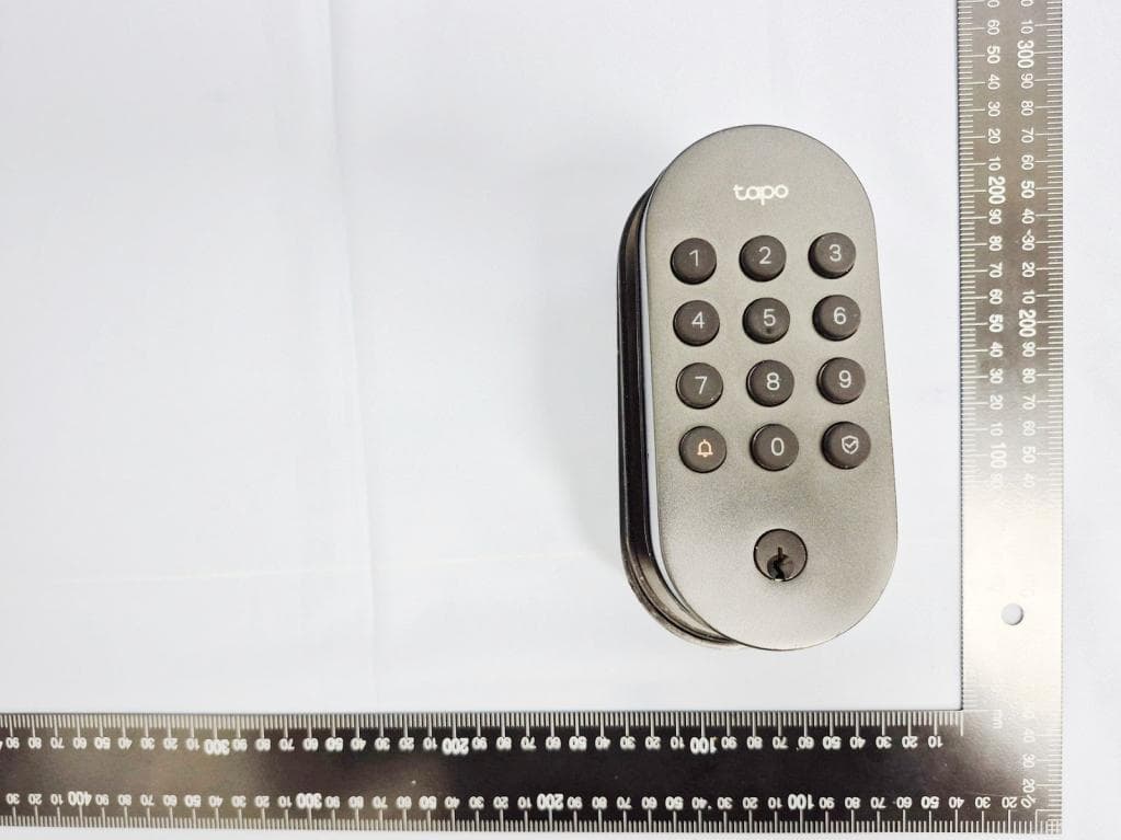
Click to zoom
Application Details
- Equipment Class
- DTS - Digital Transmission System
- Date of Grant
- Sep 18, 2026
- Application Purpose
- Original Equipment
- Equipment Note
- Smart Wi-Fi Door Lock
- Frequency Range
- 2402.00000000 - 2480.00000000
- Company
- TP-Link Systems Inc.
- Country
- United States
Documents & Files
Document Text
Text extracted from the exhibit documents filed with the FCC. Open a document above to read the original.
Users Manual
Quick Start Guide Visit www.tapo.com/support for technical support, user guides, warranty, and more information ? 7100001457 REV1.0.2 © 2025 TP-Link Smart Wi-Fi Door Lock Welcome to Tapo! Installation Guide & Video Scan QR code or visit https://www.tp-link.com/support/faq/4335/ Our expert Technical Support team is ready to assist you. Please don't hesitate to reach out with any questions. Contact Us CALL +1 866 225 8139 (Toll-Free) EMAIL [email protected] CHAT https://livechat.tp-link.com/us For United States https://www.tp-link.com/support/ contact-technical-support/ CALLEMAIL CHAT For Other Countries/Regions 1 5 8 20 22 Parts in the Box Installation Preparation Installation Setup What if the battery is dead while you are outside? Appearance 23 24 How to set the PIN code Contents Parts in the Box 1 BoltStrike PlateDust Box Bolt Screws (ST4*25)×2 Strike Plate Screws (ST4*25)×2 Packaged Together Install the Bolt & Strike Plate TOP Actual Size (M4*7.5)×3 2 Install Exterior Assembly Installation Reference Line Sticker for Exterior Assembly Install Interior Assembly Interior Assembly Exterior Assembly Installation Reference Line Sticker for Interior Assembly Mounting Plate Actual Size (M4*32)×2 3 Install the Interior Mounting Plate Keys ×2Silicone Cover AA/LR6 Batteries ×4 Quick Start Guide Measuring Template guide 4 Others Installation Preparation 5 Compatible with Single Cylinder Deadbolt Lever Handle Lock Not Compatible Integrated Locks Not Compatible Mortise Locks Not Compatible Check Compatibility 1. Check your existing door lock type. 6 2. Measure your door. Place the measuring template on the door, aligning its door edge line with the door edge. 7 Door Thickness 1-3/8’’ to 2-11/64’’ (35-55 mm) Minimum Distance 1-37/64’’ (40 mm) Backset 2-3/8’’ (60 mm) or 2-3/4’’ (70 mm) Align the template with the door edge. Installation 8 Installation Overview 9 1 [Door] TOP Mounting Plate Exterior Assembly Bolt Batteries Interior Assembly Battery Cover 10 Remove your existing lock. 1 Remove your existing door lock and bolt. 11 Install the new bolt. 2 TOP TOP TOP A Ensure the word TOP is facing up. B If the latch hub is not centered in the door hole, twist the bolt to extend it. TOP Center Line Packaged together with the bolt Bolt Screws Twist to extend 1 Install the exterior assembly. 3 12 TOP A Place the exterior assembly sticker on the outside door by aligning its door edge line with the door’s edge. Note: Choose the door edge line based on your backset distance. TOP [OUTSIDE] B Cable goes under the bolt. TOP C Insert the tailpiece and two prongs into the TOP corresponding holes on the bolt and align the exterior assembly with the sticker. Install the mounting plate. 4 13 TOP A Place the interior assembly sticker on the inside door by aligning its door edge line with the door’s edge. Note: Choose the door edge line based on your backset distance. TOP Route the cable through the mounting plate’s rectangular hole and insert the tailpiece into the center round hole. B 14 C Align the mounting plate with the sticker, ensuring the two prongs of the exterior TOP assembly match the two holes next to the center round hole. Secure it with the screws. 15 Install the interior assembly. 5 B Connect the cable tightly. Ensure the color side faces up. Not tightly connected Red marking facing up [INSIDE] A Remove the battery cover. Reset 16 C Align the tailpiece with the thumb-latch slot. You can rotate the thumb latch to adjust the slot. Attach the interior assembly to the mounting plate. D Rotate the thumb latch to ensure the latch retracts normally. Reset Reset 17 E Use the three provided M4*7.5 screws to affix the interior assembly. M4*7.5 Screws Reset 18 Install the batteries. 6 A Insert the batteries into the interior assembly, ensuring the positive and negative terminals are oriented correctly. B Replace the cover by sliding it down. Insert the silicone cover into the bottom hole. Remove the stickers. Reset Reset 19 Install the dust box & strike plate. 7 Insert the dust box and strike plate into the strike hole on the door frame and secure with screws. Ensure the depth of the strike hole is at least 1’’ (25.4 mm). Strike Hole Depth 1’’ (25.4 mm) [Frame] If the bolt operates smoothly without pushing or pulling the door, you can use your original strike plate. If you need to push or pull the door for smooth operation, adjust the strike plate's position on the door frame. Packaged together with the bolt Strike Plate Screws Setup 20 21 2. Tap the button in the app. Select Door Locks and then your model. Follow the app instructions to complete setup. 1. Get the Tapo app from the App Store or Google Play and log in with your TP-Link ID. If you do not have an account, create one first. OR Set Up Your Lock My Home The Tapo app is needed to use this lock. If this lock was professionally installed (or installed by someone other than the homeowner), make sure this step was performed by the homeowner. 22 How to set the PIN code The PIN code should be set in the Tapo app. Tapo will guide you to set your access code. Tapo 23 What if the battery is dead while you are outside? Connect to a power outlet or power bank using a USB cable to provide a temporary power supply. Note that this port is for power only and cannot transfer data. Unlock via the provided key Temporarily power up the lock 5V Appearance 24 25 Appearance 1 2 3 4 Exterior Assembly 1 Keypad Lock/unlock the door by entering your PIN code. 3Ring Button When this button is pressed, you will receive notifications in the app. 55V Type-C Port Connect to a power outlet for a temporary power supply. 4 Lock Cylinder Unlock via the provided keys. 2 When entering the PIN code starting with scrambled digits, press this button to confirm unlocking. When the door is unlocked, press this button to lock it. Indicates the lock/unlock status and device status. Button: Indicator: Lock/Unlock Button & Indicator 5 26 Interior Assembly Thumb Latch Rotate to lock/unlock the d…
Text truncated - open the document above for the full version.
ID Label/Location Info
label location label location S/N:XXXXXXXXXXXXX M AC : X X-X X-X X-X X-X X-X X U S/2.0 FCC ID: 2BH7FDL100V2 IC: 32876-DL100V2 HVIN: Tapo DL100V2
Test Setup Photos
Report No.: 2607TW0120-UT 1 of 7 RF Test Photograph Description: Front View of Conducted Emission Test Setup (BLE) Description: Side View of Conducted Emission Test Setup (BLE) Report No.: 2607TW0120-UT 2 of 7 Description: Front View of Conducted Emission Test Setup (WiFi) Description: Side View of Conducted Emission Test Setup (WiFi) Report No.: 2607TW0120-UT 3 of 7 Description: Radiated Emission Test Setup for below 1GHz (BLE) Description: Radiated Emission Test Setup for above 1GHz (BLE) Report No.: 2607TW0120-UT 4 of 7 Description: Radiated Emission Test Setup for below 1GHz (WiFi) Description: Radiated Emission Test Setup for above 1GHz (WiFi) Report No.: 2607TW0120-UT 5 of 7 Description: Radiated Emission Test Setup for 18GHz~40GHz (BLE) Description: Radiated Emission Test Setup for 9kHz~30MHz (BLE) Report No.: 2607TW0120-UT 6 of 7 Description: Radiated Emission Test Setup for 18GHz~40GHz (WiFi) Description: Radiated Emission Test Setup for 9kHz~30MHz (WiFi) Report No.: 2607TW0120-UT 7 of 7 Description: Conducted Measurement Test Setup (BLE) Description: Conducted Measurement Test Setup (WiFi)
Test Report
MRT Technology (Taiwan) Co., Ltd. Report No.: 2607TW0120-U3 Phone: +886-3-3288388 Report Version: 1.0 Web: www.mrt-cert.com Issue Date: 2026-09-10 Template Version: 2.2 1 of 108 RF MEASUREMENT REPORT FCC ID: 2BH7FDL100V2 Applicant: TP-Link Systems Inc. Product: Smart Wi-Fi Door Lock Model No.: Tapo DL100 Series Model: DLW10 Brand Name: Tapo/TP-Link FCC Classification: Digital Transmission System (DTS) FCC Rule Part(s): Part 15 Subpart C (Section 15.247) Standards: AS/NZS 4268: 2017 AMD 1:2021 Result: Complies Received Date: 2026-07-24 Test Date: 2026-07-28~2026-08-12 Reviewed By: Paddy Chen Approved By: Chenz Ker The test results relate only to the samples tested. This equipment has been shown to be capable of compliance with the applicable technical standards as indicated in the measurement report. Testing was performed in accordance with the applicable measurement procedures. The test results reported herein apply only to the specific item(s) tested. The test report shall not be reproduced except in full without the written approval of MRT Technology (Taiwan) Co., Ltd. Report No.: 2607TW0120-U3 2 of 108 Revision History Report No. Version Description Issue Date Note 2607TW0120-U3 1.0 Original Report 2026-09-10 Valid Report No.: 2607TW0120-U3 3 of 108 CONTENTS Description Page 1. General Information ................................................................................................................................ 5 1.1. Applicant ...................................................................................................................................... 5 1.2. Manufacturer ................................................................................................................................ 5 1.3. Testing Facility ............................................................................................................................. 5 1.4. Product Information ...................................................................................................................... 6 1.5. Radio Specification under Test .................................................................................................... 7 1.6. Working Frequencies ................................................................................................................... 8 1.7. Antenna Details ............................................................................................................................ 9 2. Test Configuration ................................................................................................................................. 10 2.1. Test Mode ................................................................................................................................... 10 2.2. Test System Connection Diagram............................................................................................... 11 2.3. Test Software .............................................................................................................................. 11 2.4. Applied Standards ...................................................................................................................... 12 2.5. Test Environment Condition ....................................................................................................... 12 3. Antenna Requirements ......................................................................................................................... 13 4. Measuring Instrument ........................................................................................................................... 14 5. Decision Rules and Measurement Uncertainty .................................................................................. 15 5.1. Decision Rules ........................................................................................................................... 15 5.2. Measurement Uncertainty .......................................................................................................... 15 6. Test Result .............................................................................................................................................. 16 6.1. Summary .................................................................................................................................... 16 6.2. 6 dB Bandwidth Measurement ................................................................................................... 17 6.2.1. Test Limit .................................................................................................................................... 17 6.2.2. Test Procedure ........................................................................................................................... 17 6.2.3. Test Setting ................................................................................................................................ 17 6.2.4. Test Setup .................................................................................................................................. 17 6.2.5. Test Result ................................................................................................................................. 17 6.3. Output Power Measurement ...................................................................................................... 18 6.3.1. Test Limit .................................................................................................................................... 18 6.3.2. Test Procedure ........................................................................................................................... 18 6.3.3. Test Setting ................................................................................................................................ 18 6.3.4. Test Setup .....................................................................................................................…
Text truncated - open the document above for the full version.
Test Report
MRT Technology (Taiwan) Co., Ltd. Report No.: 2607TW0120-U2 Phone: +886-3-3288388 Report Version: 1.0 Web: www.mrt-cert.com Issue Date: 2026-09-10 Template Version: 2.2 1 of 63 RF MEASUREMENT REPORT FCC ID: 2BH7FDL100V2 Applicant: TP-Link Systems Inc. Product: Smart Wi-Fi Door Lock Model No.: Tapo DL100 Series Model: DLW10 Brand Name: Tapo/TP-Link FCC Classification: Digital Transmission System (DTS) FCC Rule Part(s): Part 15 Subpart C (Section 15.247) Standards: AS/NZS 4268: 2017 AMD 1:2021 Result: Complies Received Date: 2026-07-24 Test Date: 2026-07-29~2026-08-12 Reviewed By: Paddy Chen Approved By: Chenz Ker The test results relate only to the samples tested. This equipment has been shown to be capable of compliance with the applicable technical standards as indicated in the measurement report. Testing was performed in accordance with the applicable measurement procedures. The test results reported herein apply only to the specific item(s) tested. The test report shall not be reproduced except in full without the written approval of MRT Technology (Taiwan) Co., Ltd. Report No.: 2607TW0120-U2 2 of 63 Revision History Report No. Version Description Issue Date Note 2607TW0120-U2 1.0 Original Report 2026-09-10 Valid Report No.: 2607TW0120-U2 3 of 63 CONTENTS Description Page 1. General Information ................................................................................................................................ 5 1.1. Applicant ...................................................................................................................................... 5 1.2. Manufacturer ................................................................................................................................ 5 1.3. Testing Facility ............................................................................................................................. 5 1.4. Product Information ...................................................................................................................... 6 1.5. Radio Specification under Test .................................................................................................... 7 1.6. Working Frequencies ................................................................................................................... 8 2. Test Configuration ................................................................................................................................... 9 2.1. Test Mode ..................................................................................................................................... 9 2.2. Test System Connection Diagram.............................................................................................. 10 2.3. Test Software ............................................................................................................................. 10 2.4. Applied Standards ....................................................................................................................... 11 2.5. Test Environment Condition ........................................................................................................ 11 3. Antenna Requirements ......................................................................................................................... 12 4. Measuring Instrument ........................................................................................................................... 13 5. Decision Rules and Measurement Uncertainty .................................................................................. 14 5.1. Decision Rules ........................................................................................................................... 14 5.2. Measurement Uncertainty .......................................................................................................... 14 6. Test Result .............................................................................................................................................. 15 6.1. Summary .................................................................................................................................... 15 6.2. 6 dB Bandwidth Measurement ................................................................................................... 16 6.2.1. Test Limit .................................................................................................................................... 16 6.2.2. Test Procedure ........................................................................................................................... 16 6.2.3. Test Setting ................................................................................................................................ 16 6.2.4. Test Setup .................................................................................................................................. 16 6.2.5. Test Result ................................................................................................................................. 16 6.3. Output Power Measurement ...................................................................................................... 17 6.3.1. Test Limit .................................................................................................................................... 17 6.3.2. Test Procedure ........................................................................................................................... 17 6.3.3. Test Setting ................................................................................................................................ 17 6.3.4. Test Setup .................................................................................................................................. 17 6.3.5. Test Result .................................................................................................................…
Text truncated - open the document above for the full version.
Test Report
Product Model: DL100(US) 2.0 Manufacturer: TP-Link Systems Inc. Test Date: 2026.5.12 Tested By: Deng yuzhuo TP-Link Systems Inc. 10 Mauchly, Irvine, CA 92618 Index 1. Antenna Distribution ........................................................................................ 3 2. Electrical Characteristics ................................................................................ 3 3. Gain and Radiation Pattern ............................................................................. 4 3.1 Measurement Procedure .......................................................................................... 4 3.2 Test Setup ................................................................................................................ 5 3.3 S Parameter Test Data ............................................................................................. 6 3.4 Antenna Peak Gain .................................................................................................. 7 3.4.1 WiFi Antenna .................................................................................................................... 7 3.4.2 BLE Antenna .................................................................................................................... 7 3.5 Antenna Radiation Pattern ....................................................................................... 7 Page 3 1. Antenna Distribution DL100(US) 2.0 2. Electrical Characteristics Ant1(WiFi) Frequency 2400~2500MHz Impedance 50Ohm Antenna Type Dipole Antenna Gain 4.75dBi@2400~2500MHz Radiation pattern Omni-Directional P/N DL100(US) 2.0_Ant1 Ant2(BLE) Frequency 2400~2500MHz Impedance 50Ohm Antenna Type IFA Antenna Gain 1.38dBi@2400~2500MHz Radiation pattern Omni-Directional P/N DL100(US) 2.0_Ant2 Page 4 3. Gain and Radiation Pattern 3.1 Measurement Procedure This measurement experiment adopted an antenna near-field measurement system, and the diagram of the measurement system was shown in Figure 3-1. The excitation signal was generated by the Keysight E5071C (300kHz-20GHz). Under the control of the central computer, the probe rotated in the θ direction, and the EUT rotated in the φ direction with the turntable. The probe sampling frame received and collected signals in the near-field range of the EUT. The software system which was controlled by the central computer completed the processing, output and display of the test data. Figure 3-1 The test site was a full anechoic chamber with a size of 3.0m×3.1m×2.97m, which was built by GTS Rayzone2800. All six surfaces of the anechoic chamber were pasted with absorbing materials. And the chamber was calibrated by the authoritative third-party lab every year. The antenna anechoic chamber measurement system adopted a 13-probe multi-probe system. The probe antennas were evenly distributed on the spherical surface surrounding the EUT, and theirs operating frequency was 600MHz~8.5GHz. During the measurement, the probe antennas were rotated in the θ direction under the control of the probe holder to sample the near-field data at the θ angle. At the same time, the EUT rotated with the turntable in the φ direction to sample the near field data at the φ angle. The sampling accuracy was 15°. The system diagram was shown in Figure 3-2. From the sampling results, the EUT's near-field test data of θ component, φ component and total component could be obtained. Page 5 Figure 3-2 Before the measurement, calibrated the vector network analyzer, and then connected the input end of each antenna to the output end of the vector network analyzer, and evenly the antennas to be measured. Test Equipment listed below: Equipments Model Manufacturer S/N Cali. Interval Cali. Due Date Chamber Rayzone2800 GTS(General Test System) MY5347043 5 12months 2027/01/15 Vector Network Analyzer E5071C Keysight MY46315238 24months 2027/03/13 GTS MaxSign100 Software V2.1 GTS(General Test System) / / / 3.2 Test Setup The test setup was shown in Figure 3-3, 3-4: Figure 3-3 Page 6 Figure 3-4 3.3 S Parameter Test Data Ant1 Ant2 Page 7 3.4 Antenna Peak Gain 3.4.1 WiFi Antenna Frequency 2.45GHz 2400~2500MHz Ant1 MaxGain(dBi) 4.75 Ant1 Polarization/Φ (°)/θ(°) Theta/60/105 Max Gain(dBi) 4.75 3.4.2 BLE Antenna Frequency 2.45GHz 2400~2500MHz Ant2 MaxGain(dBi) 1.38 Ant2 Polarization/Φ (°)/θ(°) Theta/90/60 Max Gain(dBi) 1.38 3.5 Antenna Radiation Pattern Ant1 Page 8 Ant2
RF Exposure Info
MRT Technology (Taiwan) Co., Ltd. Report No.: 2607TW0120-U4 Phone: +886-3-3288388 Report Version: 1.0 Web: www.mrt-cert.com Issue Date: 2026-09-10 Template Version: 2.1 1 of 11 RF Exposure Evaluation Declaration FCC ID: 2BH7FDL100V2 Applicant: TP-Link Systems Inc. Product: Smart Wi-Fi Door Lock Model No.: Tapo DL100 Series Model: DLW10 FCC Rule Part(s): FCC Part 2.1091 Result: Complies Evaluate Date: 2026-08-18 Reviewed By: Paddy Chen Approved By: Chenz Ker The test results relate only to the samples tested. This equipment has been shown to be capable of compliance with the applicable technical standards as indicated in the measurement report. Testing was performed in accordance with the applicable measurement procedures. The test results reported herein apply only to the specific item(s) tested. The test report shall not be reproduced except in full without the written approval of MRT Technology (Taiwan) Co., Ltd. Report No.: 2607TW0120-U4 2 of 11 Revision History Report No. Version Description Issue Date Note 2607TW0120-U4 1.0 Original Report 2026-09-10 Valid Report No.: 2607TW0120-U4 3 of 11 CONTENTS Description Page 1. General Information ................................................................................................................................4 1.1. Applicant ........................................................................................................................................4 1.2. Manufacturer .................................................................................................................................4 1.3. Testing Facility ...............................................................................................................................4 1.4. Product Information .......................................................................................................................5 1.5. Antenna Details .............................................................................................................................6 1.6. Device Classification .....................................................................................................................6 1.7. Applied Standards .........................................................................................................................6 2. RF Exposure Evaluation .........................................................................................................................7 2.1. Limits .............................................................................................................................................7 2.2. SAR Exemptions ...........................................................................................................................8 2.3. Calculated Result ........................................................................................................................ 11 Report No.: 2607TW0120-U4 4 of 11 1. General Information 1.1. Applicant TP-Link Systems Inc. 10 Mauchly, Irvine, CA 92618 1.2. Manufacturer TP-Link Systems Inc. 10 Mauchly, Irvine, CA 92618 1.3. Testing Facility Test Site 1 - MRT Taiwan Laboratory Laboratory Location No. 38, Fuxing 2nd Rd., Guishan Dist., Taoyuan City 333, Taiwan (R.O.C.) Laboratory Accreditations TAF: 3261 FCC: 291082, TW3261 ISED: TW3261 Test Site 2 - MRT Taiwan Laboratory Laboratory Location No. 64, Wenming Rd., Guishan Dist., Taoyuan City 333, Taiwan (R.O.C.) Laboratory Accreditations TAF: 3261 FCC: 291082, TW3261 ISED: TW3261 Report No.: 2607TW0120-U4 5 of 11 1.4. Product Information Product Name Smart Wi-Fi Door Lock Model No. Tapo DL100 Series Model DLW10 Specification WLAN: 802.11b/g/n WPAN: BLE only Antenna Information Refer to section 1.5 Operating Environment Indoor Use Power type 1. By AC/DC adapter 2. By Battery Note: The information of the EUT (Equipment Under Test) was provided by the manufacturer. The accuracy, completeness, and validity of the information are solely the responsibility of the manufacturer. Note: 1. Model Difference: The difference of models only for marketing different, the other hardware was the same. (declared by the manufacturer) 2. The test was performed base on Tapo DL100. Report No.: 2607TW0120-U4 6 of 11 1.5. Antenna Details Antenna Type Frequency Band (MHz) Antenna Gain (dBi) Wi-Fi Antenna Dipole 2412 ~ 2462 4.75 BLE Antenna IFA 2402 ~ 2480 1.38 Note: The antenna gain is from antenna data sheet provided by the manufacturer. 1.6. Device Classification According to the user manual, this device is classified as a Mobile Device. So, the RF exposure evaluation requirements of § 2.1091 for Mobile device exposure conditions subject to SAR limits. 1.7. Applied Standards According to the specifications of the manufacturer, the EUT must comply with the requirements of the following standards: ⚫ FCC Part 2.1091 ⚫ KDB 447498 D04 Interim General RF Exposure Guidance v01 Report No.: 2607TW0120-U4 7 of 11 2. RF Exposure Evaluation 2.1. Limits According to FCC §1.1310: (a) Specific absorption rate (SAR) shall be used to evaluate the environmental impact of human exposure to radiofrequency (RF) radiation as specified in § 1.1307(b) of this part within the frequency range of 100 kHz to 6 GHz (inclusive). (b) The SAR limits for occupational/controlled exposure are 0.4 W/kg, as averaged over the whole body, and a peak spatial-average SAR of 8 W/kg, averaged over any 1 gram of tissue (defined as a tissue volume in the shape of a cube). Exceptions are the parts of the human body treated as extremities, such as hands, wrists, feet, ankles, and pinnae, where the peak spatial-average SAR limit for occupational/controlled exposure is 20 W/kg, averaged over any 10 grams of tissue (defined as a tissue volume in the shape of a cube). Exposure may be averaged over a time period not to exceed 6 minutes to determine compliance with occupational/controlled SAR limits. (c) The SAR limits for general population/uncontrolled exposure are 0.08 W/kg…
Text truncated - open the document above for the full version.
Internal Photos
Report No.: 2607TW0120-UI 1 of 11 Internal Photograph (1) EUT Photo (2) EUT Photo Report No.: 2607TW0120-UI 2 of 11 (3) EUT Photo (4) EUT Photo Report No.: 2607TW0120-UI 3 of 11 (5) EUT Photo (6) EUT Photo Report No.: 2607TW0120-UI 4 of 11 (7) EUT Photo (8) EUT Photo Report No.: 2607TW0120-UI 5 of 11 (9) EUT Photo (10) EUT Photo Report No…
Text truncated - open the document above for the full version.
Contact Information
Applicant
Sarah Wang
[email protected]Fax: 6263330234
Technical Contact
Test Firm
MRT Technology (Taiwan) Co.,LtdChenz Ker
[email protected]Fax: +886-3-328-8918
Technical Specifications
| # | Rule Parts | Frequency Range | Power Output |
|---|---|---|---|
| 1 | 15C | 2.40 GHz - 2.48 GHz | 5.60 mW |
| 2 | 15C | 2.41 GHz - 2.46 GHz | 80.90 mW |