2BH7FEAP725ODBE5000 Indoor/Outdoor Wi-Fi 7 Access Point
TP-Link Systems Inc.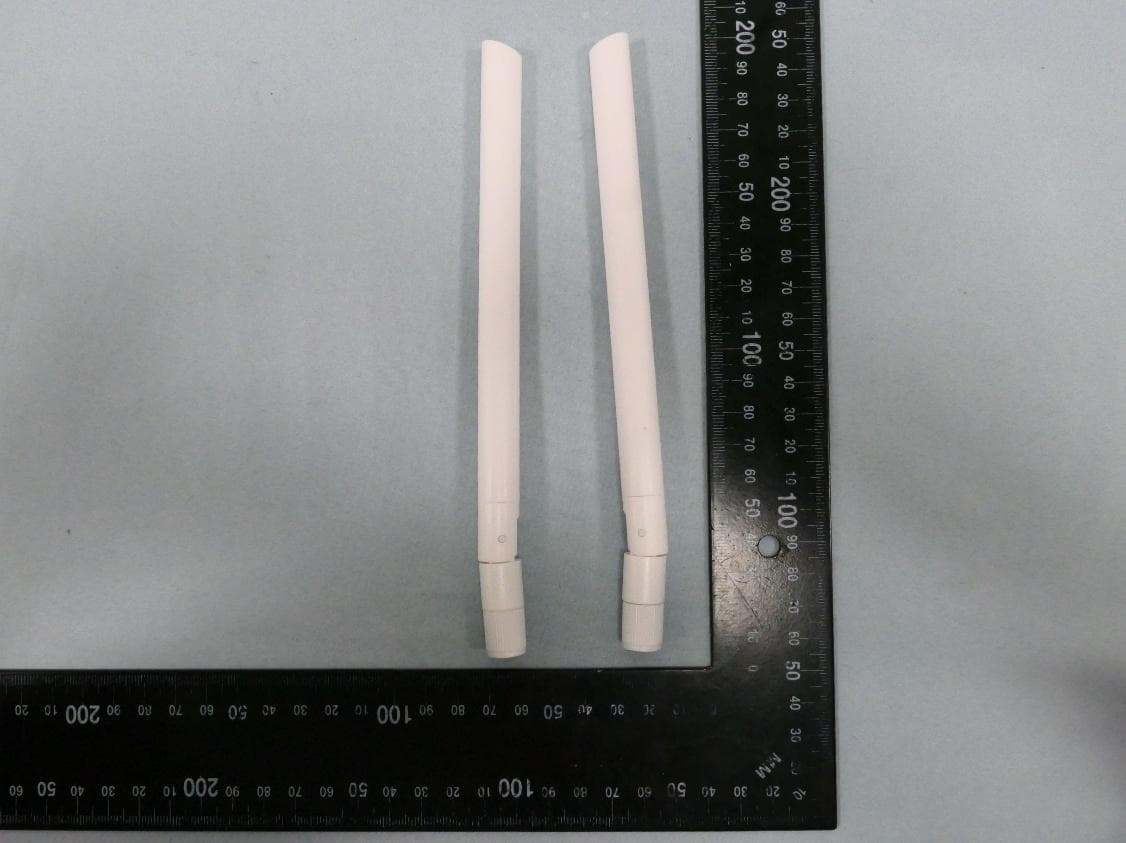
Click to zoom
Application Details
- Equipment Class
- DTS - Digital Transmission System
- Date of Grant
- Nov 23, 2025
- Application Purpose
- Original Equipment
- Equipment Note
- BE5000 Indoor/Outdoor Wi-Fi 7 Access Point
- Frequency Range
- 2402.00000000 - 2480.00000000
- Company
- TP-Link Systems Inc.
- Country
- United States
Documents & Files
Document Text
Text extracted from the exhibit documents filed with the FCC. Open a document above to read the original.
Users Manual
Regulatory Compliance Indoor/Outdoor EAP © 2025 TP-Link 1910013244 REV2.3.0 For Class B EAP with adapter: FCC Compliance Information Statement Product Name: Omada Indoor/Outdoor Access Point/Wireless Bridge Model Number: EAP100-Bridge / EAP211-Bridge V3 / EAP215-Bridge V3 / Beam Bridge 5 UR / EAP603-Outdoor / EAP610-Outdoor / EAP725-Outdoor Component NameModel I.T.E. Power Supply T120100-2B1 (for EAP100-Bridge) POE2412G (for EAP211-Bridge V3 / EAP215-Bridge V3 / Beam Bridge 5 UR) POE4824G (for EAP603-Outdoor) TL-POE4824G (for EAP610-Outdoor) Responsible party: TP-Link Systems Inc. Address: 10 Mauchly, Irvine, CA 92618 Website: https://www.tp-link.com/us/ Tel: +1 626 333 0234 Fax: +1 909 527 6804 E-mail: [email protected] This equipment has been tested and found to comply with the limits for a Class B digital device, pursuant to part 15 of the FCC Rules. These limits are designed to provide reasonable protection against harmful interference in a residential installation. This equipment generates, uses and can radiate radio frequency energy and, if not installed and used in accordance with the instructions, may cause harmful interference to radio communications. However, there is no guarantee that interference will not occur in a particular installation. If this equipment does cause harmful interference to radio or television reception, which can be determined by turning the equipment off and on, the user is encouraged to try to correct the interference by one or more of the following measures: •Reorient or relocate the receiving antenna. •Increase the separation between the equipment and receiver. •Connect the equipment into an outlet on a circuit different from that to which the receiver is connected. •Consult the dealer or an experienced radio/ TV technician for help. This device complies with part 15 of the FCC Rules. Operation is subject to the following two conditions: 1) This device may not cause harmful interference. 2) This device must accept any interference received, including interference that may cause undesired operation. Any changes or modifications not expressly approved by the party responsible for compliance could void the user’s authority to operate the equipment. Note: The manufacturer is not responsible for any radio or TV interference caused by unauthorized modifications to this equipment. Such modifications could void the user’s authority to operate the equipment. FCC RF Radiation Exposure Statement: This equipment complies with FCC RF radiation exposure limits set forth for an uncontrolled environment. This device and its antenna must not be co-located or operating in conjunction with any other antenna or transmitter. “To comply with FCC RF exposure compliance requirements, this grant is applicable to only Mobile Configurations. The antennas used for this transmitter must be installed to provide a separation distance of at least 25cm (for EAP610-Outdoor / EAP100-Bridge) / 20cm (for other models) from all persons and must not be colocated or operating in conjunction with any other antenna or transmitter.” Product Name: I.T.E. Power Supply Model Number: T120100-2B1 / POE2412G / POE4824G / TL-POE4824G Responsible party: TP-Link Systems Inc. Address: 10 Mauchly, Irvine, CA 92618 Website: https://www.tp-link.com/us/ Tel: +1 626 333 0234 Fax: +1 909 527 6804 E-mail: [email protected] This equipment has been tested and found to comply with the limits for a Class B digital device, pursuant to part 15 of the FCC Rules. These limits are designed to provide reasonable protection against harmful interference in a residential installation. This equipment generates, uses and can radiate radio frequency energy and, if not installed and used in accordance with the instructions, may cause harmful interference to radio communications. However, there is no guarantee that interference will not occur in a particular installation. If this equipment does cause harmful interference to radio or television reception, which can be determined by turning the equipment off and on, the user is encouraged to try to correct the interference by one or more of the following measures: •Reorient or relocate the receiving antenna. • Increase the separation between the equipment and receiver. •Connect the equipment into an outlet on a circuit different from that to which the receiver is connected. •Consult the dealer or an experienced radio/ TV technician for help. This device complies with part 15 of the FCC Rules. Operation is subject to the following two conditions: 1) This device may not cause harmful interference. 2) This device must accept any interference received, including interference that may cause undesired operation. Any changes or modifications not expressly approved by the party responsible for compliance could void the user’s authority to operate the equipment. We, TP-Link Systems Inc., has determined that the equipment shown as above has been shown to comply with the applicable technical standards, FCC part 15. There is no unauthorized change is made in the equipment and the equipment is properly maintained and operated. Issue Date: 2025/08/11 CE Mark Warning OPERATING FREQUENCY (the maximum transmitted power) For EAP100-Bridge: 2412MHz—2472MHz (20dBm) For EAP211-Bridge V3 / EAP215-Bridge V3 / Beam Bridge 5 UR: 5150MHz—5250MHz (23dBm) 5250MHz—5350MHz (23dBm) 5470MHz—5725MHz (30dBm) For EAP610-Outdoor: 2412MHz—2472MHz (20dBm) 5150MHz—5250MHz (23dBm) 5250MHz—5350MHz (23dBm) 5470MHz—5725MHz (30dBm) For EAP603-Outdoor / EAP725-Outdoor: 2402 MHz-2480 MHz (10dBm) 2412MHz—2472MHz (20dBm) 5150MHz—5250MHz (23dBm) 5250MHz—5350MHz (23dBm) 5470MHz—5725MHz (30dBm) EU Declaration of Conformity For EAP725-Outdoor: TP-Link hereby declares that the Access Point is in compliance with the essential requirements and other relevant provisions of directives 2014/53/EU, 2011/65/EU and (EU)2015/863. For other models: TP-Link hereby declares that the Access Point is in compliance with the essential requi…
Text truncated - open the document above for the full version.
Users Manual
Quick Installation Guide Installation Package Contents Option 1: Pole Mounting 2× 1 2 3 Option 2: Wall Mounting 1 2 3 4 5 2× 2× 1× 2× 1× Mounting Kit Quick Installation Guide 2× 2×2× Φ 7.6 mm (19/64 in) Indoor/Outdoor Access Point Note: EAP725-Outdoor is used as an example throughout the guide. Images may differ from your actual product. Note: Install the EAP in the direction as shown below. ©2025 TP-Link 7100001336 REV1.0.0 Scan for EAP Start Guide 4 Or Or Or 3 mm≤Φ≤6 mm 3 mm≤Φ≤6 mm 2×2×2× OROR 1× 2× More Configurations For more configurations, refer to the User Guides of the Omada Controller and Omada Access Points at: https://support.omadanetworks.com/document/ Omada App With the TP-Link Omada app, you can access and manage your Omada devices at a local site or remotely with a tap of your phone. Scan for Omada App Switch Gateway/Router On-Premises Controller Omada Central (Cloud-Based) Or Controller EAPEAPEAP Configure and manage EAPs (and other Omada devices) centrally with an Omada Controller. Option 2: Controller Mode Scan for Controller Start Guide Configuration Switch Gateway/Router EAPEAPEAP Configure and manage each EAP on its standalone page. Option 1: Standalone Mode Scan for Standalone Start Guide Option 3: Junction Box Mounting 1 1 2 2 3 4 5 Choose the accessory screws that fit your junction box. These are compatible wall junctions: For simplicity, an Standard US wall junction box is used as an example. 1× 2× Safety Information • Keep the device away from fire or hot environments. DO NOT immerse in water or any other liquid. • Do not attempt to disassemble, repair, or modify the device. If you need service, please contact us. • Do not use the device where wireless devices are not allowed. • This EAP can be powered only by the passive PoE adapter or equipment that complies with Power Source Class 2 (PS2) or Limited Power Source (LPS) defined in the standard of IEC 62368-1. TP-Link hereby declares that the Access Point is in compliance with the essential requirements and other relevant provisions of directives 2014/53/EU, 2011/65/EU, and (EU)2015/863. The original EU Declaration of Conformity may be found at https://www.tp-link.com/en/support/ce/. TP-Link hereby declares that the Access Point is in compliance with the essential requirements and other relevant provisions of the Radio Equipment Regulations 2017. The original UK Declaration of Conformity may be found at https://www.tp-link.com/support/ukca/ Attention: In EU member states, EFTA countries and Northern Ireland, the operation in the frequency range 5150MHz-5350MHz is only permitted indoors. Attention: In Great Britain, the operation in the frequency range 5150MHz - 5350MHz is only permitted indoors. For the EAP Controller, go to the Devices page and select the desired EAP to specify the channel. For the web browser, go to Wireless > Wireless Settings to specify the channel. AT EE IS NO PL PT RO SESISK UK(NI) IT LI LT LU LV MTNL EL ESFIFR HR HUIE BE BG CHCY CZDEDK UK For details on the warranty period, policy, and procedures, visit https://support.omadanetworks.com/warranty-services/. Warranty Support For technical support, user guides, and other information, please visit https://support.omadanetworks.com/, or simply scan the QR code. More Resources Main Sitehttps://www.omadanetworks.com/ https://support.omadanetworks.com/video/ https://support.omadanetworks.com/document/ https://support.omadanetworks.com/product/ https://support.omadanetworks.com/contact-support/ Video Center Product Support Documents Technical Support 1. Grounding Connection External Antenna Installation (Recommended) Antenna Orientation Note: For lightning and ESD protection, connect the EAP’s grounding terminal to grounding facilities using a proper grounding wire, which should meet local installation requirements. 2. Power On PoE Switch 90° 45° 5 GHz 2.4 GHz 2.4 GHz 2.4 / 5 GHz 3 mm≤Φ≤6 mm 2×2×2× OROR
Test Report
Copyright © 2024 TP-Link Systems Inc. All rights reserved FCC Composite Gain Test Report TP-Link Systems Inc. 10 Mauchly, Irvine, CA 926187 Copyright © 2024 TP-Link Systems Inc. All rights reserved Copyright © 2024 By TP-Link Systems Inc. All rights reserved. The drawings, specifications and the data contained in this document are exclusively the property of TP-Link Systems Inc. The information is intended for internal use only and is subject to change without any notice. With no written permission from TP-Link Systems Inc. this document, in parts or as a whole, shall not be reproduced, copied, or used in any form or by any means to make any derivatives such as translation, transformation, or adaptation, for any purpose whatever. is a registered trademark of TP-Link Systems Inc. Other brands and product names mentioned herein are trademarks or registered trademarks of their respective holders. Warning This document is intended for internal use only. A Non-Disclosure Agreement (NDA) approved by Chief Technology Officer (CTO) is required to release this document under any circumstances. Basic Information EUT Description: BE5000 Indoor/Outdoor Dual-Band Wi-Fi 7 Access Point Brand Name: tp-link Model Name: EAP725 Outdoor Tested By: Chen Xuemeng Date: 2025/06/12 Copyright © 2024 TP-Link Systems Inc. All rights reserved CONTENTS 1 Operation Mode and Antenna Information ........................................................................................ 5 1.1 EUT Operation Mode ...................................................................................................................... 5 1.2 Antenna Information ....................................................................................................................... 5 1.3 Test Frequency ................................................................................................................................ 5 2 Test System ............................................................................................................................................. 6 2.1 Test Equipment ................................................................................................................................ 6 2.2 Test Software ................................................................................................................................... 6 3 Test Summary ........................................................................................................................................ 7 3.1 Measurement Environment ............................................................................................................. 7 3.2 Measurement Quantity .................................................................................................................... 9 3.3 Test Method ..................................................................................................................................... 9 3.4 Directional Gain Calculations ....................................................................................................... 10 3.5 Directional Gain (Nss=N ant ) Calculations ..................................................................................... 11 3.6 Test Procedure ............................................................................................................................... 11 4 Measured Value and Maximum Gain Positions................................................................................ 13 4.1 Antenna Number ........................................................................................................................... 13 4.2 2G .................................................................................................................................................. 13 4.2.1 DG_1SS Max Value Position ................................................................................................ 13 4.2.2 DG_1SS Max Value Position Calculation ............................................................................. 13 4.2.3 DG_NSSmax Max Value Position ......................................................................................... 13 4.2.4 DG_NSSmax Max Value Position Calculation ..................................................................... 14 4.3 5G .................................................................................................................................................. 14 4.3.1 DG_1SS Max Value Position ................................................................................................ 14 4.3.2 DG_1SS Max Value Position Calculation ............................................................................. 14 4.3.3 DG_NSSmax Max Value Position ......................................................................................... 15 4.3.4 DG_NSSmax Max Value Position Calculation ..................................................................... 15 5 Test and Calculate Result ................................................................................................................... 15 5.1 Peak Antenna Gain(Single) ...................................................................................................... 15 5.2 DG_1SS Calculate Result ............................................................................................................. 15 5.3 DG_NSSmax Calculate Result ...................................................................................................... 16 6 Test Pattern .......................................................................................................................................... 17 6.1 Antenna Pattern ............................................................................................................................. 17 Copyright © 2024 TP-Link Systems Inc. All rights reserved 7 Test Pattern .....................................................................…
Text truncated - open the document above for the full version.
Test Setup Photos
Report No.: 2507TW0125-UT 1 of 8 BLE Test Photograph Description: Front View of Conducted Emission Test Setup Description: Back View of Conducted Emission Test Setup Report No.: 2507TW0125-UT 2 of 8 Description: Radiated Emission Test Setup for below 1GHz Description: Radiated Emission Test Setup for above 1GHz Report No.: 2507TW0125-UT 3 of 8 Description: Radiated Emission Test Setup for 18GHz~40GHz Description: Radiated Emission Test Setup for 9kHz~30MHz Report No.: 2507TW0125-UT 4 of 8 Description: Conducted Test Setup Report No.: 2507TW0125-UT 5 of 8 Wi-Fi Test Photograph Description: Front View of Conducted Emission Test Setup Description: Back View of Conducted Emission Test Setup Report No.: 2507TW0125-UT 6 of 8 Description: Radiated Emission Test Setup for below 1GHz Description: Radiated Emission Test Setup for above 1GHz Report No.: 2507TW0125-UT 7 of 8 Description: Radiated Emission Test Setup for 18GHz~40GHz Description: Radiated Emission Test Setup for 9kHz~30MHz Report No.: 2507TW0125-UT 8 of 8 Description: Conducted Test Setup Description: DFS Test Setup
Test Setup Photos
Report No.: 2507TW0125-CT 1 of 8 BLE Test Photograph Description: Front View of Conducted Emission Test Setup Description: Back View of Conducted Emission Test Setup Report No.: 2507TW0125-CT 2 of 8 Description: Radiated Emission Test Setup for below 1GHz Description: Radiated Emission Test Setup for above 1GHz Report No.: 2507TW0125-CT 3 of 8 Description: Radiated Emission Test Setup for 18GHz~40GHz Description: Radiated Emission Test Setup for 9kHz~30MHz Report No.: 2507TW0125-CT 4 of 8 Description: Conducted Test Setup Report No.: 2507TW0125-CT 5 of 8 Wi-Fi Test Photograph Description: Front View of Conducted Emission Test Setup Description: Back View of Conducted Emission Test Setup Report No.: 2507TW0125-CT 6 of 8 Description: Radiated Emission Test Setup for below 1GHz Description: Radiated Emission Test Setup for above 1GHz Report No.: 2507TW0125-CT 7 of 8 Description: Radiated Emission Test Setup for 18GHz~40GHz Description: Radiated Emission Test Setup for 9kHz~30MHz Report No.: 2507TW0125-CT 8 of 8 Description: Conducted Test Setup Description: DFS Test Setup
Test Report
Report No.: 2507TW0125-U3 Page Number: 88 of 453 802.11 n40 CH03 (2422MHz) 802.11 n40 CH03 (2422MHz) 802.11 n40 CH06 (2437MHz) 802.11 n40 CH06 (2437MHz) 802.11 n40 CH09 (2452MHz) 802.11 n40 CH09 (2452MHz) Report No.: 2507TW0125-U3 Page Number: 89 of 453 802.11 ax20 CH01 (2412MHz) 802.11 ax20 CH01 (2412MHz) 802.11 ax20 CH06 (2437MHz) 802.11 ax20 CH06 (2437MHz) 802.11 ax20 CH11 (2462MHz) 802.11 ax20 CH11 (2462MHz) Report No.: 2507TW0125-U3 Page Number: 90 of 453 802.11 ax40 CH03 (2422MHz) 802.11 ax40 CH03 (2422MHz) 802.11 ax40 CH06 (2437MHz) 802.11 ax40 CH06 (2437MHz) 802.11 ax40 CH09 (2452MHz) 802.11 ax40 CH09 (2452MHz) Report No.: 2507TW0125-U3 Page Number: 91 of 453 802.11be20 CH01 (2412MHz) 802.11be20 CH01 (2412MHz) 802.11be20 CH06 (2437MHz) 802.11be20 CH06 (2437MHz) 802.11be20 CH11 (2462MHz) 802.11be20 CH11 (2462MHz) Report No.: 2507TW0125-U3 Page Number: 92 of 453 802.11be40 CH03 (2422MHz) 802.11be40 CH03 (2422MHz) 802.11be40 CH06 (2437MHz) 802.11be40 CH06 (2437MHz) 802.11be40 CH09 (2452MHz) 802.11be40 CH09 (2452MHz) Report No.: 2507TW0125-U3 Page Number: 93 of 453 7.6. Radiated Spurious Emission Measurement 7.6.1.Test Limit All out of band emissions appearing in a restricted band as specified in Section 15.205 of the Title 47CFR must not exceed the limits shown in Table per Section 15.209. FCC Part 15 Subpart C Paragraph 15.209 Frequency [MHz] Field Strength [Uv/m] Measured Distance [Meters] 0.009 - 0.490 2400/F (kHz) 300 0.490 - 1.705 24000/F (kHz) 30 1.705 - 30 30 30 30 - 88 100 3 88 - 216 150 3 216 - 960 200 3 Above 960 500 3 7.6.2.Test Procedure Used ANSI C63.10 - 2020 Section 11.11 & 11.12 ANSI C63.10 - 2020 Section 6.3 (General Requirements) ANSI C63.10 - 2020 Section 6.4 (Standard test method below 30MHz) ANSI C63.10 - 2020 Section 6.5 (Standard test method above 30MHz to 1GHz) ANSI C63.10 - 2020 Section 6.6 (Standard test method above 1GHz) 7.6.3.Test Setting Table 1 - RBW as a function of frequency Frequency RBW 9 ~ 150 kHz 200 ~ 300 Hz 0.15 ~ 30 MHz 9 ~ 10 kHz 30 ~ 1000 MHz 100 ~ 120 kHz > 1000MHz 1MHz Report No.: 2507TW0125-U3 Page Number: 94 of 453 Quasi-Peak Measurements below 1GHz 1. Analyzer center frequency was set to the frequency of the radiated spurious emission of interest 2. Span was set greater than 1MHz 3. RBW = as specified in Table 1 4. Detector = CISPR quasi-peak 5. Sweep time = auto couple 6. Trace was allowed to stabilize Peak Measurements above 1GHz 1. Analyzer center frequency was set to the frequency of the radiated spurious emission of interest 2. RBW = 1MHz 3. VBW = 3MHz 4. Detector = peak 5. Sweep time = auto couple 6. Trace mode = max hold 7. Trace was allowed to stabilize Average Measurements above 1GHz (Method VB) 1. Analyzer center frequency was set to the frequency of the radiated spurious emission of interest 2. RBW = 1MHz 3. VBW; If the EUT is configured to transmit with duty cycle ≥ 98%, set VBW = 10 Hz. If the EUT duty cycle is < 98%, set VBW ≥ 1/T. T is the minimum transmission duration. 4. Detector = Peak 5. Sweep time = auto 6. Trace mode = max hold 7. Trace was allowed to stabilize Report No.: 2507TW0125-U3 Page Number: 95 of 453 7.6.4.Test Setup Below 1GHz Test Setup: Above 1GHz Test Setup: Report No.: 2507TW0125-U3 Page Number: 96 of 453 7.6.5.Test Result EUT BE5000 Indoor/Outdoor Wi-Fi 7 Access Point Date of Test 2025-09-23 Factor VULB 9162 Temp. / Humidity 21C /63% Polarity Horizontal Site / Test Engineer AC2 / Marcus Test Mode 802.11n-20MHz_TX_CH 6_Ant 1+2_External Ant Test Voltage By PoE No Frequency (MHz) Reading (dBuV) C.F (dB/m) Measurement (dBuV/m) Margin (dB) Limit (dBuV/m) Height (cm) Angle (deg) Remark (QP/PK/AV) 1 112.131 8.48 18.28 26.75 -16.75 43.50 200 49 QP 2 * 159.225 23.66 15.84 39.50 -4.00 43.50 200 312 QP 3 183.201 17.07 17.08 34.16 -9.34 43.50 200 95 QP 4 211.527 14.43 18.21 32.64 -10.86 43.50 200 319 QP 5 315.481 9.41 21.55 30.96 -15.04 46.00 200 339 QP 6 374.623 7.26 23.14 30.40 -15.60 46.00 200 303 QP Note: 1. " *", means this data is the worst emission level. 2. C.F (Correction Factor) = Antenna Factor (dB/m) + Cable Loss (dB). 3. Measurement (dBuV/m) = Reading(dBuV) + C.F (Correction Factor). 4. The emission levels of other frequencies are very lower than the limit and not show in test report. 5. The amplitude of radiated emissions (frequency range from 9kHz to 30MHz) is that proximity to ambient noise, which also are attenuated more than 20dB below the permissible value. Therefore, the data is not presented in the report. Report No.: 2507TW0125-U3 Page Number: 97 of 453 EUT BE5000 Indoor/Outdoor Wi-Fi 7 Access Point Date of Test 2025-09-23 Factor VULB 9162 Temp. / Humidity 21C /63% Polarity Vertical Site / Test Engineer AC2 / Marcus Test Mode 802.11n-20MHz_TX_CH 6_Ant 1+2_External Ant Test Voltage By PoE No Frequency (MHz) Reading (dBuV) C.F (dB/m) Measurement (dBuV/m) Margin (dB) Limit (dBuV/m) Height (cm) Angle (deg) Remark (QP/PK/AV) 1 * 31.843 21.96 17.64 39.60 -0.40 40.00 100 344 QP 2 43.506 15.21 20.67 35.88 -4.12 40.00 100 62 QP 3 58.613 18.53 19.93 38.47 -1.53 40.00 100 74 QP 4 66.967 16.22 17.20 33.42 -6.58 40.00 100 2 QP 5 155.364 23.46 15.68 39.14 -4.36 43.50 100 7 QP 6 162.611 24.69 15.96 40.65 -2.85 43.50 100 3 QP Note: 1. " *", means this data is the worst emission level. 2. C.F (Correction Factor) = Antenna Factor (dB/m) + Cable Loss (dB). 3. Measurement (dBuV/m) = Reading(dBuV) + C.F (Correction Factor). 4. The emission levels of other frequencies are very lower than the limit and not show in test report. 5. The amplitude of radiated emissions (frequency range from 9kHz to 30MHz) is that proximity to ambient noise, which also are attenuated more than 20dB below the permissible value. Therefore, the data is not presented in the report. Report No.: 2507TW0125-U3 Page Number: 98 of 453 EUT BE5000 Indoor/Outdoor Wi-Fi 7 Access Point Date of Test 2025-09-23 Factor VULB 9162 Temp. / Humidity 21C /63% Polarity Horizontal Site / Test Engineer AC2 / Marcus Test Mode 802.11n-20MHz_TX_CH 6_Ant 1+2_In…
Text truncated - open the document above for the full version.
Test Report
Report No.: 2507TW0125-U3 Page Number: 78 of 453 802.11 g CH01 (2412MHz) 802.11 g CH01 (2412MHz) 802.11 g CH06 (2437MHz) 802.11 g CH06 (2437MHz) 802.11 g CH11 (2462MHz) 802.11 g CH11 (2462MHz) Report No.: 2507TW0125-U3 Page Number: 79 of 453 802.11 n20 CH01 (2412MHz) 802.11 n20 CH01 (2412MHz) 802.11 n20 CH06 (2437MHz) 802.11 n20 CH06 (2437MHz) 802.11 n20 CH11 (2462MHz) 802.11 n20 CH11 (2462MHz) Report No.: 2507TW0125-U3 Page Number: 80 of 453 802.11 n40 CH03 (2422MHz) 802.11 n40 CH03 (2422MHz) 802.11 n40 CH06 (2437MHz) 802.11 n40 CH06 (2437MHz) 802.11 n40 CH09 (2452MHz) 802.11 n40 CH09 (2452MHz) Report No.: 2507TW0125-U3 Page Number: 81 of 453 802.11 ax20 CH01 (2412MHz) 802.11 ax20 CH01 (2412MHz) 802.11 ax20 CH06 (2437MHz) 802.11 ax20 CH06 (2437MHz) 802.11 ax20 CH11 (2462MHz) 802.11 ax20 CH11 (2462MHz) Report No.: 2507TW0125-U3 Page Number: 82 of 453 802.11 ax40 CH03 (2422MHz) 802.11 ax40 CH03 (2422MHz) 802.11 ax40 CH06 (2437MHz) 802.11 ax40 CH06 (2437MHz) 802.11 ax40 CH09 (2452MHz) 802.11 ax40 CH09 (2452MHz) Report No.: 2507TW0125-U3 Page Number: 83 of 453 802.11be20 CH01 (2412MHz) 802.11be20 CH01 (2412MHz) 802.11be20 CH06 (2437MHz) 802.11be20 CH06 (2437MHz) 802.11be20 CH11 (2462MHz) 802.11be20 CH11 (2462MHz) Report No.: 2507TW0125-U3 Page Number: 84 of 453 802.11be40 CH03 (2422MHz) 802.11be40 CH03 (2422MHz) 802.11be40 CH06 (2437MHz) 802.11be40 CH06 (2437MHz) 802.11be40 CH09 (2452MHz) 802.11be40 CH09 (2452MHz) Report No.: 2507TW0125-U3 Page Number: 85 of 453 Ant 2 802.11 b CH01 (2412MHz) 802.11 b CH01 (2412MHz) 802.11 b CH06 (2437MHz) 802.11 b CH06 (2437MHz) 802.11 b CH11 (2462MHz) 802.11 b CH11 (2462MHz) Report No.: 2507TW0125-U3 Page Number: 86 of 453 802.11 g CH01 (2412MHz) 802.11 g CH01 (2412MHz) 802.11 g CH06 (2437MHz) 802.11 g CH06 (2437MHz) 802.11 g CH11 (2462MHz) 802.11 g CH11 (2462MHz) Report No.: 2507TW0125-U3 Page Number: 87 of 453 802.11 n20 CH01 (2412MHz) 802.11 n20 CH01 (2412MHz) 802.11 n20 CH06 (2437MHz) 802.11 n20 CH06 (2437MHz) 802.11 n20 CH11 (2462MHz) 802.11 n20 CH11 (2462MHz)
Test Report
Report No.: 2507TW0125-U3 Page Number: 67 of 453 802.11be40 CH03 (2422MHz) 802.11be40 CH03 (2422MHz) 802.11be40 CH06 (2437MHz) 802.11be40 CH06 (2437MHz) 802.11be40 CH09 (2452MHz) 802.11be40 CH09 (2452MHz) Report No.: 2507TW0125-U3 Page Number: 68 of 453 Ant 2 802.11 b CH01 (2412MHz) 802.11 b CH01 (2412MHz) 802.11 b CH06 (2437MHz) 802.11 b CH06 (2437MHz) 802.11 b CH11 (2462MHz) 802.11 b CH11 (2462MHz) Report No.: 2507TW0125-U3 Page Number: 69 of 453 802.11 g CH01 (2412MHz) 802.11 g CH01 (2412MHz) 802.11 g CH06 (2437MHz) 802.11 g CH06 (2437MHz) 802.11 g CH11 (2462MHz) 802.11 g CH11 (2462MHz) Report No.: 2507TW0125-U3 Page Number: 70 of 453 802.11 n20 CH01 (2412MHz) 802.11 n20 CH01 (2412MHz) 802.11 n20 CH06 (2437MHz) 802.11 n20 CH06 (2437MHz) 802.11 n20 CH11 (2462MHz) 802.11 n20 CH11 (2462MHz) Report No.: 2507TW0125-U3 Page Number: 71 of 453 802.11 n40 CH03 (2422MHz) 802.11 n40 CH03 (2422MHz) 802.11 n40 CH06 (2437MHz) 802.11 n40 CH06 (2437MHz) 802.11 n40 CH09 (2452MHz) 802.11 n40 CH09 (2452MHz) Report No.: 2507TW0125-U3 Page Number: 72 of 453 802.11 ax20 CH01 (2412MHz) 802.11 ax20 CH01 (2412MHz) 802.11 ax20 CH06 (2437MHz) 802.11 ax20 CH06 (2437MHz) 802.11 ax20 CH11 (2462MHz) 802.11 ax20 CH11 (2462MHz) Report No.: 2507TW0125-U3 Page Number: 73 of 453 802.11 ax40 CH03 (2422MHz) 802.11 ax40 CH03 (2422MHz) 802.11 ax40 CH06 (2437MHz) 802.11 ax40 CH06 (2437MHz) 802.11 ax40 CH09 (2452MHz) 802.11 ax40 CH09 (2452MHz) Report No.: 2507TW0125-U3 Page Number: 74 of 453 802.11be20 CH01 (2412MHz) 802.11be20 CH01 (2412MHz) 802.11be20 CH06 (2437MHz) 802.11be20 CH06 (2437MHz) 802.11be20 CH11 (2462MHz) 802.11be20 CH11 (2462MHz) Report No.: 2507TW0125-U3 Page Number: 75 of 453 802.11be40 CH03 (2422MHz) 802.11be40 CH03 (2422MHz) 802.11be40 CH06 (2437MHz) 802.11be40 CH06 (2437MHz) 802.11be40 CH09 (2452MHz) 802.11be40 CH09 (2452MHz) Report No.: 2507TW0125-U3 Page Number: 76 of 453 Product BE5000 Indoor/Outdoor Wi-Fi 7 Access Point Temperature 25°C Test Engineer Fran Relative Humidity 54% Test Site SR7 Test Date 2025/8/4~2025/8/5 Test Mode Data Rate / MCS Channel No. Frequency (MHz) Limit (dBc) Result Internal Ant 802.11b 1Mbps 01 2412 30 Pass 802.11b 1Mbps 06 2437 30 Pass 802.11b 1Mbps 11 2462 30 Pass 802.11g 6Mbps 01 2412 30 Pass 802.11g 6Mbps 06 2437 30 Pass 802.11g 6Mbps 11 2462 30 Pass 802.11n-HT20 MCS0 01 2412 30 Pass 802.11n-HT20 MCS0 06 2437 30 Pass 802.11n-HT20 MCS0 11 2462 30 Pass 802.11n-HT40 MCS0 03 2422 30 Pass 802.11n-HT40 MCS0 06 2437 30 Pass 802.11n-HT40 MCS0 09 2452 30 Pass 802.11ax-HE20 MCS0 01 2412 30 Pass 802.11ax-HE20 MCS0 06 2437 30 Pass 802.11ax-HE20 MCS0 11 2462 30 Pass 802.11ax-HE40 MCS0 03 2422 30 Pass 802.11ax-HE40 MCS0 06 2437 30 Pass 802.11ax-HE40 MCS0 09 2452 30 Pass 802.11be-EHT20 MCS0 01 2412 30 Pass 802.11be-EHT20 MCS0 06 2437 30 Pass 802.11be-EHT20 MCS0 11 2462 30 Pass 802.11be-EHT40 MCS0 03 2422 30 Pass 802.11be-EHT40 MCS0 06 2437 30 Pass 802.11be-EHT40 MCS0 09 2452 30 Pass Report No.: 2507TW0125-U3 Page Number: 77 of 453 Ant 1 802.11 b CH01 (2412MHz) 802.11 b CH01 (2412MHz) 802.11 b CH06 (2437MHz) 802.11 b CH06 (2437MHz) 802.11 b CH11 (2462MHz) 802.11 b CH11 (2462MHz)
Test Report
Report No.: 2507TW0125-U3 Page Number: 54 of 453 802.11n-HT20 AVGPSD – Ant 2 CDD Mode Channel 01 (2412MHz) Channel 06 (2437MHz) Channel 11 (2462MHz) 802.11n-HT40 AVGPSD – Ant 2 CDD Mode Channel 03 (2422MHz) Channel 06 (2437MHz) Channel 09 (2452MHz) Report No.: 2507TW0125-U3 Page Number: 55 of 453 802.11ax-HE20 AVGPSD – Ant 2 CDD Mode Channel 01 (2412MHz) Channel 06 (2437MHz) Channel 11 (2462MHz) 802.11ax-HE40 AVGPSD – Ant 2 CDD Mode Channel 03 (2422MHz) Channel 06 (2437MHz) Channel 09 (2452MHz) Report No.: 2507TW0125-U3 Page Number: 56 of 453 802.11be-EHT20 AVGPSD – Ant 2 CDD Mode Channel 01 (2412MHz) Channel 06 (2437MHz) Channel 11 (2462MHz) 802.11be-EHT40 AVGPSD – Ant 2 CDD Mode Channel 03 (2422MHz) Channel 06 (2437MHz) Channel 09 (2452MHz…
Text truncated - open the document above for the full version.
Contact Information
Applicant
Sarah Wang
[email protected]Fax: 6263330234
Technical Contact
MRT Technology (Suzhou) Co., LtdMr. Marlin Chen
D8 Building, Youxin Industrial Park, No.2 · Suzhou, 215104 · China
Test Firm
MRT Technology (Taiwan) Co.,LtdChenz Ker
[email protected]Fax: +886-3-328-8918
Technical Specifications
| # | Rule Parts | Frequency Range | Power Output |
|---|---|---|---|
| 1 | 15C | 2.40 GHz - 2.48 GHz | 70.30 mW |
| 2 | 15C | 2.41 GHz - 2.46 GHz | 365.60 mW |