2BH7FEAP775WALLBE11000 Wall Plate Wi-Fi 7 Access Point
TP-Link Systems Inc.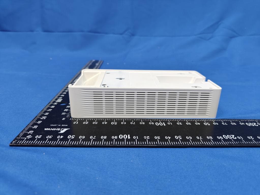
Click to zoom
Application Details
- Equipment Class
- DTS - Digital Transmission System
- Date of Grant
- Nov 18, 2025
- Application Purpose
- Original Equipment
- Equipment Note
- BE11000 Wall Plate Wi-Fi 7 Access Point
- Frequency Range
- 2402.00000000 - 2480.00000000
- Company
- TP-Link Systems Inc.
- Country
- United States
Documents & Files
Document Text
Text extracted from the exhibit documents filed with the FCC. Open a document above to read the original.
Users Manual
Quick Installation Guide Wall Plate Access Point Note: EAP775-Wall is used as an example throughout the guide. Images may differ from your actual product. ©2025 TP-Link 7100001591 REV1.0.0 Scan for EAP Start Guide 1234 1234 Note: This equipment shall be installed at a height of less than 2 meters. Package ContentsInstallation Notes: 1. Accessories may vary by region and model. 2. If you want to paint the cover, remove the cover from the EAP body before painting. Choose the accessory screws that fit your junction box. Compatible wall junctions: Note: For simplicity, this guide uses a Single Gang US wall junction box for demonstration. Note: Reinforced or irregularly-designed network cables may not support this cable routing option. Φ≤6.5 mm 40–43.6 mm ≤40 mm Φ≤6.5 mm 40–43.6 mm ≤40 mm Guide 1×1×1× Option 1 Option 2 2 1 2× Φ 7.6 mm (19/64 in) 1× Φ 25 mm (63/64 in) 1× 1× EAP & Paintable Cover Option 1 Option 2 Option 3 Cover Body 2×2×2× OR 2×2× Standard EU Single Gang USDual Gang US 86 mm Octagon Note: Reinforced or irregularly-designed network cables may not support this cable routing option. Configuration PoE Switch Gateway/Router EAPEAP Configure and manage each EAP on its standalone page. Option 1: Standalone Mode Scan for Standalone Start Guide PoE Switch Gateway/Router On-Premises Controller Omada Central (Cloud-Based) Or Controller EAPEAPEAP Configure and manage EAPs (and other Omada devices) centrally with an Omada Controller. Option 2: Controller Mode Scan for Controller Start Guide More Configurations For more configurations, refer to the User Guides of the Omada Controller and Omada Access Points at: https://support.omadanetworks.com/document/ Omada App With the TP-Link Omada app, you can access and manage your Omada devices at a local site or remotely with a tap of your phone. Scan for OmadaOmada or Safety Information • Keep the device away from water, fire, humidity or hot environments. • Do not attempt to disassemble, repair, or modify the device. If you need service, please contact us. • Do not use the device where wireless devices are not allowed. • This device can be powered only by equipments that comply with Power Source Class 2 (PS2) or Limited Power Source (LPS) defined in the standard of IEC 62368-1. • The PoE ports shall not be used to charge lithium batteries or devices supplied by lithium batteries. TP-Link hereby declares that the Access Point is in compliance with the essential requirements and other relevant provisions of directives 2014/53/EU, 2011 /65/EU and (EU) 2015/863. The original EU Declaration of Conformity may be found at https://www.tp-link.com/en/support/ce/ TP-Link hereby declares that the Access Point is in compliance with the essential requirements and other relevant provisions of the Radio Equipment Regulations 2017. The original UK Declaration of Conformity may be found at https://www.tp-link.com/support/ukca/ The EAP will be locked after installed. To uninstall, remove the cover and unlock with the provided L-Key. Appendix For details on the warranty period, policy, and procedures, visit https://support.omadanetworks.com/warranty-services/. Warranty Support For technical support, user guides, and other information, please visit https://support.omadanetworks.com/, or simply scan the QR code. More Resources Main Site https://www.omadanetworks.com/ https://support.omadanetworks.com/video/ https://support.omadanetworks.com/document/ https://support.omadanetworks.com/product/ https://support.omadanetworks.com/contact-support/ Video Center Product Support Documents Technical Support 1234 Option 3 2 1 2× Φ 7.6 mm (19/64 in) Cover Body 2 3 1 Cover Body Body Cover
Users Manual
© 2025 TP-Link 1910013239 REV2.2.0 Regulatory Compliance Wall Plate EAP For Class B EAP with no adapter: FCC Compliance Information Statement Product Name: Omada EAP Model Number: EAP225-Wall / EAP235-Wall / EAP615-Wall / EAP655-Wall / EAP725-Wall / EAP775-Wall / EAP615GP-Wall / EAP625GP-Wall / EAP673-Extender Responsible party: TP-Link Systems Inc. Address: 10 Mauchly, Irvine, CA 92618 Website: https://www.tp-link.com/us/ Tel: +1 626 333 0234 Fax: +1 909 527 6804 E-mail: [email protected] This equipment has been tested and found to comply with the limits for a Class B digital device, pursuant to part 15 of the FCC Rules. These limits are designed to provide reasonable protection against harmful interference in a residential installation. This equipment generates, uses and can radiate radio frequency energy and, if not installed and used in accordance with the instructions, may cause harmful interference to radio communications. However, there is no guarantee that interference will not occur in a particular installation. If this equipment does cause harmful interference to radio or television reception, which can be determined by turning the equipment off and on, the user is encouraged to try to correct the interference by one or more of the following measures: •Reorient or relocate the receiving antenna. •Increase the separation between the equipment and receiver. •Connect the equipment into an outlet on a circuit different from that to which the receiver is connected. •Consult the dealer or an experienced radio/ TV technician for help. This device complies with part 15 of the FCC Rules. Operation is subject to the following two conditions: 1) This device may not cause harmful interference. 2) This device must accept any interference received, including interference that may cause undesired operation. Any changes or modifications not expressly approved by the party responsible for compliance could void the user’s authority to operate the equipment. Note: The manufacturer is not responsible for any radio or TV interference caused by unauthorized modifications to this equipment. Such modifications could void the user’s authority to operate the equipment. FCC RF Radiation Exposure Statement: This equipment complies with FCC RF radiation exposure limits set forth for an uncontrolled environment. This device and its antenna must not be co-located or operating in conjunction with any other antenna or transmitter. “To comply with FCC RF exposure compliance requirements, this grant is applicable to only Mobile Configurations. The antennas used for this transmitter must be installed to provide a separation distance of at least 20cm from all persons and must not be colocated or operating in conjunction with any other antenna or transmitter.” For EAP775-Wall: •FCC regulations restrict the operation of this device to indoor use only. •The operation of this device is prohibited on oil platforms, cars, trains, boats, and aircraft, except that operation of this device is permitted in large aircraft while flying above 10,000 feet in the 5.925-6.425 GHz band. •Operation of transmitters in the 5.925-7.125 GHz band is prohibited for control of or communications with unmanned aircraft systems. We, TP-Link Systems Inc., has determined that the equipment shown as above has been shown to comply with the applicable technical standards, FCC part 15. There is no unauthorized change is made in the equipment and the equipment is properly maintained and operated. Issue Date: 2025-10-10 CE Mark Warning OPERATING FREQUENCY (the maximum transmitted power) For EAP115-Wall: 2412MHz—2472MHz (20dBm) For EAP225-Wall / EAP230-Wall / EAP235-Wall: 2412MHz—2472MHz (20dBm) 5150MHz—5250MHz (23dBm) For EAP615-Wall / EAP650-Wall / EAP655-Wall / EAP720-Wall / EAP725-Wall / EAP615GP-Wall / EAP625GP-Wall / EAP673-Extender: 2400 MHz -2483.5 MHz (20dBm) 5150MHz—5250MHz (23dBm) 5250 MHz -5350 MHz (23dBm) 5470 MHz -5725 MHz (30dBm) For EAP775-Wall: 2400 MHz -2483.5 MHz (20dBm) 5150MHz—5250MHz (23dBm) 5250 MHz -5350 MHz (23dBm) 5470 MHz -5725 MHz (30dBm) 5945MHz -6425 MHz (23dBm) EU Declaration of Conformity For EAP673-Extender, EAP615GP-Wall / EAP625GP-Wall, and APs with adapters: TP-Link hereby declares that the Access Point is in compliance with the essential requirements and other relevant provisions of directives 2014/53/EU, 2009/125/EC, 2011/65/EU and (EU)2015/863. For other APs: TP-Link hereby declares that the Access Point is in compliance with the essential requirements and other relevant provisions of directives 2014/53/EU, 2011/65/EU and (EU)2015/863. The original EU Declaration of Conformity may be found at https://www.tp-link.com/en/ce. RF Exposure Information This device meets the EU requirements (2014/53/EU Article 3.1a) on the limitation of exposure of the general public to electromagnetic fields by way of health protection. The device complies with RF specifications when the device used at 20 cm from your body. National Restrictions For EAP225-Wall / EAP230-Wall / EAP235-Wall / EAP615-Wall / EAP650-Wall / EAP655-Wall / EAP720-Wall / EAP725-Wall / EAP615GP-Wall / EAP625GP-Wall / EAP673-Extender: Attention: This device may only be used indoors in all EU member states, EFTA countries and Northern Ireland. Frequency band: 5150 - 5250 MHz: Indoor use: Inside buildings only. Installations and use inside road vehicles and train carriages are not permitted. Limited outdoor use: If used outdoors, equipment shall not be attached to a fixed installation or to the external body of road vehicles, a fixed infrastructure or a fixed outdoor antenna. Use by unmanned aircraft systems (UAS) is limited to within the 5170 - 5250 MHz band. Frequency band: 5250 - 5350 MHz: Indoor use: Inside buildings only. Installations and use in road vehicles, trains and aircraft are not permitted. Outdoor use is not permitted. Frequency band: 5470 - 5725 MHz: Installations and use in road vehicles, trains and aircraft and use for unmanned aircraft syste…
Text truncated - open the document above for the full version.
RF Exposure Info
MRT Technology (Taiwan) Co., Ltd Report No.: 2509TW0116-U5 Phone: +886-3-3288388 Report Version 1.0 Web: www.mrt-cert.com Issue Date: 2025-10-23 Page Number: 1 of 15 RF Exposure Evaluation Declaration FCC ID : 2BH7FEAP775WALL Applicant : TP-Link Systems Inc. Application Type : Certification Product : BE11000 Wall Plate Wi-Fi 7 Access Point Model No. : EAP775-Wall Brand Name : tp-link FCC Rule Part(s) : FCC Part 2.1091 FCC Classification : Digital Transmission System (DTS) Unlicensed National Information Infrastructure (NII) 15E 6GHz Low Power Indoor Access Point (6ID) 15E 6GHz Subordinate Indoor Device (6PP) Received Date : September 26, 2025 Test By : ( Owen Tsai ) Reviewed By : ( Paddy Chen ) Approved By : ( Chenz Ker) The test results relate only to the samples tested. The test results shown in the test report are traceable to the national/international standards through the calibration of the equipment and evaluated measurement uncertainty herein. The test report shall not be reproduced except in full without the written approval of MRT Technology (Taiwan) Co., Ltd. Report No.: 2509TW0116-U5 Page Number: 2 of 15 Revision History Report No. Version Description Issue Date Note 2509TW0116-U5 1.0 Original Report 2025-10-23 Report No.: 2509TW0116-U5 Page Number: 3 of 15 CONTENTS Description Page 1. INTRODUCTION ................................................................................................................... 5 1.1. Scope ........................................................................................................................ 5 1.2. MRT Test Location .................................................................................................... 5 2. PRODUCT INFORMATION ................................................................................................... 6 2.1. Feature of Equipment under Test .............................................................................. 6 2.2. Description of Available Antennas .............................................................................. 7 2.3. Device Classification .................................................................................................10 2.4. Applied Standards ....................................................................................................10 3. RF Exposure Evaluation .................................................................................................... 11 3.1. Limits ........................................................................................................................ 11 3.2. MPE Exemptions ......................................................................................................12 3.3. Test Result of RF Exposure Evaluation .....................................................................15 Report No.: 2509TW0116-U5 Page Number: 4 of 15 General Information Applicant TP-Link Systems Inc. Applicant Address 10 Mauchly, Irvine, CA 92618 Manufacturer TP-Link Systems Inc. Manufacturer Address 10 Mauchly, Irvine, CA 92618 Test Site MRT Technology (Taiwan) Co., Ltd Test Site Address No. 38, Fuxing Second Rd., Guishan Dist., Taoyuan City 333, Taiwan (R.O.C) MRT FCC Registration No. 291082 Test Device Serial No. N/A Production Pre-Production Engineering Test Facility / Accreditations 1. MRT facility is a FCC registered (Reg. No. 291082) test facility with the site description report on file and is designated by the FCC as an Accredited Test Firm. 2. MRT facility is an IC registered (MRT Reg. No. 21723) test laboratory with the site description on file at Industry Canada. 3. MRT Lab is accredited to ISO 17025 by the Taiwan Accreditation Foundation (TAF Cert. No. 3261) in EMC, Telecommunications and Radio testing for FCC (Designation Number: TW3261), Industry Canada, EU and TELEC Rules. Report No.: 2509TW0116-U5 Page Number: 5 of 15 1. INTRODUCTION 1.1. Scope Measurement and determination of electromagnetic emissions (EMC) of radio frequency devices including intentional and/or unintentional radiators for compliance with the technical rules and regulations of the Federal Communications Commission and the Innovation, Science and Economic Development Canada and Certification and Engineering Bureau. 1.2. MRT Test Location The map below shows the location of the MRT LABORATORY, its proximity to the Taoyuan City. These measurement tests were conducted at the MRT Technology (Taiwan) Co., Ltd. Facility located at No.38, Fuxing 2nd Rd., Guishan Dist., Taoyuan City 33377, Taiwan (R.O.C). Report No.: 2509TW0116-U5 Page Number: 6 of 15 2. PRODUCT INFORMATION 2.1. Feature of Equipment under Test Product Name BE11000 Wall Plate Wi-Fi 7 Access Point Model No. EAP775-Wall Specification WLAN: 802.11a/b/g/n/ac/ax/be WPAN: Bluetooth Single Mode Power Supply 802.3at PoE Report No.: 2509TW0116-U5 Page Number: 7 of 15 2.2. Description of Available Antennas 1. BLE Antenna Antenna Type Frequency Band (MHz) T X Paths Number of spatial streams Max Antenna Gain (dBi) Beamforming Directional Gain(dBi) CDD Directional Gain (dBi) IFA 2402 ~ 2480 1 1 1.00 -- -- -- 2. Wi-Fi Antenna Antenna Type Frequency Band (MHz) T X Paths Number of spatial streams Max Antenna Gain (dBi) Beamforming Directional Gain(dBi) CDD Directional Gain (dBi) Ant1 Ant2 For Power For PSD Dipole 2412 ~ 2462 2 1 5.07 4.91 4.90 1.90 4.90 Remark: 1. The device supports CDD Mode and Beamforming mode, details refer to the table as below. 2. CDD signals are correlated, the directional gain as follows, When N SS =1, for power measurements: the max directional gain (each angle) = 10 log[(10 G1 /10 + 10 G2 /10 + ... + 10 GN /10 ) /N ANT ] For power spectral density (PSD) measurements: the max directional gain (each angle) = 10 log[(10 G1 /20 + 10 G2 /20 + ... + 10 GN /20 ) 2 /N ANT ] When N SS =2, the max directional gain (each angle) = 10 log[(10 G1 /10 + 10 G2 /10 + ... + 10 GN /10 ) /N ANT ] 3. Beamforming signals are correlated, the directional gain as follows, the max dir…
Text truncated - open the document above for the full version.
Test Setup Photos
Report No.: R25S1056092-UT 1 of 4 RF Test Setup Photograph Description: Front View of Conducted Spurious Emissions Test Setup (WZ-SR2) Description: Side View of Conducted Spurious Emissions Test Setup (WZ-SR2) Report No.: R25S1056092-UT 2 of 4 Description: Radiated Spurious Emissions Test Setup for Below 30 MHz (WZ-AC1) Description: Radiated Spurious Emissions Test Setup for Below 1 GHz (WZ-AC1) Report No.: R25S1056092-UT 3 of 4 Description: Radiated Spurious Emissions Test Setup for Above 1 GHz (WZ-AC1) Description: Radiated Spurious Emissions Test Setup for Above 18 GHz (WZ-AC1) Report No.: R25S1056092-UT 4 of 4 Description: Radiated Restricted Band Edge Test Setup (WZ-AC2)
Test Setup Photos
Report No.: 2509TW0116-UT 1 of 5 RF Test Photograph Description: Front View of Conducted Emission Test Setup Description: Back View of Conducted Emission Test Setup Report No.: 2509TW0116-UT 2 of 5 Description: Radiated Emission Test Setup for below 1GHz Description: Radiated Emission Test Setup for above 1GHz (BLE & Wi-Fi 2.4G) Report No.: 2509TW0116-UT 3 of 5 Description: Radiated Emission Test Setup for above 1GHz (Wi-Fi 5G) Description: Radiated Emission Test Setup for 18GHz~40GHz Report No.: 2509TW0116-UT 4 of 5 Description: Radiated Emission Test Setup for 9kHz~30MHz Report No.: 2509TW0116-UT 5 of 5 Description: Conducted Measurement Test Setup Description: DFS Test Setup
Test Report
MRT Technology (Taiwan) Co., Ltd Report No.: 2509TW0116-U1 Phone: +886-3-3288388 Report Version: 1.0 Fax: +886-3-3288918 Issue Date: 2025-10-23 Web: www.mrt-cert.com Page Number: 1 of 93 FCC ID : 2BH7FEAP775WALL APPLICANT : TP-Link Systems Inc. Application Type : Certification Product : BE11000 Wall Plate Wi-Fi 7 Access Point Model No. : EAP775-Wall Brand Name : tp-link FCC Classification : Digital Transmission System (DTS) FCC Rule Part(s) : Part 15.247 Test Procedure(s) : ANSI C63.10-2020+Cor 1-2023+C63.10a-2024 + Errata to C63.10a-2024 Received Date : September 26, 2025 Test Date : October 1, 2025~ October 7, 2025 MEASUREMENT REPORT Tested By : ( Kaunaz Lee ) Reviewed By : ( Paddy Chen ) Approved By : ( Chenz Ker) The test results only relate to the tested sample. This equipment has been shown to be capable of compliance with the applicable technical standards as indicated in the measurement report and was tested in accordance with the measurement procedures specified in ANSI C63.10. Test results reported herein relate only to the item(s) tested. The test report shall not be reproduced except in full without the written approval of MRT Technology (Taiwan) Co., Ltd. Report No.: 2509TW0116-U1 Page Number: 2 of 93 Revision History Report No. Version Description Issue Date Note 2509TW0116-U1 1.0 Original Report 2025-10-23 Report No.: 2509TW0116-U1 Page Number: 3 of 93 CONTENTS Description Page 1. INTRODUCTION ..................................................................................................................... 6 1.1. Scope .................................................................................................................................... 6 1.2. MRT Test Location ................................................................................................................ 6 2. PRODUCT INFORMATION ..................................................................................................... 7 2.1. Equipment Description .......................................................................................................... 7 2.2. Product Specification Subjective to this Standard .................................................................. 7 2.3. Test Mode ............................................................................................................................. 7 2.4. Operation Frequency / Channel List ...................................................................................... 8 2.5. Test Configuration ................................................................................................................. 9 2.6. Test System Details ............................................................................................................ 10 2.7. Test Software ...................................................................................................................... 10 2.8. Duty Cycle ........................................................................................................................... 11 2.9. EMI Suppression Device(s)/Modifications ........................................................................... 12 2.10. Labeling Requirements.................................................................................................... 12 3. DESCRIPTION of TEST ........................................................................................................ 13 3.1. Evaluation Procedure .......................................................................................................... 13 3.2. AC Line Conducted Emissions ............................................................................................ 13 3.3. Radiated Emissions ............................................................................................................ 14 4. ANTENNA REQUIREMENTS ................................................................................................ 15 5. TEST EQUIPMENT CALIBRATION DATE ............................................................................ 16 6. MEASUREMENT UNCERTAINTY ......................................................................................... 17 7. TEST RESULT ...................................................................................................................... 18 7.1. Summary ............................................................................................................................. 18 7.2. 6dB Bandwidth Measurement ............................................................................................. 19 7.2.1. Test Limit ......................................................................................................................... 19 7.2.2. Test Procedure used ....................................................................................................... 19 7.2.3. Test Setting ..................................................................................................................... 19 7.2.4. Test Setup ....................................................................................................................... 19 7.2.5. Test Result ...................................................................................................................... 20 7.3. Output Power Measurement ................................................................................................ 24 7.3.1. Test Limit ......................................................................................................................... 24 7.3.2. Test Procedure Used ....................................................................................................... 24 7.3.3. Test Setting ..................................................................................................................... 24 7.3.4. Test Setup ....................................................................................................................... 24 7.…
Text truncated - open the document above for the full version.
Test Report
Copyright © 2024 TP-Link Systems Inc. All rights reserved FCC Composite Gain Test Report TP-Link Systems Inc. 10 Mauchly, Irvine, CA 926187 Copyright © 2024 TP-Link Systems Inc. All rights reserved Copyright © 2024 By TP-Link Systems Inc. All rights reserved. The drawings, specifications and the data contained in this document are exclusively the property of TP-Link Systems Inc. The information is intended for internal use only and is subject to change without any notice. With no written permission from TP-Link Systems Inc. this document, in parts or as a whole, shall not be reproduced, copied, or used in any form or by any means to make any derivatives such as translation, transformation, or adaptation, for any purpose whatever. is a registered trademark of TP-Link Systems Inc. Other brands and product names mentioned herein are trademarks or registered trademarks of their respective holders. Warning This document is intended for internal use only. A Non-Disclosure Agreement (NDA) approved by Chief Technology Officer (CTO) is required to release this document under any circumstances. Basic Information EUT Description: BE11000 Wall Plate Wi-Fi 7 Access Point Brand Name: tp-link Model Name: EAP775-Wall Tested By: Shao Jinwei Date: 2025/08/28 Copyright © 2024 TP-Link Systems Inc. All rights reserved CONTENTS 1 Operation Mode and Antenna Information ........................................................................................ 5 1.1 EUT Operation Mode ...................................................................................................................... 5 1.2 Antenna Information ....................................................................................................................... 5 1.3 Test Frequency ................................................................................................................................ 6 2 Test System ............................................................................................................................................. 6 2.1 Test Equipment ................................................................................................................................ 6 2.2 Test Software ................................................................................................................................... 6 3 Test Summary ........................................................................................................................................ 7 3.1 Measurement Environment ............................................................................................................. 7 3.2 Measurement Quantity .................................................................................................................... 9 3.3 Test Method ..................................................................................................................................... 9 3.4 Directional Gain (Nss=1) Calculations ......................................................................................... 10 3.5 Directional Gain (Nss=N ant ) Calculations ..................................................................................... 11 3.6 Test Procedure ............................................................................................................................... 11 4 Measured Value and Maximum Gain Positions................................................................................ 13 4.1 Antenna Number ........................................................................................................................... 13 4.2 2G .................................................................................................................................................. 13 4.2.1 DG_1SS Max Value Position ................................................................................................ 13 4.2.2 DG_1SS Max Value Position Calculation ............................................................................. 13 4.2.3 DG_NSSmax Max Value Position ......................................................................................... 14 4.2.4 DG_NSSmax Max Value Position Calculation ..................................................................... 14 4.3 5G .................................................................................................................................................. 14 4.3.1 DG_1SS Max Value Position ................................................................................................ 14 4.3.2 DG_1SS Max Value Position Calculation ............................................................................. 14 4.3.3 DG_NSSmax Max Value Position ......................................................................................... 15 4.3.4 DG_NSSmax Max Value Position Calculation ..................................................................... 15 4.4 6G .................................................................................................................................................. 15 4.4.1 DG_1SS Max Value Position ................................................................................................ 15 4.4.2 DG_1SS Max Value Position Calculation ............................................................................. 16 4.4.3 DG_NSSmax Max Value Position ......................................................................................... 16 4.4.4 DG_NSSmax Max Value Position Calculation ..................................................................... 16 5 Test and Calculate Result ................................................................................................................... 16 5.1 Peak Antenna Gain(Single) ...................................................................................................... 16 Copyright © 2024 TP-Link Systems Inc. All rights reserved 5.2 DG_1SS Calculate Result .…
Text truncated - open the document above for the full version.
Test Report
Product Model: EAP775-Wall Manufacturer: TP-Link Systems Inc. Test Date: 2025.9.2 Tested By: Shao Jinwei TP-Link Systems Inc. 10 Mauchly, Irvine, CA 92618 Index 1. Antenna Distribution ........................................................................................ 3 2. Electrical Characteristics ................................................................................ 3 3. Gain and Radiation Pattern ............................................................................. 4 3.1 Measurement Procedure ......................................................................................... 4 3.2 Test Setup ............................................................................................................... 5 3.3 S Parameter Test Data ............................................................................................ 6 3.4 Antenna Peak Gain .............................................................................…
Text truncated - open the document above for the full version.
Contact Information
Applicant
Sarah Wang
[email protected]Fax: 6263330234
Technical Contact
MRT Technology (Suzhou) Co., LtdMarlin Chen
[email protected]Fax: 86-512-66308368
D8 Building, Youxin Industrial Park, · Suzhou, 215104 · China
Test Firm
MRT Technology (Taiwan) Co.,LtdChenz Ker
[email protected]Fax: +886-3-328-8918
Technical Specifications
| # | Rule Parts | Frequency Range | Power Output |
|---|---|---|---|
| 1 | 15C | 2.40 GHz - 2.48 GHz | 50.90 mW |
| 2 | 15C | 2.41 GHz - 2.46 GHz | 222.30 mW |