2BH7FER703WP4GOD4G+Cat6 AX3000 Outdoor/Indoor Gateway
TP-Link Systems Inc.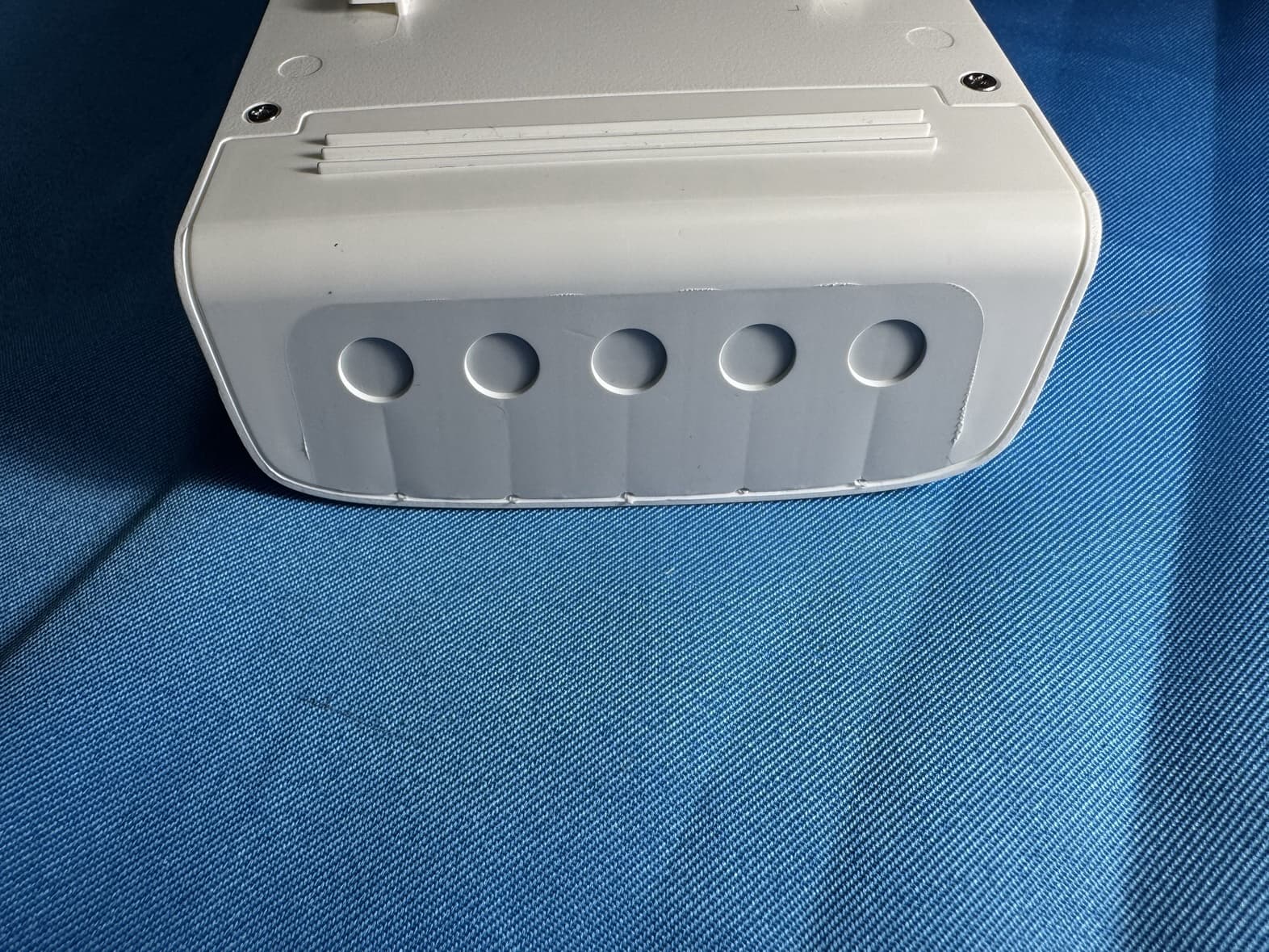
Click to zoom
Application Details
- Equipment Class
- NII - Unlicensed National Information Infrastructure TX
- Date of Grant
- Dec 05, 2025
- Application Purpose
- Original Equipment
- Equipment Note
- 4G+Cat6 AX3000 Outdoor/Indoor Gateway
- Frequency Range
- 5180.00000000 - 5240.00000000
- Company
- TP-Link Systems Inc.
- Country
- United States
Documents & Files
Document Text
Text extracted from the exhibit documents filed with the FCC. Open a document above to read the original.
Users Manual
Installation Guide 4G+Cat6 AX3000 Outdoor/Indoor Gateway Mounting Note: The image may differ from the actual product. © 2024 TP-Link 7106511411 REV1.0.0 Hardware Connection 1. Power on the gateway. Software Configuration 3 The gateway supports two configuration options: Standalone Mode: Configure and manage the gateway by itself. Controller Mode: Configure and manage network devices centrally. It is recommended in large-scale networks, which consist of a large number of devices such as access points, switches, and gateways. Option 1: Standalone Mode Note: 1. When the gateway is managed by a controller, configurations of the gateway will be overridden by the controller. 2. For the detailed configurations, refer to the User Guide of the gateway and the controller. The guides can be found on the download center of our official website: https://www.tp-link.com/support/download/. 4G Gateway Connect a PSE device to the PoE IN port. Option 2: Via a PSE device Connect the power adapter into the power port of the gateway. Option 1: Via power adapter (not provided) PSE Device (e.g. PoE Switch, PoE Injector) 3. (Optional) Connect Powered Devices. Connect the Powered Devices to the PoE OUT ports for power supply and data transmission. 2. Connect to the internet. On: Wireless networking is enabled. Off: Wireless networking is disabled. Yellow On: Running at 1000 Mbps, but no activity. Yellow Flashing: Running at 1000 Mbps, and transmitting or receiving data. Green On: Running at 1000Mbps with providing PoE Power, but no activity. Green Flashing: Running at 1000Mbps with providing PoE Power, and transmitting or receiving data. Off: Not running or no device is connected to the corresponding port. Yellow On: Running at 1000 Mbps and be powered by 802.3at or Passive PoE or DC Input, but no activity. Yellow Flashing: Running at 1000 Mbps and be powered by 802.3at or Passive PoE or DC Input, and transmitting or receiving data. Green On: Running at 1000Mbps and be powered by 802.3bt, but no activity. Green Flashing: Running at 1000Mbps and be powered by 802.3bt, and transmitting or receiving data. Off: Not running or no device is connected to the corresponding port. 2&3 (PoE OUT) 1 (PoE IN) WLAN LEDIndication Slow Flashing: System is running normally. Quick Flashing: The gateway is being reset. On/Off: System is starting up or running abnormally. Flashing: SIM card is trying to connect to the internet. On: Indicates the signal strength the gateway received from the mobile internet. More LEDs indicate a better signal strength. Off: No mobile internet signal. 4G Signal SYS LED Indication Wireless Internet Connection Wired Internet Connection The gateway can be powered via a power adapter or a PSE device (such as a PoE switch) which complies with Power Source Class 2 ( PS2) or Limited Power Source (LPS) of IEC 62368-1. Option 1 Option 2 Note: The device can be pole-mounted or wall-mounted. Follow the steps below for the appropriate installation and make sure the device is installed with its ports facing down. Method 1: Pole Mounting 1. Attach the provided 4G antennas. 1. Attach the provided 4G antennas. 2. Lead the end of the pole mounting strap through the back of the mounting bracket. 3. Fix the mounting bracket on the pole and fasten the strap, then secure the device into the mounting bracket as shown below. Method 2: Wall Mounting 2. Attach the mounting template and drill four 6 mm holes, insert the anchors into the holes, align the bracket to the anchors and drive the self-tapping screws into the anchors through the bracket. 3. Align the mounting bracket and the device, and secure the device into the mounting bracket as shown below. Mounting Bracket ScrewsAnchors Position Label IP CameraAPIP Phone PoE OUT (2, 3) Powered Device (PD) a. With the gold contacts facing up, insert the nano SIM card into the slot until you hear a click. b. Wait until the SYS LED flashes slowly and the 4G Signal LED turns solid, indicating the gateway is connected to the internet. Note: For better internet connection, make sure 2 or 3 Signal LEDs are lit. Otherwise, try relocating the gateway to a spot that may receive a stronger mobile network signal. Note: 1. The PoE OUT ports can also be connected to non-PoE devices, but only transmit data. 2. Maximum PoE power is 30 W for each PoE port, and 27W/45 W PoE power budget for all PoE ports when powered by 802.3bt (type 3, 60 W)/ 802.3bt (type 4, 90 W) respectively. 3. PoE budget calculations are based on laboratory testing. Actual PoE power budget is not guaranteed and will vary as a result of client limitations and environmental factors. 4. When the gateway is powered by DC input, it cannot supply power to its connected PD devices. Note: You can also connect the gateway to the internet via Ethernet, but ports 1, 2, and 3 are LAN ports by default and you will need to configure the desired port as a WAN port via the management page first. Safety Information Do not attempt to disassemble, repair, or modify the device. If you need service, please contact us. Do not use the device where wireless devices are not allowed. Do not use damaged charger or USB cable to charge the device. Do not use any other chargers than those recommended. Adapter shall be installed near the equipment and shall be easily accessible. Place the device with its bottom surface downward. Keep the device away from fire or hot environments. DO NOT immerse in water or any other liquid. TP-Link hereby declares that the device is in compliance with the essential requirements and other relevant provisions of the Radio Equipment Regulations 2017. The original UK declaration of conformity may be found at https://www.tp-link.com/support/ukca/. TP-Link hereby declares that the device is in compliance with the essential requirements and other relevant provisions of directives 2014/53/EU, 2011/65/EU and (EU) 2015/863. The original EU declaration of conformity may be found at https://www.tp-link.com/en/support/ce/. EU Declara…
Text truncated - open the document above for the full version.
Users Manual
Regulatory Compliance Omada 4G+Cat6 AX3000 Outdoor/Indoor Gateway © 2024 TP-Link 1910013787 REV1.0.0 CE Mark Warning This is a class A product. In a domestic environment, this product may cause radio interference, in which case the user may be required to take adequate measures. OPERATING FREQUENCY(the maximum transmitted power) 2400 MHz -2483.5 MHz(20dBm) 5150 MHz -5250 MHz(23dBm) 5250 MHz -5350 MHz (23dBm) 5470 MHz -5725 MHz (30dBm) WCDMA Band 1/3/8 (24dBm+1.7/‐3.7dB) LTE Band 1/3/7/8/20/28/38/40(23dBm+2.7/‐2.7 dB) EU Declaration of Conformity TP-Link hereby declares that the device is in compliance with the essential requirements and other relevant provisions of directives 2014/53/EU, 2011 /65/EU and (EU) 2015/863. The original EU declaration of conformity may be found at https://www.tp-link.com/en/ce/ RF Exposure Information This device meets the EU requirements (2014/53/EU Article 3.1a) on the limitation of exposure of the general public to electromagnetic fields by way of health protection. The device complies with RF specifications when the device used at 20 cm from your body. Frequency band: 5150 - 5250 MHz: Indoor use: Inside buildings only. Installations and use inside road vehicles and train carriages are not permitted. Limited outdoor use: If used outdoors, equipment shall not be attached to a fixed installation or to the external body of road vehicles, a fixed infrastructure or a fixed outdoor antenna. Use by unmanned aircraft systems (UAS) is limited to within the 5170 - 5250 MHz band. Frequency band: 5250 - 5350 MHz: Indoor use: Inside buildings only. Installations and use in road vehicles, trains and aircraft are not permitted. Outdoor use is not permitted. Frequency band: 5470 - 5725 MHz: Installations and use in road vehicles, trains and aircraft and use for unmanned aircraft systems (UAS) are not permitted. National restrictions ATBEBGCHCYCZDEDK EEELESFIFRHRHUIE ISITLILTLULVMTNL NOPLPTROSESISKUK(NI) UKCA Mark UK Declaration of Conformity TP-Link hereby declares that the device is in compliance with the essential requirements and other relevant provisions of the Radio Equipment Regulations 2017. The original UK declaration of conformity may be found at https://www.tp-link.com/support/ukca/ National Restrictions Attention: In Great Britain, the operation in the frequency range 5150MHz - 5350MHz is only permitted indoors. UK Korea Warning Statements: 당해 무선설비는 운용중 전파혼신 가능성이 있음. NCC Notice & BSMI Notice: 注意! 取得審驗證明之低功率射頻器材,非經核准,公司、商號或使用者均不得擅自變更頻率、加大 功率或變更原設計之特性及功能。 低功率射頻器材之使用不得影響飛航安全及干擾合法通信;經發現有干擾現象時,應立即停 用,並改善至無干擾時方得繼續使用。 前述合法通信,指依電信管理法規定作業之無線電通信。 低功率射頻器材須忍受合法通信或工業、科學及醫療用電波輻射性電機設備之干擾。 應避免影響附近雷達系統之操作。 高增益指向性天線只得應用於固定式點對點系統。 • BSMI Notice 安全諮詢及注意事項 ■ 請 使用原裝電源供應器或只能按照本產品注明的電源類型使用本產品。 ■ 清潔本產品之前請先拔掉電源線。請勿使用液體、噴霧清潔劑或濕布進行清潔。 ■ 注 意防潮,請勿將水或其他液體潑灑到本產品上。 ■ 插槽與開口供通風使用,以確保本產品的操作可靠並防止過熱,請勿堵塞或覆蓋開口。 ■ 請 勿將本產品置放於靠近熱源的地方。除非有正常的通風,否則不可放在密閉位置中。 ■ 不要私自拆開機殼或自行維修,如產品有故障請與原廠或代理商聯繫。 ■ 電源供應器应使用在环境温度低於或等於40°C的室內。 ■ 警告:為避免電磁干擾,本產品不應安裝或使用於住宅環境。 限用物質含有情況標示聲明書 單元 限用物質及其化學符號 鉛 Pb 汞 Hg 鎘 Cd 六價鉻 Cr +6 多溴聯苯 PBB 多溴二苯醚 PBDE PCB○○○○○○ 外殼○○○○○○ 天線○○○○○○ 其他及其配件—○○○○○ 備考1. "超出0.1 wt %" 及 "超出0.01 wt %" 係指限用物質之百分比含量超出百分比含量基準值。 備考2."○"係指該項限用物質之百分比含量未超出百分比含量基準值。 備考3."—" 係指該項限用物質為排除項目。 Продукт сертифіковано згідно с правилами системи УкрСЕПРО на відповідність вимогам нормативних документів та вимогам, що передбачені чинними законодавчими актами України. Safety Information ■Do not attempt to disassemble, repair, or modify the device. If you need service, please contact us. ■Do not use the device where wireless devices are not allowed. ■Do not use damaged charger or USB cable to charge the device. ■Do not use any other chargers than those recommended. ■Adapter shall be installed near the equipment and shall be easily accessible. ■Keep the device away from fire or hot environments. DO NOT immerse in water or any other liquid. ■A dapter should be used indoors where the ambient temperature is lower than or equal to 40 ̊C. ■ The operating temperature for the device shall be within -30 ̊C to 60 ̊C. ■T his product uses radios and other components that emit electromagnetic fields. Electromagnetic fields and magnets may interfere with pacemakers and other implanted medical devices. Always keep the product and its power adapter more than 15 cm (6 inches) away from any pacemakers or other implanted medical devices. If you suspect your product is interfering with your pacemaker or any other implanted medical device, turn off your product and consult your physician for information specific to your medical device. Please read and follow the above safety information when operating the device. We cannot guarantee that no accidents or damage will occur due to improper use of the device. Please use this product with care and operate at your own risk. Explanation of the symbols on the product label Note: The product label can be found at the bottom of the product and its I.T.E. power supply. Symbols may vary from products. Symbol Explanation Class II equipment Class II equipment with functional earthing Alternating current Direct current Polarity of d.c. power connector For indoor use only Dangerous voltage Caution, risk of electric shock Energy efficiency Marking Protective earth Earth Frame or chassis Functional earthing Caution, hot surface Caution Operator's manual Stand-by "ON"/"OFF" (push-push) Fuse Fuse is used in neutral N RECYCLING This product bears the selective sorting symbol for Waste electrical and electronic equipment (WEEE). This means that this product must be handled pursuant to European directive 2012/19/EU in order to be recycled or dismantled to minimize its impact on the environment. User has the choice to give his product to a competent recycling organization or to the retailer when he buys a new electrical or electronic equipment. Caution, avoid listening at high volume levels for long periods Disconnection, all power plugs mSwitch of mini-gap construction μ Switch of micro-gap construction (for US version) Switch…
Text truncated - open the document above for the full version.
RF Exposure Info
Report No.: BTL-FCCP-4-2409G003A Report Version: R01 Page 1 of 6 FCC RF EXPOSURE REPORT FCC ID: 2BH7FER703WP4GOD Project No. : 2409G003A Equipment : 4G+Cat6 AX3000 Outdoor/Indoor Gateway Brand Name : tp-link Test Model : ER703WP-4G-Outdoor Model Name : ER703WP-4G-Outdoor Hardware Version : v1.20 Software Version : ER703WP-4G-Outdoor_V1_1_0 Applicant : TP-Link Systems Inc. Address : 10 Mauchly, Irvine, CA 92618 Manufacturer : TP-Link Systems Inc. Address : 10 Mauchly, Irvine, CA 92618 Date of Receipt : Mar. 20, 2025 Date of Test : Mar. 27, 2025 ~ Aug. 29, 2025 Issued Date : Nov. 28, 2025 Test Sample : Engineering Sample No.: DG2025032077 for WIFI. Standard(s) : FCC Guidelines for Human Exposure IEEE C95.1 & FCC Part 2.1091 FCC Title 47 Part 2.1091 & KDB 447498 D01 v06 The above equipment has been tested and found compliance with the requirement of the relative standards by BTL Inc. (Dongguan) Prepared by : Chella Zheng Approved by : Chay Cai No.3, Jinshagang 1st Road, Dalang, Dongguan, Guangdong People’s Republic of China. Te l : + 8 6-769-8318-3000 Web: www.newbtl.com Service mail: [email protected] Report No.: BTL-FCCP-4-2409G003A Report Version: R01 Page 2 of 6 REVISION HISTORY Report No. Version Description Issued Date Note BTL-FCCP-4-2409G003A R00 Original Report. Oct. 17, 2025 Invalid BTL-FCCP-4-2409G003A R01 This report updated beamforming gain in page 3. It is a revision of the report BTL-FCCP-4-2409G003A R00. This is a newly released report, replacing the BTL-FCCP-4-2409G003A R00 report. Nov. 28, 2025 Valid Report No.: BTL-FCCP-4-2409G003A Report Version: R01 Page 3 of 6 1. MPE CALCULATION METHOD Calculation Method of RF Safety Distance: where: S = power density P = power input to the antenna G = power gain of the antenna in the direction of interest relative to an isotropic radiator R = distance to the center of radiation of the antenna 2. ANTENNA SPECIFICATION For 2.4GHz: Ant. Brand P/N Antenna Type Connector Gain (dBi) 1 tp -link ER703WP –Ant3 Dipole N/A 3 2 tp -link ER703WP –Ant4 Dipole N/A 3.48 Note: 1) This EUT supports CDD, and all antenna gains are not equal, Directional gain = G ANT +Array Gain. For power measurements, Array Gain=0dB (N ANT ≤4), so the Directional gain=3.48. 2) Beamforming Gain: 3dB. 3) The antenna gain and beamforming gain are provided by the manufacturer. For 5GHz: Ant. Brand P/N Antenna Type Connector Gain (dBi) Note 1 tp -link ER703WP –Ant3 Dipole N/A 3.84 UNII-1 2 tp -link ER703WP –Ant4 Dipole N/A 5.08 1 tp -link ER703WP –Ant3 Dipole N/A 3.59 UNII-2A 2 tp -link ER703WP –Ant4 Dipole N/A 5.33 1 tp -link ER703WP –Ant3 Dipole N/A 3.83 UNII-2C 2 tp -link ER703WP –Ant4 Dipole N/A 5.29 1 tp -link ER703WP –Ant3 Dipole N/A 4.47 UNII-3 2 tp -link ER703WP –Ant4 Dipole N/A 4.50 Note: 1) This EUT supports CDD, and all antenna gains are not equal, Directional gain = G ANT +Array Gain. For power measurements, Array Gain=0dB (N ANT ≤4), so the UNII-1 Directional gain=5.08, the UNII-2A Directional gain=5.33, the UNII-2C Directional gain=5.29, the UNII-3 Directional gain=4.50. 2) Beamforming Gain: 3 dB. 3) The antenna gain and beamforming gain are provided by the manufacturer. Report No.: BTL-FCCP-4-2409G003A Report Version: R01 Page 4 of 6 For LTE: Brand P/N Antenna Type Connector Gain (dBi) Note tp -link ER703WP -Ant1 Dipole N/A 1.96 LTE Band 5 (Ant. 1) 2.13 LTE Band 26 (Ant. 1) 2.76 LTE Band 2 (Ant. 1) 2.76 LTE Band 25 (Ant. 1) 2.54 LTE Band 4 (Ant. 1) 1.12 LTE Band 7 (Ant. 1) 0.94 LTE Band 12 (Ant. 1) 2.04 LTE Band 13 (Ant. 1) 0.85 LTE Band 30 (Ant. 1) 1.23 LTE Band 41 (Ant. 1) 2.59 LTE Band 66 (Ant. 1) 0.63 LTE Band 71 (Ant. 1) 1.67 LTE Band 14 (Ant. 1) -0.12 LTE Band 48 (Ant. 1) Note: The antenna gain is provided by the manufacturer. Report No.: BTL-FCCP-4-2409G003A Report Version: R01 Page 5 of 6 3. CALCULATED RESULT For 2.4GHz: Directional gain (dBi) Directional gain (numeric) Max. Output Power (dBm) Max. Output Power (mW) Power Density (S) (mW/cm 2 ) Limit of Power Density (S) (mW/cm 2 ) Test Result 3.48 2.2284 23.89 244.9063 0.08978 1 Complies For 5GHz(UNII-1): Directional gain (dBi) Directional gain (numeric) Max. Output Power (dBm) Max. Output Power (mW) Power Density (S) (mW/cm 2 ) Limit of Power Density (S) (mW/cm 2 ) Test Result 5.08 3.2211 27.29 535.7967 0.28390 1 Complies For 5GHz(UNII-2A): Directional gain (dBi) Directional gain (numeric) Max. Output Power (dBm) Max. Output Power (mW) Power Density (S) (mW/cm 2 ) Limit of Power Density (S) (mW/cm 2 ) Test Result 5.33 3.4119 23.96 248.8857 0.13969 1 Complies For 5GHz(UNII-2C): Directional gain (dBi) Directional gain (numeric) Max. Output Power (dBm) Max. Output Power (mW) Power Density (S) (mW/cm 2 ) Limit of Power Density (S) (mW/cm 2 ) Test Result 5.29 3.3806 23.93 247.1724 0.13746 1 Complies For 5GHz(UNII-3): Directional gain (dBi) Directional gain (numeric) Max. Output Power (dBm) Max. Output Power (mW) Power Density (S) (mW/cm 2 ) Limit of Power Density (S) (mW/cm 2 ) Test Result 4.50 2.8184 29.64 920.4496 0.42674 1 Complies Report No.: BTL-FCCP-4-2409G003A Report Version: R01 Page 6 of 6 For LTE: Band Frequency (MHz) Max. Tune up Power (dBm) Antenna Gain (dBi) Antenna Gain (linear) Output Power to Antenna Power Density (mW/cm 2 ) Power Density Limit (mW/cm 2 ) Te s t Result Band 5 824.7 25 1.96 1.5704 496.5923 0.0817 0.5498 Complies Band 26 (824-849) 824.7 25 2.13 1.6331 516.4164 0.0849 0.5498 Complies Band 2 1850.7 25 2.76 1.8880 597.04 0.0982 1.0000 Complies Band 25 1850.7 25 2.76 1.8880 597.04 0.0982 1.0000 Complies Band 4 1710.7 25 2.54 1.7947 567.54 0.0933 1.0000 Complies Band 7 2502.5 25 1.12 1.2942 409.26 0.0673 1.0000 Complies Band 12 699.7 25 0.94 1.2417 392.6449 0.0646 0.4665 Complies Band 13 779.5 25 2.04 1.5996 505.8247 0.0832 0.5197 Complies Band 30 2307.5 23 0.85 1.2162 242.66 0.0399 1.0000 Complies Band 41 2498.5 25 1.23 1.3274 419.76 0.0690 1.0000 Complies Band 66 1710.7 25 2.59 1.8155 574.12 0.0944 1.0000 Complies Band 71 665.5 25 0.63 1.1561 365.5948 0.0601 0.4437 Complies Ban…
Text truncated - open the document above for the full version.
Test Setup Photos
Report No.: BTL-FCCP-2-2409G003A Report Version: R00 Page 38 of 288 10. EUT TEST PHOTOS AC Power Line Conducted Emissions Test Photos Report No.: BTL-FCCP-2-2409G003A Report Version: R00 Page 39 of 288 Radiated Emissions Test Photos 9 kHz to 30 MHz Report No.: BTL-FCCP-2-2409G003A Report Version: R00 Page 40 of 288 Radiated Emissions Test Photos 30 MHz to 1 GHz Report No.: BTL-FCCP-2-2409G003A Report Version: R00 Page 41 of 288 Radiated Emissions Test Photos Band edge & Harmonic(1 GHz to 18 GHz) Report No.: BTL-FCCP-2-2409G003A Report Version: R00 Page 42 of 288 Radiated Emissions Test Photos Harmonic(18 GHz to 40 GHz) Report No.: BTL-FCCP-2-2409G003A Report Version: R00 Page 43 of 288 Conducted Test Photos Report No.: BTL-FCCP-3-2409G003A Report Version: R00 Page 256 of 257 10. EUT TEST PHOTO Report No.: BTL-FCCP-3-2409G003A Report Version: R00 Page 257 of 257 End of Test Report Ant.1 Ant.2
Test Report
Copyright © 2024 TP-Link Systems Inc. All rights reserved FCC Composite Gain Test Report TP-Link Systems Inc. 10 Mauchly, Irvine, CA 926187 Copyright © 2024 TP-Link Systems Inc. All rights reserved Copyright © 2024 By TP-Link Systems Inc. All rights reserved. The drawings, specifications and the data contained in this document are exclusively the property of TP-Link Systems Inc. The information is intended for internal use only and is subject to change without any notice. With no written permission from TP-Link Systems Inc. this document, in parts or as a whole, shall not be reproduced, copied, or used in any form or by any means to make any derivatives such as translation, transformation, or adaptation, for any purpose whatever. is a registered trademark of TP-Link Systems Inc. Other brands and product names mentioned herein are trademarks or registered trademarks of their respective holders. Wa r n in g This document is intended for internal use only. A Non-Disclosure Agreement (NDA) approved by Chief Technology Officer (CTO) is required to release this document under any circumstances. Basic Information EUT Description: ER703WP-4G-Outdoor Brand Name: tp-link Model Name: ER703WP-4G-Outdoor Tested By: Cui Jiafu Date: 2025/02/25 Copyright © 2024 TP-Link Systems Inc. All rights reserved CONTENTS 1 Operation Mode and Antenna Information ........................................................................................ 4 1.1 EUT Operation Mode ...................................................................................................................... 4 1.2 Antenna Information ....................................................................................................................... 4 1.3 Test Frequency ................................................................................................................................ 5 2 Test System ............................................................................................................................................. 5 2.1 Test Equipment ................................................................................................................................ 5 2.2 Test Software ................................................................................................................................... 5 3 Test Summary ........................................................................................................................................ 6 3.1 Measurement Environment ............................................................................................................. 6 3.2 Measurement Quantity .................................................................................................................... 8 3.3 Test Method ..................................................................................................................................... 8 3.4 Directional Gain Calculations ......................................................................................................... 9 3.5 Test Procedure ............................................................................................................................... 10 4 Measured Value and Maximum Gain Positions ................................................................................ 11 4.1 Antenna Number ........................................................................................................................... 11 4.2 2G .................................................................................................................................................. 11 4.2.1 DG_1SS Max Value Position ................................................................................................ 11 4.2.2 DG_1SS Max Value Position Calculation ............................................................................. 11 4.3 5G .................................................................................................................................................. 12 4.3.1 DG_1SS Max Value Position ................................................................................................ 12 4.3.2 DG_1SS Max Value Position Calculation ............................................................................. 12 5 Test and Calculate Result ................................................................................................................... 12 5.1 Peak Antenna Gain(Single) ...................................................................................................... 12 5.2 Directional Gain Calculate Result ................................................................................................. 13 6 Test Pattern .......................................................................................................................................... 14 6.1 Antenna Pattern ............................................................................................................................. 14 7 Test Pattern .......................................................................................................................................... 14 Copyright © 2024 TP-Link Systems Inc. All rights reserved 1 Operation Mode and Antenna Information 1.1 EUT Operation Mode The ER703WP-4G-Outdoor is a 4G+wifi Gateway of 2 internal antennas and 2 external anyennas, of which 2 were 2.4G & 5G Dual-Band antennas and 2 were 4G LTE antennas 1.2 Antenna Information The Antennas are internal , the Locations of Antennas are shown below: Figure 1-1 Locations of Antennas The Antenna Information was shown below: Table 1-1 Antenna Information Antenna Position Antenna Type Connector Mode of operation Copyright © 2024 TP-Link Systems Inc. All rights reserved 1.3 Test Frequency Test frequency bands are shown in Table 1-2. Table 1-2 Test Frequency Frequency Band(MHz) 2400-2500 5150-5250 5250-5350 5470-5725 5725-5925 2 Test System 2.1 Test …
Text truncated - open the document above for the full version.
Test Report
Report No.: BTL-FCCP-3-2409G003A Report Version: R01 Page 230 of 257 IEEE 802.11ax(HE160) Mode Radar signal 0 Note: T0 denotes the Radar Injection Start. T1 denotes the start of Channel Move Time upon the end of the last Radar burst. T2 denotes the data transmission time of 200ms from T1. T3 denotes the end of Channel Move Time. Note: An expanded plot for the device vacates the channel in the required 500ms. Report No.: BTL-FCCP-3-2409G003A Report Version: R01 Page 231 of 257 IEEE 802.11a Mode Item Measured Value(s) Limit(s) Channel Move Time 1.4959626 10 Channel Close Time 0.0119997 200 milliseconds + an aggregate of 60 milliseconds over remaining 10 second period. IEEE 802.11n(HT40) Mode Item Measured Value(s) Limit(s) Channel Move Time 1.9979501 10 Channel Close Time 0.0134997 200 milliseconds + an aggregate of 60 milliseconds over remaining 10 second period. IEEE 802.11ac(VHT80) Mode Item Measured Value(s) Limit(s) Channel Move Time 1.399965 10 Channel Close Time 0.0005 200 milliseconds + an aggregate of 60 milliseconds over remaining 10 second period. IEEE 802.11ax(HE160) Mode Item Measured Value(s) Limit(s) Channel Move Time 1.0949726 10 Channel Close Time 0.0084998 200 milliseconds + an aggregate of 60 milliseconds over remaining 10 second period. Report No.: BTL-FCCP-3-2409G003A Report Version: R01 Page 232 of 257 9.6 STATISTICAL PERFORMANCE CHECK IEEE 802.11a Mode Table 1: Short Pulse Radar Test Waveforms. Radar Type Pulse Width (μsec) PRI (μsec) Number of Pulses Pass times Fail times Percentage of Successful Detection (%) 1 1 26 4 87% 2 1-5 150-230 23-29 26 4 87% 3 6-10 200-500 16-18 26 4 87% 4 11-20 200-500 12-16 27 3 90% Aggregate (Radar Types 1-4) 105 15 88% Table 2: Long Pulse Radar Test Waveform Radar Type Pulse Width (μsec) Chirp Width (MHz) PRI (μsec) Number of Pulses Per Burst Number of Bursts Pass times Fail times Percentage of Successful Detection (%) 5 50-100 5-20 1000-2000 1-3 8-20 27 3 90% Table 3: Frequency Hopping Radar Test Waveform Radar Type Pulse Width (μsec) PRI (μsec) Pulses per Hop Hopping Rate (kHz) Hopping Sequence Length (msec) Pass times Fail times Percentage of Successful Detection (%) 6 1 333 9 0.333 300 27 3 90% Report No.: BTL-FCCP-3-2409G003A Report Version: R01 Page 233 of 257 Radar Type Trial # Detection Trial # Detection YES / NO YES / NO Type1 1 YES 16 YES 2 NO 17 YES 3 YES 18 NO 4 YES 19 YES 5 YES 20 YES 6 YES 21 YES 7 YES 22 YES 8 YES 23 YES 9 YES 24 NO 10 YES 25 YES 11 NO 26 YES 12 YES 27 YES 13 YES 28 YES 14 YES 29 YES 15 YES 30 YES Type2 1 YES 16 NO 2 YES 17 YES 3 YES 18 YES 4 NO 19 YES 5 YES 20 YES 6 YES 21 YES 7 YES 22 NO 8 NO 23 YES 9 YES 24 YES 10 YES 25 YES 11 YES 26 YES 12 YES 27 YES 13 YES 28 YES 14 YES 29 YES 15 YES 30 YES Report No.: BTL-FCCP-3-2409G003A Report Version: R01 Page 234 of 257 Radar Type Trial # Detection Trial # Detection YES / NO YES / NO Type3 1 YES 16 YES 2 YES 17 YES 3 YES 18 YES 4 YES 19 YES 5 NO 20 YES 6 YES 21 NO 7 YES 22 YES 8 YES 23 YES 9 YES 24 YES 10 NO 25 YES 11 YES 26 YES 12 YES 27 YES 13 YES 28 YES 14 YES 29 NO 15 YES 30 YES Type4 1 YES 16 YES 2 YES 17 YES 3 YES 18 NO 4 YES 19 YES 5 NO 20 YES 6 YES 21 YES 7 YES 22 YES 8 YES 23 YES 9 YES 24 YES 10 YES 25 YES 11 YES 26 YES 12 YES 27 YES 13 YES 28 YES 14 YES 29 NO 15 YES 30 YES Report No.: BTL-FCCP-3-2409G003A Report Version: R01 Page 235 of 257 Radar Type Trial # Detection Trial # Detection YES / NO YES / NO Type5 1 YES 16 YES 2 YES 17 YES 3 YES 18 YES 4 YES 19 YES 5 NO 20 NO 6 YES 21 YES 7 YES 22 YES 8 YES 23 YES 9 YES 24 YES 10 YES 25 YES 11 YES 26 NO 12 YES 27 YES 13 YES 28 YES 14 YES 29 YES 15 YES 30 YES Type6 1 YES 16 YES 2 YES 17 YES 3 YES 18 YES 4 YES 19 YES 5 YES 20 YES 6 YES 21 YES 7 NO 22 YES 8 YES 23 YES 9 YES 24 YES 10 YES 25 YES 11 YES 26 YES 12 YES 27 YES 13 YES 28 YES 14 YES 29 YES 15 NO 30 NO Report No.: BTL-FCCP-3-2409G003A Report Version: R01 Page 236 of 257 IEEE 802.11n(HT40) Mode Table 1: Short Pulse Radar Test Waveforms. Radar Type Pulse Width (μsec) PRI (μsec) Number of Pulses Pass times Fail times Percentage of Successful Detection (%) 1 1 27 3 90% 2 1-5 150-230 23-29 27 3 90% 3 6-10 200-500 16-18 26 4 87% 4 11-20 200-500 12-16 27 3 90% Aggregate (Radar Types 1-4) 107 13 89% Table 2: Long Pulse Radar Test Waveform Radar Type Pulse Width (μsec) Chirp Width (MHz) PRI (μsec) Number of Pulses Per Burst Number of Bursts Pass times Fail times Percentage of Successful Detection (%) 5 50-100 5-20 1000-2000 1-3 8-20 27 3 90% Table 3: Frequency Hopping Radar Test Waveform Radar Type Pulse Width (μsec) PRI (μsec) Pulses per Hop Hopping Rate (kHz) Hopping Sequence Length (msec) Pass times Fail times Percentage of Successful Detection (%) 6 1 333 9 0.333 300 27 3 90% Report No.: BTL-FCCP-3-2409G003A Report Version: R01 Page 237 of 257 Radar Type Trial # Detection Trial # Detection YES / NO YES / NO Type1 1 YES 16 NO 2 NO 17 YES 3 YES 18 YES 4 YES 19 YES 5 YES 20 YES 6 YES 21 YES 7 YES 22 YES 8 YES 23 YES 9 YES 24 YES 10 NO 25 YES 11 YES 26 YES 12 YES 27 YES 13 YES 28 YES 14 YES 29 YES 15 YES 30 YES Type2 1 YES 16 YES 2 YES 17 YES 3 NO 18 YES 4 YES 19 YES 5 Y…
Text truncated - open the document above for the full version.
Contact Information
Applicant
Sarah Wang
[email protected]Fax: 6263330234
Technical Contact
BTL Inc.Rose Liu
[email protected]Fax: 86-769-83196000
No.3,Jinshagang 1st Road, Dalang · Dongguan City · China
Test Firm
BTL Inc.Sophia Huang
Technical Specifications
| # | Rule Parts | Frequency Range | Power Output |
|---|---|---|---|
| 1 | 15E | 5.18 GHz - 5.24 GHz | 535.80 mW |
| 2 | 15E | 5.26 GHz - 5.32 GHz | 248.90 mW |
| 3 | 15E | 5.50 GHz - 5.70 GHz | 247.20 mW |
| 4 | 15E | 5.75 GHz - 5.83 GHz | 920.40 mW |