2BH7FFLEXBRG55GHz 867Mbps Indoor/Outdoor Wireless Flex Bridge
TP-Link Systems Inc.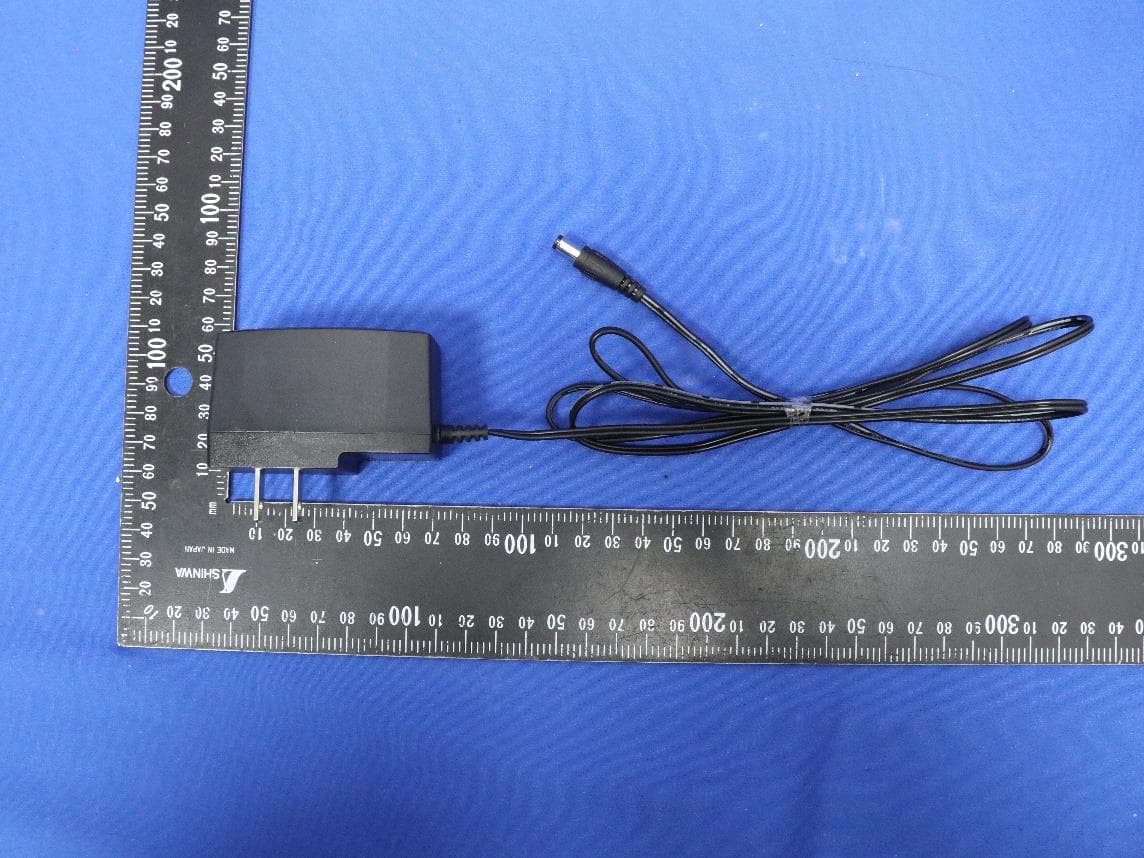
Click to zoom
Application Details
- Equipment Class
- NII - Unlicensed National Information Infrastructure TX
- Date of Grant
- May 29, 2026
- Application Purpose
- Original Equipment
- Equipment Note
- 5GHz 867Mbps Indoor/Outdoor Wireless Flex Bridge
- Frequency Range
- 5180.00000000 - 5240.00000000
- Company
- TP-Link Systems Inc.
- Country
- United States
Documents & Files
Document Text
Text extracted from the exhibit documents filed with the FCC. Open a document above to read the original.
Users Manual
Regulatory Compliance Flex Bridge 5 © 2026 TP-Link 1900002154 REV1.0.0 FCC Compliance Information Statement Product Name: 5GHz 867Mbps Indoor/Outdoor Wireless Flex Bridge Model Number: Flex Bridge 5 Component NameModel I.T.E. Power SupplyPOE5430G-M2 Responsible party: TP-Link Systems Inc. Address: 10 Mauchly, Irvine, CA 92618 Website: https://www.tp-link.com/us/ Tel: +1 626 333 0234 Fax: +1 909 527 6804 E-mail: [email protected] This equipment has been tested and found to comply with the limits for a Class B digital device, pursuant to part 15 of the FCC Rules. These limits are designed to provide reasonable protection against harmful interference in a residential installation. This equipment generates, uses and can radiate radio frequency energy and, if not installed and used in accordance with the instructions, may cause harmful interference to radio communications. However, there is no guarantee that interference will not occur in a particular installation. If this equipment does cause harmful interference to radio or television reception, which can be determined by turning the equipment off and on, the user is encouraged to try to correct the interference by one or more of the following measures: •Reorient or relocate the receiving antenna. •Increase the separation between the equipment and receiver. •Connect the equipment into an outlet on a circuit different from that to which the receiver is connected. •Consult the dealer or an experienced radio/ TV technician for help. This device complies with part 15 of the FCC Rules. Operation is subject to the following two conditions: 1) This device may not cause harmful interference. 2) This device must accept any interference received, including interference that may cause undesired operation. Any changes or modifications not expressly app roved by the party responsible for compliance could void the user’s authority to operate the equipment. Note: The manufacturer is not responsible for any radio or TV interference caused by unauthorized modifications to this equipment. Such modifications could void the user’s authority to operate the equipment. FCC RF Radiation Exposure Statement: This equipment complies with FCC RF radiation exposure limits set forth for an uncontrolled environment. This device and its antenna must not be co-located or operating in conjunction with any other antenna or transmitter. “To comply with FCC RF exposure compliance requirements, this grant is applicable to only Mobile Configurations. The antennas used for this transmitter must be installed to provide a separation distance of at least 43cm from all persons and must not be colocated or operating in conjunction with any other antenna or transmitter.” Product Name: I. T.E. Power Supply Model Number: POE5430G-M2 Responsible party: TP-Link Systems Inc. Address: 10 Mauchly, Irvine, CA 92618 Website: https://www.tp-link.com/us/ T el: +1 626 333 0234 Fax: +1 909 527 6804 E-mail: [email protected] This equipment has been tested and found to comply with the limits for a Class B digital device, pursuant to part 15 of the FCC Rules. These limits are designed to provide reasonable protection against harmful interference in a residential installation. This equipment generates, uses and can radiate radio frequency energy and, if not installed and used in accordance with the instructions, may cause harmful interference to radio communications. However, there is no guarantee that in terference will not occur in a particular installation. If this equipment does cause harmful interference to radio or television reception, which can be determined by turning the equipment off and on, the user is encouraged to try to correct the interference by one or more of the following measures: •Reorient or relocate the receiving antenna. • Increase the separation between the equipment and receiver. •Connect the equipment into an outlet on a circuit different from that to which the receiver is connected. •Consult the dealer or an experienced radio/ TV technician for help. This device complies with part 15 of the FCC Rules. Operation is subject to the following two conditions: 1) This device may not cause harmful interference. 2) This device must accept any interference received, including interference that may cause undesired operation. Any changes or modifications not expressly approved by the party responsible for compliance could void the user’s authority to operate the equipment. We, TP-Link Systems Inc., has determined that the equipment shown as above has been shown to comply with the applicable technical standards, FCC part 15. There is no unauthorized change is made in the equipment and the equipment is properly maintained and operated. Issue Date: 2026-03-04 CE Mark Warning OPERATING FREQUENCY (the maximum transmitted power) 5150MHz—5250MHz (23dBm) 5250MHz—5350MHz (23dBm) 5470MHz—5725MHz (30dBm) EU Declaration of Conformity TP-Link hereby declares that the Access Point is in compliance with the essential requirements and other relevant provisions of directives 2014/53/EU, 2009/125/EC, 2011/65/EU and (EU)2015/863. The original EU Declaration of Conformity may be found at https://www.tp-link.com/en/support/ c e /. RF Exposure Information This device meets the EU requirements (2014/53/EU Article 3.1a) on the limitation of exposure of the general public to electromagnetic fields by way of health protection. The device complies with RF specifications when the device used at 20cm from your body. National Restrictions Frequency band: 5150 - 5250 MHz: Indoor use: Inside buildings only. Installations and use inside road vehicles and train carriages are not permitted. Limited outdoor use: If used outdoors, equipment shall not be attached to a fixed installation or to the external body of road vehicles, a fixed infrastructure or a fixed outdoor antenna. Use by unmanned aircraft systems (UAS) is limited to within the 5170 - 5250 MHz band. Frequency band: 5250 - 5350 MHz: Indoor use: Inside b…
Text truncated - open the document above for the full version.
Users Manual
Indoor/Outdoor Wireless Flex Bridge © 2025 TP-Link 7100002629 REV1.0.1 Note: Flex Bridge 5 is used for demonstration. Images may differ from your actual product. Scan for Bridge AP Start Guide Quick Installation Guide Note: Accessories may vary by region and model. Package ContentsOpen the Cover Choose a grounding method according to site requirements: Method ①: PoE Adapter + Shielded CAT5e (or above) Cable with Ground Wire + Grounded 3-Wire Power Outlet Method ②: Grounding Terminal + Ground Wire Grounding Grounding Terminal Earth Ground 2 1 1 1 Grounded PoE Adapter Ground Wire Shielded CAT5e (or above) Cable with Ground Wire Grounded 3-Wire Power Outlet Power On Pairing 1. The default SSID on the product is only for device access and management. If you need an SSID to access the internet and service networks, refer to the Network Management section to set up the AP. 2. In a network without a DHCP Server, the Main AP will use the DHCP fallback IP address 192.168.0.254 and assign IP addresses to Client APs. Typical Topology Scenario 2: Wi-Fi ExtensionScenario 1: Remote Camera Monitoring NVR Main AP CamerasClient APs Main AP APsClientsClient APs Gateway/Router Client APsAPsClients 123 Toggle the Role switch to assign each AP’s role. Each group contains one Main AP and one or several Client APs. Toggle the Pairing Code switches to set each AP’s pairing code. The APs in the same group use the same pairing code, and different groups use different pairing codes. When a Client AP’s Signal LEDs turn solid, it is networked successfully. 1×1× 1×1× Mounting Kit 2×2× 1×1× Guide Option 1: Via Power Adapter Option 2: Via PoE Switch Option 3: Via Passive PoE Adapter Power Port Power Adapter PoE Switch LAN1(PoE IN) Passive PoE Adapter LAN1(PoE IN) 1×1×1×1× 4×4×2× M3.5*8 2×2× ST4*16 1× M3*8 For ground wire without an OT terminal 1× Main AP M C Client AP M C Client AP M C Main AP Client AP 0 1 0 1 0 1 0 1 0 1 0 1 0 1 0 1 Client AP 0 1 0 1 0 1 0 1 Main AP Client AP ≥ 3 Signal LEDs On Client AP ≥ 3 Signal LEDs On Loosen the attached screws and slide open the cover. Notes: 1. Normally, the wireless bridge setup completes within 2 minutes. If the connection is not established within 10 minutes, please check the following: • Ensure that the Pairing Code switches on the Client AP are set to the same code as the Main AP. • Adjust the alignment and orientation of the Client AP to ensure it is properly aimed at the Main AP and receiving sufficient signal strength. 2. The Main AP’s pairing window will time out 2 hours after the first Client AP connects to it. To start the pairing window again, refer to the user manual at https://support.omadanetworks.com/document/. RolePairing Code Main AP Client AP 1C111 0M000 LAN2(PoE OUT)LAN1(PoE IN)12V DCResetLAN3(PoE OUT) SSID: Omada_2.4GHz_XXXXXX Option 1: Standalone Mode Configure and manage APs through the Main AP. Network Management Option 2: Controller Mode Configure and manage APs (and other Omada devices) centrally with an Omada Controller. Scan for Standalone Start Guide Scan for Controller Start Guide More Configurations For more configurations, refer to the User Guides of the Omada Controller and Omada APs at: https://support.omadanetworks.com/document/ Omada App With the TP-Link Omada app, you can access and manage your Omada devices at a local site or remotely with a tap of your phone. OR Scan for OmadaOmada App Switch Gateway/Router On-Premises Controller Omada Central (Cloud-Based) Or Main AP Client APs Main APClient AP Main APClient AP SwitchGateway/Router Main AP Client APs Management Client TP-Link hereby declares that the Bridge AP is in compliance with the essential requirements and other relevant provisions of directives 2014/53/EU, 2009/125/EC, 2011/65/EU and (EU)2015/863. The original EU Declaration of Conformity may be found at https://www.tp-link.com/en/support/ce/. TP-Link hereby declares that the Bridge AP is in compliance with the essential requirements and other relevant provisions of the Radio Equipment Regulations 2017. The original UK Declaration of Conformity may be found at https://www.tp-link.com/support/ukca/ Safety Information • Keep the device away from fire or hot environments. DO NOT immerse in water or any other liquid. • Do not attempt to disassemble, repair, or modify the device. If you need service, please contact us. • Do not use the device where wireless devices are not allowed. • Do not use a damaged charger or USB cable to charge the device. • Do not use any other chargers than those recommended. • The adapter shall be installed near the equipment and shall be easily accessible. • The adapter should be used indoors where the ambient temperature is lower than or equal to 40 °C. • The socket-outlet shall be installed near the equipment and shall be easily accessible. • Plug the adapter into a wall outlet with an earthing connection through the power supply cord. • The PoE ports shall not be used to charge lithium batteries or devices supplied by lithium batteries. • Use only power supplies which are provided by manufacturer and in the original packing of this product. If you have any questions, please don't hesitate to contact us. • This equipment can be powered only by equipments that comply with Power Source Class 2 (PS2) or Limited Power Source (LPS) defined in the standard of IEC 62368-1. • Use only power supplies listed in the user instructions. Refer to the User Manual on the product support page. AT EE IS NOPLPTROSE SI SK UK(NI) ITLILTLULVMTNL ELESFIFRHR HUIE BEBGCHCYCZDEDK UK For AP Controller, go to the Devices page and select the desired AP to specify the channel. For web browser, go to Wireless > Wireless Settings to specify the channel. Attention: In EU member states, EFTA countries and Northern Ireland, the operation in the frequency range 5150MHz - 5350MHz is only permitted indoors. Attention: In Great Britain, the operation in the frequency range 5150MHz - 5350MHz is only permitted indoors. For details on the warranty…
Text truncated - open the document above for the full version.
External Photos
Report No.: R25S1033129-UE 1 of 12 External Photograph (1) EUT Photo (2) EUT Photo Report No.: R25S1033129-UE 2 of 12 (3) EUT Photo (4) EUT Photo Report No.: R25S1033129-UE 3 of 12 (5) EUT Photo (6) EUT Photo Report No.: R25S1033129-UE 4 of 12 (7) EUT Photo (8) EUT Photo Report No.: R25S1033129-UE 5 of 12 (9) EUT Photo (10) EUT Photo
Test Setup Photos
Report No.: R25S1033129-UT 1 of 4 RF Test Setup Photograph Description: Front View of Conducted Emissions Test Setup Description: Side View of Conducted Emissions Test Setup Report No.: R25S1033129-UT 2 of 4 Description: Radiated Spurious Emissions Test Setup for Below 30 MHz Description: Radiated Spurious Emissions Test Setup for Below 1 GHz Report No.: R25S1033129-UT 3 of 4 Description: Radiated Spurious Emissions Test Setup for Above 1 GHz (WZ-AC1) Description: Radiated Spurious Emissions Test Setup for Above 1 GHz (WZ-AC2) Report No.: R25S1033129-UT 4 of 4 Description: Radiated Spurious Emissions Test Setup for Above 18 GHz Description: Conducted Test Setup
Test Report
Report No.: R25S1033129-U202 54 of 118 802.11ac-VHT40 Power Spectral Density - Ant 1 Channel 38 (5190 MHz) Channel 46 (5230 MHz) Channel 151 (5755 MHz) Channel 159 (5795 MHz) Report No.: R25S1033129-U202 55 of 118 802.11ac-VHT80 Power Spectral Density - Ant 1 Channel 42 (5210 MHz) Channel 155 (5775 MHz) Report No.: R25S1033129-U202 56 of 118 A.6 Frequency Stability Test Result Test Site WZ-TR3 Test Engineer Molly Wu Test Date 2026-01-23 Test Mode 5180 MHz (Carrier Mode) Voltage (%) Power (VAC) Temp (°C) Frequency Tolerance (ppm) 0 minutes 2 minutes 5 minutes 10 minutes 100% 120 - 30 7.32 7.29 7.24 7.21 - 20 9.16 9.17 9.15 9.13 - 10 9.12 9.28 9.42 9.57 0 6.09 6.02 5.99 6.01 + 10 1.80 2.25 2.49 2.70 + 20 -2.50 -2.35 -2.22 -2.12 + 30 -4.19 -4.04 -3.89 -3.75 + 40 -7.97 -7.88 -7.80 -7.71 + 50 -7.68 -8.03 -8.12 -8.21 115% 138 + 20 -3.08 -3.59 -3.85 -4.08 85% 102 + 20 -4.32 -4.48 -4.60 -4.69 Note: Frequency Tolerance (ppm) = {[Measured Frequency (Hz) - Declared Frequency (Hz)] / Declared Frequency (Hz)} × 10 6 . Report No.: R25S1033129-U202 57 of 118 A.7 Radiated Spurious Emissions Test Result Test Site WZ-AC2 Test Engineer Dick Shen Test Date 2025-12-22 Test Mode 802.11a - Channel 36 Remark 1. Average measurement was not performed if peak level lower than average limit. 2. Other frequency was 20 dB below limit line within 1-18 GHz, there is not show in the report. Mark Frequency (MHz) Reading Level (dBμV) Factor (dB/m) Measure Level (dBμV/m) Limit (dBμV/m) Margin (dB) Detector Polarization * 9831.50 33.82 14.14 47.96 68.20 -20.24 Peak Horizontal 11511.10 31.24 18.11 49.35 74.00 -24.65 Peak Horizontal * 16726.70 30.96 22.32 53.28 68.20 -14.92 Peak Horizontal 18000.00 12.54 31.72 44.26 54.00 -9.74 Average Horizontal 18000.00 27.75 31.72 59.47 74.00 -14.53 Peak Horizontal 12218.30 31.40 18.31 49.71 74.00 -24.29 Peak Vertical * 14149.50 29.07 21.80 50.87 68.20 -17.33 Peak Vertical * 16901.80 27.57 22.63 50.20 68.20 -18.00 Peak Vertical 18000.00 12.39 31.72 44.11 54.00 -9.89 Average Vertical 18000.00 27.41 31.72 59.13 74.00 -14.87 Peak Vertical Note 1: “ * ” is not in restricted band Note 2: Measure Level (dBμV/m) = Reading Level (dBμV) + Factor (dB/m) Factor (dB/m) = Cable Loss (dB) + Antenna Factor (dB/m) - Pre_Amplifier Gain (dB) Report No.: R25S1033129-U202 58 of 118 Test Site WZ-AC2 Test Engineer Dick Shen Test Date 2025-12-26 Test Mode 802.11a - Channel 44 Remark 1. Average measurement was not performed if peak level lower than average limit. 2. Other frequency was 20 dB below limit line within 1-18 GHz, there is not show in the report. Mark Frequency (MHz) Reading Level (dBμV) Factor (dB/m) Measure Level (dBμV/m) Limit (dBμV/m) Margin (dB) Detector Polarization 11421.00 31.91 18.16 50.07 74.00 -23.93 Peak Horizontal * 14460.60 31.20 22.16 53.36 68.20 -14.84 Peak Horizontal * 17199.30 31.45 23.29 54.74 68.20 -13.46 Peak Horizontal 18000.00 12.80 31.72 44.52 54.00 -9.48 Average Horizontal 18000.00 29.09 31.72 60.81 74.00 -13.19 Peak Horizontal 11579.10 30.83 18.10 48.93 74.00 -25.07 Peak Vertical * 14186.90 31.44 22.15 53.59 68.20 -14.61 Peak Vertical * 17229.90 31.03 23.42 54.45 68.20 -13.75 Peak Vertical 18000.00 12.57 31.72 44.29 54.00 -9.71 Average Vertical 18000.00 27.96 31.72 59.68 74.00 -14.32 Peak Vertical Note 1: “ * ” is not in restricted band Note 2: Measure Level (dBμV/m) = Reading Level (dBμV) + Factor (dB/m) Factor (dB/m) = Cable Loss (dB) + Antenna Factor (dB/m) - Pre_Amplifier Gain (dB) Report No.: R25S1033129-U202 59 of 118 Test Site WZ-AC2 Test Engineer Dick Shen Test Date 2025-12-26 Test Mode 802.11a - Channel 48 Remark 1. Average measurement was not performed if peak level lower than average limit. 2. Other frequency was 20 dB below limit line within 1-18 GHz, there is not show in the report. Mark Frequency (MHz) Reading Level (dBμV) Factor (dB/m) Measure Level (dBμV/m) Limit (dBμV/m) Margin (dB) Detector Polarization * 10516.60 32.01 15.85 47.86 68.20 -20.34 Peak Horizontal 11538.30 31.10 18.04 49.14 74.00 -24.86 Peak Horizontal * 17326.80 31.00 23.85 54.85 68.20 -13.35 Peak Horizontal 18000.00 12.69 31.72 44.41 54.00 -9.59 Average Horizontal 18000.00 28.55 31.72 60.27 74.00 -13.73 Peak Horizontal * 10105.20 31.99 14.27 46.26 68.20 -21.94 Peak Vertical 11592.70 31.01 18.08 49.09 74.00 -24.91 Peak Vertical * 16891.60 29.89 22.58 52.47 68.20 -15.73 Peak Vertical 17853.80 14.61 29.82 44.43 54.00 -9.57 Average Vertical 17853.80 29.78 29.82 59.60 74.00 -14.40 Peak Vertical Note 1: “ * ” is not in restricted band Note 2: Measure Level (dBμV/m) = Reading Level (dBμV) + Factor (dB/m) Factor (dB/m) = Cable Loss (dB) + Antenna Factor (dB/m) - Pre_Amplifier Gain (dB) Report No.: R25S1033129-U202 60 of 118 Test Site WZ-AC2 Test Engineer Dick Shen Test Date 2025-12-26 Test Mode 802.11a - Channel 149 Remark 1. Average measurement was not performed if peak level lower than average limit. 2. Other frequency was 20 dB below limit line within 1-18 GHz, there is not show in the report. Mark Frequency (MHz) Reading Level (dBμV) Factor (dB/m) Measure Level (dBμV/m) Limit (dBμV/m) Margin (dB) Detector Polarization 7660.60 36.60 10.65 47.25 74.00 -26.75 Peak Horizontal * 9806.00 32.97 14.21 47.18 68.20 -21.02 Peak Horizontal * 17131.30 30.62 22.46 53.08 68.20 -15.12 Peak Horizontal 17991.50 13.84 30.44 44.28 54.00 -9.72 Average Horizontal 17991.50 30.07 30.44 60.51 74.00 -13.49 Peak Horizontal * 10142.60 32.74 14.40 47.14 68.20 -21.06 Peak Vertical 11424.40 30.96 18.17 49.13 74.00 -24.87 Peak Vertical * 17110.90 31.58 22.51 54.09 68.20 -14.11 Peak Vertical 17996.60 13.21 31.21 44.42 54.00 -9.58 Average Vertical 17996.60 29.55 31.21 60.76 74.00 -13.24 Peak Vertical Note 1: “ * ” is not in restricted band Note 2: Measure Level (dBμV/m) = Reading Level (dBμV) + Factor (dB/m) Factor (dB/m) = Cable Loss (dB) + Antenna Factor (dB/m) - Pre_Amplifier Gain (dB) Report No.: R25S1033129-U202 61 of 118 Test Site WZ-AC2 Test Engineer Dick Shen Test Date 2025-12-26 Test Mode 802.11a - Channel 157 Remark 1. Av…
Text truncated - open the document above for the full version.
Test Report
MRT Technology (Suzhou) Co., Ltd. Report No.: R25S1033129-U202 Phone: +86-512-66308358 Report Version: V01 Web: www.mrt-cert.com Issue Date: 2026-04-30 Template Version: 2.2 1 of 118 RF MEASUREMENT REPORT FCC ID: 2BH7FFLEXBRG5 Applicant: TP-Link Systems Inc. Product: 5GHz 867Mbps Indoor/Outdoor Wireless Flex Bridge Model No.: Flex Bridge 5 Brand Name: tp-link FCC Classification: Unlicensed National Information Infrastructure (NII) FCC Rule Part(s): Part 15 Subpart E (Section 15.407) Result: Complies Received Date: 2025-12-16 Test Date: 2025-12-22 ~ 2026-04-10 Reviewed By: Yuri Li Approved By: Robin Wu The test results relate only to the samples tested. This equipment has been shown to be capable of compliance with the applicable technical standards as indicated in the measurement report. Testing was performed in accordance with the applicable measurement procedures. The test results reported herein apply only to the specific item(s) tested. The test report shall not be reproduced except in full without the written approval of MRT Technology (Suzhou) Co., Ltd. Report No.: R25S1033129-U202 2 of 118 Revision History Report No. Version Description Issue Date Note R25S1033129-U202 V01 Initial Report 2026-04-30 Valid Report No.: R25S1033129-U202 3 of 118 CONTENTS Description Page 1. General Information ................................................................................................................................ 6 1.1. Applicant ..................................................................................................................................... 6 1.2. Manufacturer............................................................................................................................... 6 1.3. Testing Facility ............................................................................................................................ 6 1.4. Product Information .................................................................................................................... 7 1.5. Radio Specification under Test ................................................................................................... 7 1.6. Working Frequencies .................................................................................................................. 8 1.7. Antenna Details .......................................................................................................................... 8 2. Test Configuration ................................................................................................................................... 9 2.1. Test Mode ................................................................................................................................... 9 2.2. Test System Connection Diagram .............................................................................................. 9 2.3. Test Software .............................................................................................................................. 9 2.4. Applied Standards .................................................................................................................... 10 2.5. Test Environment Condition ...................................................................................................... 10 3. Antenna Requirements ......................................................................................................................... 11 4. Measuring Instrument ........................................................................................................................... 12 5. Decision Rules and Measurement Uncertainty .................................................................................. 13 5.1. Decision Rules .......................................................................................................................... 13 5.2. Measurement Uncertainty ........................................................................................................ 13 6. Test Result .............................................................................................................................................. 14 6.1. Summary .................................................................................................................................. 14 6.2. 26 dB & 99% Bandwidth Measurement .................................................................................... 15 6.2.1. Test Limit ................................................................................................................................... 15 6.2.2. Test Procedure ......................................................................................................................... 15 6.2.3. Test Setting ............................................................................................................................... 15 6.2.4. Test Setup ................................................................................................................................. 15 6.2.5. Test Result ................................................................................................................................ 16 6.3. 6 dB Bandwidth Measurement ................................................................................................. 17 6.3.1. Test Limit ................................................................................................................................... 17 6.3.2. Test Procedure ......................................................................................................................... 17 6.3.3. Test Setting ............................................................................................................................... 17 6.3.4. Test Setup ................................................................................................................................. 17 6.3.5. Test Result ..........…
Text truncated - open the document above for the full version.
Test Report
Product Model: Flex Bridge 5 Manufacturer: TP-Link Systems Inc. Test Date: 2025.11.10 Tested By: Shao Jinwei TP-Link Systems Inc. 10 Mauchly, Irvine, CA 92618 Index 1. Antenna Distribution ........................................................................................ 3 2. Electrical Characteristics ................................................................................ 3 Gain and Radiation Pattern ..................................................................................... 4 2.1 Measurement Procedure ......................................................................................... 4 2.2 Test Setup ............................................................................................................... 5 2.3 S Parameter Test Data ............................................................................................ 6 2.4 Antenna Gain .......................................................................................................... 7 2.4.1 Peak Gain ......................................................................................................................... 7 2.4.2 Horizontal plane Gain ....................................................................................................... 7 2.5 Antenna Radiation Pattern ....................................................................................... 7 Page 3 1. Antenna Distribution Flex Bridge 5 2. Electrical Characteristics Ant1 Frequency 5150~5895MHz Impedance 50Ohm Antenna Type Microstrip Antenna Gain 14.80dBi@5150~5250MHz 14.80dBi@5250~5350MHz 13.83dBi@5470~5725MHz 13.48dBi@5725~5895MHz Radiation pattern Directional P/N 3100000607 Ant2 Frequency 5150~5895MHz Impedance 50Ohm Antenna Type Microstrip Antenna Gain 15.95dBi@5150~5250MHz 15.95dBi@5250~5350MHz 15.28dBi@5470~5725MHz 14.84dBi@5725~5895MHz Radiation pattern Directional P/N 3100000607 Ant3 Frequency 2400~2500MHz Impedance 50Ohm Antenna Type IFA Antenna Gain 1.07dBi@2400~2500MHz Radiation pattern Omni-Directional P/N Flex Brideg 5_Ant3 Page 4 Gain and Radiation Pattern 2.1 Measurement Procedure This measurement experiment adopted an antenna near-field measurement system, and the diagram of the measurement system was shown in Figure 3-1. The excitation signal was generated by the Keysight E5071C (300kHz-20GHz). Under the control of the central computer, the probe rotated in the θ direction, and the EUT rotated in the φ direction with the turntable. The probe sampling frame received and collected signals in the near-field range of the EUT. The software system which was controlled by the central computer completed the processing, output and display of the test data. Figure 0-1 The test site was a full anechoic chamber with a size of 3.0m×3.1m×2.97m, which was built by GTS Rayzone2800. All six surfaces of the anechoic chamber were pasted with absorbing materials. And the chamber was calibrated by the authoritative third-party lab every year. The antenna anechoic chamber measurement system adopted a 13-probe multi-probe system. The probe antennas were evenly distributed on the spherical surface surrounding the EUT, and theirs operating frequency was 600MHz~8.5GHz. During the measurement, the probe antennas were rotated in the θ direction under the control of the probe holder to sample the near-field data at the θ angle. At the same time, the EUT rotated with the turntable in the φ direction to sample the near field data at the φ angle. The sampling accuracy was 15°. The system diagram was shown in Figure 3-2. From the sampling results, the EUT's near-field test data of θ component, φ component and total component could be obtained. Page 5 Figure 0-2 Before the measurement, calibrated the vector network analyzer, and then connected the input end of each antenna to the output end of the vector network analyzer, and evenly the antennas to be measured. Test Equipment listed below: Equipments Model Manufacturer S/N Cali. Interval Cali. Due Date Chamber Rayzone2800 GTS(General Test System) MY5347043 5 12months 2026/01/15 Vector Network Analyzer E5071C Keysight MY46315238 24months 2026/03/13 GTS MaxSign100 Software V2.1 GTS(General Test System) / / / 2.2 Test Setup The test setup was shown in Figure 3-3, 3-4: Figure 0-3 Page 6 Figure 0-4 2.3 S Parameter Test Data Ant1 Ant2 Ant3 Page 7 2.4 Antenna Gain 2.4.1 Peak Gain Frequency 2.45GHz 2400~2500MHz Ant3 MaxGain(dBi) 1.07 Ant3 Polarization/Φ (°)/θ(°) Theta/60/75 Max Gain(dBi) 1.07 Frequency 5.2GHz 5150~5250MHz 5.3GHz 5250~5350MHz 5.6GHz 5470~5725MHz 5.8GHz 5725~5895MHz Ant1 MaxGain(dBi) 14.80 14.80 13.83 13.48 Ant2 MaxGain(dBi) 15.95 15.95 15.28 14.84 Ant1 Polarization/Φ (°)/θ(°) Theta/90/90 Theta/90/90 Theta/90/90 Theta/90/90 Ant2 Polarization/Φ (°)/θ(°) Phi/90/90 Phi/90/90 Phi/90/90 Phi/90/90 Max Gain(dBi) 15.95 15.95 15.28 14.84 2.4.2 Horizontal plane Gain 2.4.2.1. 5150~5250MHz θ >30° Ant1 MaxGain(dBi) -2 Ant2 MaxGain(dBi) -2 Max Gain(dBi) -2 2.5 Antenna Radiation Pattern Ant1 Page 8…
Text truncated - open the document above for the full version.
Contact Information
Applicant
Sarah Wang
[email protected]Fax: 6263330234
Technical Contact
TP-Link Systems Inc.Sarah Wang
[email protected]Fax: 6263330234
10 Mauchly, Irvine, CA 92618 · Irvine, 92618 · United States
Test Firm
MRT Technology (Suzhou) Co., Ltd.Mr. Marlin Chen
Technical Specifications
| # | Rule Parts | Frequency Range | Power Output |
|---|---|---|---|
| 1 | 15E | 5.18 GHz - 5.24 GHz | 78.50 mW |
| 2 | 15E | 5.75 GHz - 5.83 GHz | 123.90 mW |