2BHBN-3DLaser level
Yangzhou Vikala Laser Technology Co., Ltd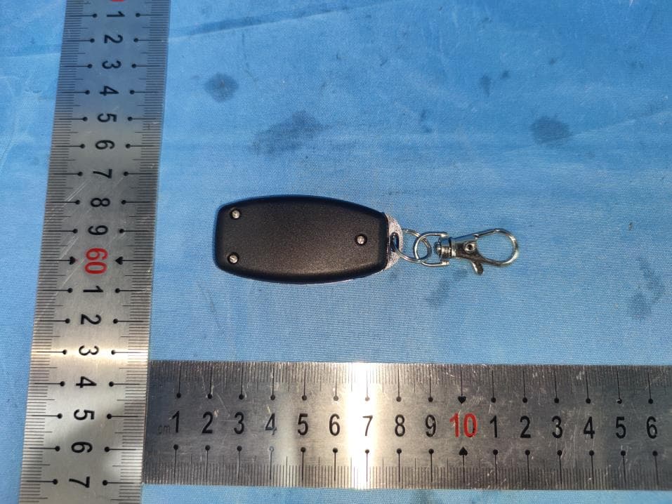
Click to zoom
Application Details
- Equipment Class
- DSC - Part 15 Security/Remote Control Transmitter
- Date of Grant
- Jul 26, 2024
- Application Purpose
- Original Equipment
- Date of Application
- Jul 26, 2024
- Equipment Note
- Laser level
- Frequency Range
- 433.92000000 - 433.92000000
- Country
- China
Documents & Files
Document Text
Text extracted from the exhibit documents filed with the FCC. Open a document above to read the original.
Users Manual
Product Introduction Manual Please be sure to read all safety clauses and operating instructions in this manual before using the product -1- VS5-3-F Laser Level PDF created with pdfFactory Pro trial version www.pdffactory.com Battery Indicator Brightness Adjustment\ Buzzer Off and On Button Vertical Button Modulation\ Burst Button Horizontal Button Control Panel 2 -2- Product Description Host Introduction 1 Horizontal Windows Mainframe Housing Vertical Windows Control Panel Battery Cover Locking Switch Main unit Base PDF created with pdfFactory Pro trial version www.pdffactory.com Other Accessories5 -3- Bracket Introduction 3 Remote Control Introduction 4 Move Forward and Backward L-Shaped Iron Plate Adjust Up and Down Rotate Left and Right Horizontal Control Button Modulation Control Button Vertical Control Button 2 3 4 Laser Target Card Plate 1 Battery Charger Bracket Accessory PDF created with pdfFactory Pro trial version www.pdffactory.com -4- Product Technical Specifications 6 Operation Method 7 Place the level on the ground or install it on a bracket fixed on the wall. Fix the instrument on the bracket and adjust the tail and side knobs on the bracket so that the instrument is flat against the wall. When this model is powered on, long press (2-3S) the O key on the key panel to enter the slash mode; long press (2-3S) the O key on the key panel again to exit the slash mode. Turn on the locking switch of the level, the machine starts to work, the horizontal outlet opens automatically, emits horizontal laser rays, and controls the vertical or horizontal line through V or H on the key board. Laser Safety Standards Laser Wavelength Automatic Leveling Range Automatic Leveling Time Horizontal Accuracy Vertical Accuracy Line Width Brightness Adjustment 3 Levels of Brightness Power Supply Operating Temperature Storage Temperature Remote Control Distance Base Thread Size Class II laser products Green light 515nm ±0.3mm/m ±0.3mm/m 2mm/5m 100%, 75%, 50% DC3.7V 5000mAh 1/4 inch 1 2 3 4 PDF created with pdfFactory Pro trial version www.pdffactory.com -5- Accuracy Check 8 When this model is powered on, the vertical and horizontal light of the instrument are the brightest (100%). Short press the B button to adjust the vertical and horizontal light brightness of the instrument (3 levels of brightness, 100%, 75%, 50%, cycle in sequence) button on the remote control to turn on or off the horizontal light of the instrument, press the V button on the remote control to control the vertical light of the instrument on or off, press the The OD button controls the switching of instrument modulation, strobe and normal states. Establish 4 points arbitrarily on the four walls as the original coordinates when the horizontal laser is projected. Establish 4 points arbitrarily on the four walls as the original coordinates when the horizontal laser is projected. Hang a plumb line on the wall. Place the instrument 5 meters from the wall. Horizontal line check Vertical line check 5 6 1 2 3 1 2 PDF created with pdfFactory Pro trial version www.pdffactory.com -6- Common Faults and Troubleshooting 9 Use the vertical laser line emitted by the instrument to align the plumb line to see if the distance between the two is greater than the error range, and then the plumb line, and check the distance between the two.is greater than the error range. The remaining 1 laser inspection is the same as step 3. 3 4 The switch is turned to the "ON" position, but the laser line does not light up. Laser line flashes Instrument out of operating range Adjust the instrument to a roughly level state There is dust on the surface of the light outlet glass The laser line become thicker or blurry Clean with soft cloth dampened in water 1. Charge the lithium battery 2. Make sure the operating temperature of the instrument is between 1. Low battery power 2. The instrument exceeds the operating temperature range The switch is turned to the "ON" position, but the laser line does not light up. Laser line visibility deteriorates 1. Leave it for a period of time to make the temperature of the instrument consistent with the environment. 2. Send for repair 1. The ambient temperature of the instrument changes suddenly 2. The instrument has been subject to strong impact or drop. 1. The ambient light is too bright 2. Low battery power 1. Reduce ambient light brightness 2. Charge the lithium battery Phenomenon Cause Analysis Solutions PDF created with pdfFactory Pro trial version www.pdffactory.com -7- Operation Precautions 10 Security Terms 11 The lithium battery wall mounter has only a weak power when it leaves the factory. Please charge it before use. Before each use, self-check the accuracy of the instrument according to the instructions in the operation manual, and calibrate the accuracy of the instrument regularly. Avoid heavy impact or vibration, and lock the locking switch when not in use. Do not use organic solutions to wipe the surface of the instrument. 1 2 Do not attempt to change the performance of the laser in any way, as this may cause dangerous laser exposure. This product is harmless to the human body, but do not look directly at the laser. Class II laser products. Turn on the laser only when using the instrument. 1 2 3 3 4 Avoid exposing the instrument to sunlight. 5 When the instrument is not used for a long time, the battery should be removed. 6 The instrument should be stored in a dry and ventilated environment. 7 PDF created with pdfFactory Pro trial version www.pdffactory.com FCC Warning This device complies with part 15 of the FCC Rules. Operation is subject to the following two conditions: (1) This device may not cause harmful interference, and (2) this device must accept any interference received, including interference that may cause undesired operation. Any Changes or modifications not expressly approved by the party responsible for compliance could void the user's authority to operate the equipment. Note: This equipment has been t…
Text truncated - open the document above for the full version.
Attestation Statements
- Yangzhou Vikala Laser Technology Co., Ltd - Federal Communications Commission Authorization and Evaluation Division Equipment Authorization Branch 7435 Oakland Mills Road Columbia, MD 21046 7/3/2024 U.S. Agent Designation Yangzhou Vikala Laser Technology Co., Ltd acknowledges their consent for the following contact located in the United States to act as their agent for service of process for the equipment for which authorization is sought (FCC ID: 2BHBN-3D): Name and company of U.S. agent: UUX GROUP INC Physical U.S. address of agent: 36 South 18th Avenue, Suite A Brighton, CO USA 80601 FRN of U.S. agent: 0033701590 Email address of U.S. agent: [email protected] UUX GROUP INC acknowledges their obligation to accept service of process on behalf of Yangzhou Vikala Laser Technology Co., Ltd. Yangzhou Vikala Laser Technology Co., Ltd with the FRN 0035617778 accepts its obligation to maintain an agent for service of process in the United States for no less than one year after either the grantee has permanently terminated all marketing and importation of the applicable equipment within the U.S., or the conclusion of any Commission-related administrative or judicial proceeding involving the equipment, whichever is later. By signing this form, we confirm the above and that we are aware of the application requirements listed under § 2.911(d)(7). The information provided in this letter is based on the referenced rule parts of Title 47 of the CFR as well as KDB 986446 D01. An expiration date for this letter does not exist. In case the U.S. agent changes, the grantee is obligated to notify the FCC within 30 days via the granting TCB. Sincerely, Signature Ding Zhaofei ManagerYangzhou Vikala Laser Technology Co., Ltd Signature Jack Fu Manager UUX GROUP INC 48_[model] US_Agent_2.911(d)(7) - U, V05
External Photos
Page 1 of 4 FCC ID:2BHBN-3D Guangdong Asia Hongke Test Technology Limited B1/F, Building 11, Junfeng Industrial Park, Chongqing Road, Heping Community, Fuhai Street, Bao'an District, Shenzhen, Guangdong, China. EUT Constructional Details External EUT Photo Photo 1 Photo 2 Page 2 of 4 FCC ID:2BHBN-3D Guangdong Asia Hongke Test Technology Limited B1/F, Building 11, Junfeng Industrial Park, Chongqing Road, Heping Community, Fuhai Street, Bao'an District, Shenzhen, Guangdong, China. Photo 3 Photo 4 Page 3 of 4 FCC ID:2BHBN-3D Guangdong Asia Hongke Test Technology Limited B1/F, Building 11, Junfeng Industrial Park, Chongqing Road, Heping Community, Fuhai Street, Bao'an District, Shenzhen, Guangdong, China. Photo 5 Photo 6 Page 4 of 4 FCC ID:2BHBN-3D Guangdong Asia Hongke Test Technology Limited B1/F, Building 11, Junfeng Industrial Park, Chongqing Road, Heping Community, Fuhai Street, Bao'an District, Shenzhen, Guangdong, China. Photo 7 ---The End---
ID Label/Location Info
Label Size: L15mm *W12mm 1. The label is silk-screen on the sample Laser level Model Name: 3D FCC ID: 2BHBN-3D L W
Internal Photos
Page 1 of 6 FCC ID:2BHBN-3D Guangdong Asia Hongke Test Technology Limited B1/F, Building 11, Junfeng Industrial Park, Chongqing Road, Heping Community, Fuhai Street, Bao'an District, Shenzhen, Guangdong, China. EUT Constructional Details Internal EUT Photo Photo 1 Photo 2 Page 2 of 6 FCC ID:2BHBN-3D Guangdong Asia Hongke Test Technology Limited B1/F, Building 11, Junfeng Industrial Park, Chongqing Road, Heping Community, Fuhai Street, Bao'an District, Shenzhen, Guangdong, China. Photo 3 Photo 4 Page 3 of 6 FCC ID:2BHBN-3D Guangdong Asia Hongke Test Technology Limited B1/F, Building 11, Junfeng Industrial Park, Chongqing Road, Heping Community, Fuhai Street, Bao'an District, Shenzhen, Guangdong, China. Photo 5 Photo 6 Page 4 of 6 FCC ID:2BHBN-3D Guangdong Asia Hongke Test Technology Limited B1/F, Building 11, Junfeng Industrial Park, Chongqing Road, Heping Community, Fuhai Street, Bao'an District, Shenzhen, Guangdong, China. Photo 7 Photo 8 Page 5 of 6 FCC ID:2BHBN-3D Guangdong Asia Hongke Test Technology Limited B1/F, Building 11, Junfeng Industrial Park, Chongqing Road, Heping Community, Fuhai Street, Bao'an District, Shenzhen, Guangdong, China. Photo 9 Photo 10 Antenna Page 6 of 6 FCC ID:2BHBN-3D Guangdong Asia Hongke Test Technology Limited B1/F, Building 11, Junfeng Industrial Park, Chongqing Road, Heping Community, Fuhai Street, Bao'an District, Shenzhen, Guangdong, China. Photo 11 ------End------
RF Exposure Info
RF Exposure evaluation FCC ID: 2BHBN-3D Applicable Standard According to §1.1307(b)(1), systems operating under the provisions of this section shall be operated in a manner that ensures that the public is not exposed to radio frequency energy level in excess of the Commission’s guidelines. According to §1.1310 and §2.1093 RF exposure requirement KDB447498 v06: Mobile and Portable Devices RF Exposure Procedures and Equipment Authorization Policies 1.1. Requirement According to KDB447498 D01 General RF Exposure Guidance v06 Section 4.3.1 Standalone SAR test exclusion considerations: “Unless specifically required by the published RF exposure KDB procedures, standalone 1-g head or body and 10-g extremity SAR evaluation for general population exposure conditions, by measurement or numerical simulation, is not required when the corresponding SAR Test Exclusion Threshold condition, listed below, is satisfied. These test exclusion conditions are based on source-based time-averaged maximum conducted output power of the RF channel requiring evaluation, adjusted for tune-up tolerance, and the minimum test separation distance required for the exposure conditions.22 The minimum test separation distance is determined by the smallest distance from the antenna and radiating structures or outer surface of the device, according to the host form factor, exposure conditions and platform requirements, to any part of the body or extremity of a user or bystander (see 5) of section 4.1). To qualify for SAR test exclusion, the test separation distances applied must be fully explained and justified by the operating configurations and exposure conditions of the transmitter and applicable host platform requirements, typically in the SAR measurement or SAR analysis report, according to the required published RF exposure KDB procedures. When no other RF exposure testing or reporting is required, a statement of justification and compliance must be included in the equipment approval, in lieu of the SAR report, to qualify for the SAR test exclusion. When required, the device specific conditions described in the other published RF exposure KDB procedures must be satisfied before applying these SAR test exclusion provisions; for example, handheld PTT two-way radios, handsets, laptops & tablets etc.23 “ [(max. power of channel, including tune-up tolerance, mW)/ (min. test separation distance, mm)] · [√f (GHz)] ≤ 3.0 for 1-g SAR and ≤ 7.5 for 10-g extremity SAR, where: • f (GHz) is the RF channel transmit frequency in GHz • Power and distance are rounded to the nearest mW and mm before calculation • The result is rounded to one decimal place for comparison • 3.0 and 7.5 are referred to as the numeric thresholds in the step 2 below The test exclusions are applicable only when the minimum test separation distance is ≤ 50 mm and for transmission frequencies between 100 MHz and 6 GHz. When the minimum test separation distance is < 5 mm, a distance of 5 mm according to 5) in section 4.1 is applied to determine SAR test exclusion. Manufacturing Tolerance 433.92 MHz Frequency (MHz) OOK 433.92 Result (dBμV/m) 81.39 Result (dBm) -13.81 Target (dBm) -13 Tolerance ± (dB) 1.0 Note: dBm = dBμV/m – 95.2(at 3m) 2. E v a l u a t i o n R e s u l t Standalone Antenna 1 Band/Mode f (GHz) Antenna Distance (mm) RF output power including tune up SAR Test Exclusion Threshold SAR Test Exclusion Estimated SAR dBm mW SRD 0.43392 5 -12 0.06 0.008< 3 Yes / Remark: When the minimum test separation distance is < 5 mm, a distance of 5 mm according to f) in section 4.1 is applied to determine SAR test exclusion. 3. C o n c l u s i o n The measurement results comply with the FCC Limit per 47 CFR 2.1093 for the uncontrolled RF Exposure and SAR Exclusion Threshold per KDB 447498 v06, No SAR is required. .....................End.........................
Test Report
Antenna gain: 0dBi 12mm
Test Report
Page 1 of 29 Report No.: AITSZ24052908FW1 Guangdong Asia Hongke Test Technology Limited B1/F, Building 11, Junfeng Industrial Park, Chongqing Road, Heping Community, Fuhai Street, Bao'an District, Shenzhen, Guangdong, China. Test Report Client Information: Applicant: Yangzhou Vikala Laser Technology Co., Ltd Applicant add.: 1-, No. 9 Yangzijiang South Road, Yangzhou,Jiangsu, China Product Information: Product Name: Laser level Model No.: 3D Brand Name: N/A Test samples.: AITSZ24052908-1 FCC ID: 2BHBN-3D Standards: FCC 47 CFR PART 15 SUBPART C 15.231 Prepared By: Guangdong Asia Hongke Test Technology Limited B1/F, Building 11, Junfeng Industrial Park, Chongqing Road, Heping Community, Fuhai Street, Bao'an District, Shenzhen, Guangdong, China Date of Receipt: May 29,2024 Date of Test: May 29,2024~ July 22 2024 Date of Issue: July 22 2024 Test Result: Pass This device described above has been tested by Dongguan Yaxu (AiT) Technology Limited, and the test results show that the equipment under test (EUT) is in compliance with the FCC requirements. And it is applicable only to the tested sample identified in the report. This report shall not be reproduced except in full, without the written approval of Dongguan Yaxu (AiT) Technology Limited. Reviewed by: Approved by: Leon.yi Sean She Page 2 of 29 Report No.: AITSZ24052908FW1 Guangdong Asia Hongke Test Technology Limited B1/F, Building 11, Junfeng Industrial Park, Chongqing Road, Heping Community, Fuhai Street, Bao'an District, Shenzhen, Guangdong, China. 1 Contents Page COVER PAGE 1 CONTENTS 2 2 TEST SUMMARY 4 2.1 STATEMENT OF THE MEASUREMENT UNCERTAINTY 4 2.2 MEASUREMENT UNCERTAINTY 4 3 TEST FACILITY 5 3.1 DEVIATION FROM STANDARD 5 3.2 ABNORMALITIES FROM STANDARD CONDITIONS 5 3.3 TEST LOCATION 5 4 GENERAL INFORMATION 6 4.1 GENERAL DESCRIPTION OF EUT 6 5 DESCRIPTION OF TEST CONDITIONS 8 5.1 E.U.T. OPERATION 8 5.2 EUT PERIPHERAL LIST 9 5.3 TEST PERIPHERAL LIST 9 6 EQUIPMENTS LIST FOR ALL TEST ITEMS 10 7 TEST RESULT 11 7.1 ANTENNA REQUIREMENT 11 7.2 TRANSMIT TIME 12 7.2.1 Applied procedures / Limit 12 7.2.2 Test procedure 12 7.2.3 Deviation from standard 12 7.2.4 Test setup 12 7.2.5 Test results 13 7.3 FIELD STRENGTH OF FUNDAMENTAL& FIELD STRENGTH OF UNWANTED EMISSIONS 14 7.3.1 Test procedure 18 7.4 OCCUPIED BANDWIDTH & BAND EDGE 25 7.5 CONDUCTED EMISSIONS AT MAINS TERMINALS 150 KHZ TO 30 MHZ 27 7.5.1 Test Result 28 8 PHOTOGRAPHS 29 8.1 RADIATED EMISSION TEST SETUP 29 Page 3 of 29 Report No.: AITSZ24052908FW1 Guangdong Asia Hongke Test Technology Limited B1/F, Building 11, Junfeng Industrial Park, Chongqing Road, Heping Community, Fuhai Street, Bao'an District, Shenzhen, Guangdong, China. Revision History Revision Issue Date Revisions Revised By 000 July 22 2024 Initial Issue Sean She Page 4 of 29 Report No.: AITSZ24052908FW1 Guangdong Asia Hongke Test Technology Limited B1/F, Building 11, Junfeng Industrial Park, Chongqing Road, Heping Community, Fuhai Street, Bao'an District, Shenzhen, Guangdong, China. 2 Test Summary FCC Rule Description of Test Result Section 15.203 RSS-Gen section 6.8 Antenna Requirement Pass Section 15.207(a) RSS-Gen clause 8.8 Conduction Emissions N/A Section 15.209,15.231(b) RSS-210 A.1.2 Radiated Emissions Pass Section 15.231(c) RSS-Gen clause 6.7 &RSS-210 A.1.3 Occupied Bandwidth Pass Section 15.231(a) RSS 210 Issue 10 A.1.1(a) Transmit time Pass Note 1. Test according to ANSI C63.10:2013 and RSS-Gen. 2. The measurement uncertainty is not included in the test result. 3. Test results in other test report (RF Exposure Evaluation Report) 2.1 Statement of the Measurement Uncertainty The data and results referenced in this document are true and accurate. The reader is cautioned that there may be errors within the calibration limits of the equipment and facilities. The measurement uncertainty was calculated for all measurements listed in this test report acc. To CISPR 16 – 4 “Specification for radio disturbance and immunity measuring apparatus and methods – Part 4: Uncertainty in EMC Measurements” and is documented in the AiT quality system acc. To DIN EN ISO/IEC 17025. Furthermore, component and process variability of devices similar to that tested may result in additional deviation. The manufacturer has the sole responsibility of continued compliance of the device. 2.2 Measurement Uncertainty Test Item Frequency Range Measurement Uncertainty Notes Radiated Emission 0.009MHz-30MHz 3.10dB (1) Radiated Emission 30MHz-1GHz 3.75dB (1) Radiated Emission 1GHz-18GHz 3.88dB (1) Radiated Emission 18GHz-40GHz 3.88dB (1) AC Power Line Conducted Emission 0.15MHz ~ 30MHz 1.20dB (1) Note (1): The measurement uncertainty is for coverage factor of k=2 and a level of confidence of 95%. Page 5 of 29 Report No.: AITSZ24052908FW1 Guangdong Asia Hongke Test Technology Limited B1/F, Building 11, Junfeng Industrial Park, Chongqing Road, Heping Community, Fuhai Street, Bao'an District, Shenzhen, Guangdong, China. 3 Test Facility The test facility is recognized, certified or accredited by the following organizations: FCC-Registration No.: 251906 Designation Number: CN1376 Guangdong Asia Hongke Test Technology Limited has been registered and fully described in a report filed with the (FCC) Federal Communications Commission. The acceptance letter from the FCC is maintained in our files. IC —Registration No.: 31737 CAB identifier: CN0165 The 3m Semi-anechoic chamber of Guangdong Asia Hongke Test Technology Limited has been registered by Certification and Engineering Bureau of Industry Canada for radio equipment testing with Registration No.: 31737 A2LA-Lab Cert. No.: 7133.01 Guangdong Asia Hongke Test Technology Limited has been accredited by A2LA for technical competence in the field of electrical testing, and proved to be in compliance with ISO/IEC 17025: 2017 General Requirements for the Competence of Testing and Calibration Laboratories and any additional program requirements in the identified field of testing. 3.1 Deviation from standard None 3.2…
Text truncated - open the document above for the full version.
Test Setup Photos
Page 1 of 1 FCC ID:2BHBN-3D Guangdong Asia Hongke Test Technology Limited B1/F, Building 11, Junfeng Industrial Park, Chongqing Road, Heping Community, Fuhai Street, Bao'an District, Shenzhen, Guangdong, China. Test Setup Photo Radiated Emission ------End------
Contact Information
Applicant
Ding Zhaofei
Test Firm
Guangdong Asia Hongke Test Technology LimitedDarren Ding
[email protected]185656258618
Technical Specifications
| # | Rule Parts | Frequency Range | Power Output |
|---|---|---|---|
| 1 | 15.231 | 433.92 MHz - 433.92 MHz | - |