2BHHL-NQTXNoQ Transmitter
JTECH Global Enterprises Inc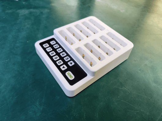
Click to zoom
Application Details
- Equipment Class
- TNB - Licensed Non-Broadcast Station Transmitter
- Date of Grant
- Aug 04, 2024
- Application Purpose
- Original Equipment
- Date of Application
- Aug 04, 2024
- Equipment Note
- NoQ Transmitter
- Frequency Range
- 450.02500000 - 469.97500000
- Company
- JTECH Global Enterprises Inc
- Country
- United States
Documents & Files
Document Text
Text extracted from the exhibit documents filed with the FCC. Open a document above to read the original.
Attestation Statements
Rev 1/26/2023 JTECH Global Enterprises Inc 1965 Evergreen Blvd, Ste 300, Georgia, Duluth, GA 30096, United States Tel: +1-800-321-6221 / Fax: +1-700-682-3459 Federal Communications Commission Authorization and Evaluation Division 7435 Oakland Mills Road Columbia, MD 21046 USA Date: June 25, 2024 Ref: Attestation Statements Part 2.911(d)(7) Filing FCC ID : 2BHHL-NQTX Applicant FRN: 0035666205 JTECH Global Enterprises Inc (“the applicant”) certifies that, as of the date of the filing of the application, we designate ourselves as the U.S. agent for service of process. Designated U.S. Agent Information: FRN: 0035666205 Name: JTECH Global Enterprises Inc Address: 1965 Evergreen Blvd, Ste 300, Georgia, Duluth, GA 30096, United States Contact Person: Salvatore Veni Tel.: +1-800-321-6221 Email: [email protected] Sincerely Yours, Salvatore Veni / Vice president JTECH Global Enterprises Inc
Attestation Statements
Rev 1/26/2023 JTECH Global Enterprises Inc 1965 Evergreen Blvd, Ste 300, Georgia, Duluth, GA 30096, United States Tel: +82-800-321-6221 / Fax: +82-700-682-3459 Federal Communications Commission Authorization and Evaluation Division 7435 Oakland Mills Road Columbia, MD 21046 USA Date: June 25, 2024 Ref: Attestation Statements Part 2.911(d)(5)(i) Filing FCC ID: 2BHHL-NQTX JTECH Global Enterprises Inc(“the applicant”) certifies that the equipment for which authorization is soughtis not“covered” equipment prohibited from receiving an equipment authorization pursuant to section 2.903 of the FCC rules. Sincerely, Salvatore Veni / Vice president JTECH Global Enterprises Inc Rev 1/26/2023 JTECH Global Enterprises Inc 1965 Evergreen Blvd, Ste 300, Georgia, Duluth, GA 30096, United States Tel: +82-800-321-6221 / Fax: +82-700-682-3459 Federal Communications Commission Authorization and Evaluation Division 7435 Oakland Mills Road Columbia, MD 21046 USA Date: June 25, 2024 Ref: Attestation Statements Part 2.911(d)(5)(ii) Filing FCC ID: 2BHHL-NQTX JTECH Global Enterprises Inc(“the applicant”) certifies that, as of the date of the filing of the application, the applicantis notidentified on the Covered List (as a specifically named entity or any of its subsidiaries or affiliates) as an entity producing “covered” equipment. Sincerely, Salvatore Veni / Vice president JTECH Global Enterprises Inc
Attestation Statements
Date: July 11, 2024 Federal Communications Commission Authorization and Evaluation Division 7435 Oakland Mills Road Columbia, MD 21046 SUBJECT: FCC ID: 2BHHL-NQTX Justification Letter for contiguous frequency range 450 ~ 470 MHz To Whom It May Concern: Being the Applicant for the captioned project, JTECH Global Enterprises Inc is requesting to list the frequencies 450 ~ 470 MHz under FCC Rules Part 90 on the FCC Grant. We attest that the device will be programmed by the manufacturer only for the frequencies authorized by Part 90, as listed in the table below, and the operator cannot program the transmit frequencies using the normally accessible external controls. Frequency Range(MHz)Rule PartGrant Notes 450 ~ 45490EF 454 ~ 45622,80,74EF 456 ~ 462.537590EF 462.5375 ~ 462.737595EF 462.7375 ~ 467.537590EF 467.5375 ~ 467.733595EF 467.7375 ~ 47090EF Salvatore Veni / Vice president JTECH Global Enterprises Inc
Cover Letter(s)
JTECH Global Enterprises Inc 1965 Evergreen Blvd, Ste 300, Georgia, Duluth, GA 30096, United States Tel: +82-800-321-6221 / Fax: +82-700-682-3459 Date: June 25, 2024 Federal Communications Commission Authorization and Evaluation Division Chief, Certification and Engineering Bureau Industry Canada 1241 Clyde Avenue Ottawa, Ontario Canada K2C 1Y3 Confidentiality Request regarding application for certification of FCC ID : 2BHHL-NQTX IC number : 32791-NQTX Pursuant to Sections 0.457 and 0.459 of the Commission’s Rules and IC regulation, we hereby request confidential treatment of information accompanying this application as outlined below: PERMANENT Exhibit TypeFile Name Part ListPart List.pdf Schematics Diagram(s)Schematic.pdf Operation descriptionOperation description.pdf Block diagramBlock diagram.pdf Tune up ProdedureTune up Prodedure.pdf And the above materials contain trade secrets and proprietary information not customarily released to the public. The public disclosure of these materials may be harmful to the applicant and provide unjustified benefits to its competitors. The applicant understands that pursuant to Section 0.457 of the Rules, disclosure of this application and all accompanying documentation will not be made before the date of the Grant for this application. Sincerely, Salvatore Veni / Vice president JTECH Global Enterprises Inc
Cover Letter(s)
JTECH Global Enterprises Inc 1965 Evergreen Blvd, Ste 300, Georgia, Duluth, GA 30096, United States Tel: +82-800-321-6221 / Fax: +82-700-682-3459 Date: June 25, 2024 Federal Communications Commission 7435 Oakland Mills Road Columbia MD 21046 Chief, Certification and Engineering Bureau Industry Canada 1241 Clyde Avenue Ottawa, Ontario Canada K2C 1Y3 FCC ID : 2BHHL-NQTX IC number : 32791-NQTX To whom it may concern: I, the undersigned, hereby authorize Young-Jin, Lee of KES Co., Ltd. and hereafter referred to as KES Co., Ltd., to act on our behalf in all manners relating to application for equipment authorization, including signing of all documents relating to these matters. Any and all acts carried out by Young-Jin, Lee of KES Co., Ltd. on our behalf shall have the same effect as acts of our own. I, the undersigned, hereby certify that we are not subject to a denial of federal benefits, that includes FCC benefits, pursuant to Section 5301 of the Anti-Drug Abuse Act of 1988, 21 U.S.C. 853(a). In authorizing KES Co., Ltd. as our agent, we still recognize that we are responsible to: a)comply with the relevant provisions of the certification program; b)make all necessary arrangements for the conduct of the evaluation, including provision for examining documentation and access to all areas, records (including internal audit reports) and personnel for the purposes of evaluation (e.g. testing, inspection, assessment, surveillance, reassessment) and resolution of complaints; c)make claims regarding certification only in respect of the scope for which certification has been granted; d)do not use our product certification in such a manner as to bring the Certification Division into disrepute and not make any statement regarding our product certification which the Certification Division may consider misleading or unauthorized; JTECH Global Enterprises Inc 1965 Evergreen Blvd, Ste 300, Georgia, Duluth, GA 30096, United States Tel: +82-800-321-6221 / Fax: +82-700-682-3459 e)upon suspension or cancellation of certification, discontinue use of all advertising matter that contains any reference thereto and return any certification documents as required by the Certification Division; f)use certification only to indicate the products are certified as being in conformity with specified standards; g)endeavor to ensure that no certificate or report nor any part thereof is used in a misleading manner; h)ensure that any reference to our product certification in communication media such as documents, brochures or advertising, complies with the requirements of the Certification Division; i)keep a record of all complaints made known to the us relating to the product’s compliance with requirements of the relevant standard and to make these records available to the Certification Division when requested; j)take appropriate action with respect to such complaints and any deficiencies found in products or services that affect compliance with the requirements for certification; k)document the actions taken. This authorization is valid until further written notice from the applicant. Sincerely Yours, Salvatore Veni / Vice president JTECH Global Enterprises Inc REMARK: 1.This authorization letter will be sent along with your application when filing with the Certification Division. 2.Please follow the format and type it on company letterhead and send original to us. 3.Authorized signature must be in agreement with grantee code contact in FCC database.
External Photos
FCC ID : 2BHHL-NQTX IC number : 32791-NQTX Page 1 of 2 External photos FCC ID : 2BHHL-NQTX IC number : 32791-NQTX Page 2 of 2
ID Label/Location Info
FCC ID : 2BHHL-NQTX IC number : 32791-NQTX Page 1 of 1 Label Location
Internal Photos
FCC ID : 2BHHL-NQTX IC number : 32791-NQTX Page 1 of 1 Internal photos Antenna
RF Exposure Info
FCC ID : 2BHHL-NQTXPage 1 of 1 RF exposure FCC ID : 2BHHL-NQTX According to FCC part 1.1310 : The criteria listed in the following table shall be used to evaluate the environment impact of human exposure to radio frequency (RF) radiation as specified in § 1.1307(b) Limits for Maximum Permissible Exposure (MPE) f= frequency in㎒ Friis transmission formula: Pd = (Pout×G)/(4×pi×R 2 ) Where, Pd = power density in㎽/㎠ Pout = output power to antenna in㎽ G = gain of antenna in linear scale Pi = 3.1416 R = distance between observation point and center of the radiator in cm Pd the limit of MPE, 1㎽/㎠. If we know the maximum gain of the antenna and the total power input to the antenna, through the calculation, we will know the distance where the MPE limit is reached. Results Mode Frequency (㎒) Maxmimum Average output power (㏈m) Antenna gain (㏈i) Power density at 20㎝(㎽/㎠) Limit (㎽/㎠) TX 450.025㎒ 21.00-18.550.000 350.30 457.575㎒ 21.00-18.550.000 350.30 469.975㎒ 21.00-18.550.000 350.31 Frequency range (㎒) Electric field strength(V/m) Magnetic field strength (A/m) Power density (㎽/㎠) Average time (A) Limits for Occupational / Control Exposures 300 – 1 500----f/3006 1 500 - 100000----56 (B) Limits for General Population / Uncontrol Exposures 300 – 1 500----f/15006 1 500 – 100 000----130
Test Report
Report No. : KES-RF240328-R1 Page 14 / 35 KES-QP16-F01(00-23-01-01) KES Co., Ltd. The authenticity of this test report can be found on the verification page of our website (www.kes.co.kr). 3.3 Emission mask Test setup EUT Attenuator Spectrum analyzer Test procedure 1. The transmitter output was connected to the spectrum analyzer through an attenuator 2. Use the following spectrum analyzer setting Span = 120 ㎑ RBW = 100 ㎐ VBW = 100 ㎐ (≥ RBW) Sweep = auto Detector function = peak Trace = max hold 3. Mark the peak frequency with maximum peak power as the center of the display of the spectrum analyzer. 4. Record the power spectrum analyzer and compare to the mask. Limit According to FCC part 90.210(d) Emission Mask D – 12.5 ㎑ channel bandwidth equipment. For transmitters designed to operate with a 12.5 ㎑ channel bandwidth, any emission must be attenuated below the power(P) of the highest emission contained within the authorized bandwidth as follows: (1) On any frequency from the center of the authorized bandwidth f 0 to 5.625 ㎑ removed from f 0 : Zero ㏈. (2) On any frequency removed from the center of the authorized bandwidth by a displacement frequency (f d in ㎑) of more than 5.625 ㎑, but no more than 12.5 ㎑: At least 7.27 (f d -2.88 ㎑) ㏈. (3) On any frequency removed from the center of the authorized bandwidth by a displacement frequency (f d in ㎑) of more than 12.5 ㎑: At least 50 + 10log(P) ㏈ or 70 ㏈, whichever is the lesser attenuation. RSS-119 5.8.3 The power of any emission shall be attenuated below the transmitter output power P(㏈W) as specified in Table 7. Table 7 – Emission Mask D Displacement Frequency, f d (㎑) Minimum Attenuation (㏈) Resolution Bandwidth (㎐) 5.625 < f d ≤ 12.5 7.27 (f d -2.88) Specified in Section 4.2.2 f d > 12.5 Whichever is the lesser: 70 or 50 + 10 log 10 (P) Specified in Section 4.2.2 Report No. : KES-RF240328-R1 Page 15 / 35 KES-QP16-F01(00-23-01-01) KES Co., Ltd. The authenticity of this test report can be found on the verification page of our website (www.kes.co.kr). Test results Low channel_Fundamental level Low channel_Emission mask Middle channel_Fundamental level Middle channel_Emission mask High channel_Fundamental level High channel _Emission mask Report No. : KES-RF240328-R1 Page 16 / 35 KES-QP16-F01(00-23-01-01) KES Co., Ltd. The authenticity of this test report can be found on the verification page of our website (www.kes.co.kr). 3.4 Conducted spurious emissions Test setup EUT Attenuator Spectrum analyzer Test procedure 1. The transmitter output was connected to the spectrum analyzer through an attenuator 2. Use the following spectrum analyzer setting Span = 30 ㎒ to 5 ㎓ RBW = 100 ㎑(< 1 ㎓), 1 ㎒(> 1 ㎓) VBW = 300 ㎑(< 1 ㎓), 3 ㎒(> 1 ㎓) Sweep = auto Detector function = peak Trace = max hold Limit According to FCC part 90.210(d) Emission Mask D – 12.5 ㎑ channel bandwidth equipment. For transmitters designed to operate with a 12.5 ㎑ channel bandwidth, any emission must be attenuated below the power(P) of the highest emission contained within the authorized bandwidth as follows: (3) On any frequency removed from the center of the authorized bandwidth by a displacement frequency (f d in ㎑) of more than 12.5 ㎑: At least 50 + 10log(P) ㏈ or 70 ㏈, whichever is the lesser attenuation. RSS-119 5.8.3 The power of any emission shall be attenuated below the transmitter output power P(㏈W) as specified in Table 7. Table 7 – Emission Mask D Displacement Frequency, f d (㎑) Minimum Attenuation (㏈) Resolution Bandwidth (㎐) 5.625 < f d ≤ 12.5 7.27 (f d - 2.88) Specified in Section 4.2.2 f d > 12.5 Whichever is the lesser: 70 or 50 + 10 log 10 (P) Specified in Section 4.2.2 Report No. : KES-RF240328-R1 Page 17 / 35 KES-QP16-F01(00-23-01-01) KES Co., Ltd. The authenticity of this test report can be found on the verification page of our website (www.kes.co.kr). Test results Low channel Middle channel High channel Report No. : KES-RF240328-R1 Page 18 / 35 KES-QP16-F01(00-23-01-01) KES Co., Ltd. The authenticity of this test report can be found on the verification page of our website (www.kes.co.kr). 3.5 Frequency stability Test setup Test procedure 1. The transmitter output was connected to the spectrum analyzer through an attenuator. 2. The transmission time was measured with the spectrum analyzer using RBW=1 ㎑, VBW=1 ㎑. 3. Set the temperature of chamber to -30°C. Allow sufficient time (approximately 30 min) for the temperature of the chamber to stabilize. While maintaining a constant temperature inside the chamber, turn the EUT on and measure the EUT operating frequency. 4. Repeat step 2 with a 10°C decreased per stage until the highest temperature 50°C is measured, record all measured frequencies on each temperature step. Report No. : KES-RF240328-R1 Page 19 / 35 KES-QP16-F01(00-23-01-01) KES Co., Ltd. The authenticity of this test report can be found on the verification page of our website (www.kes.co.kr). Limit 1. According to FCC part 2 section 2.1055(a)(1), the frequency stability shall be measured with variation of ambient temperature from -30 °C to +50 °C centigrade. 2. According to FCC part section 2.1055(d)(2), for battery powered equipment the frequency stability shall be measured with reducing primary supply voltage to the battery operating end point, which is specified by the manufacture. 3. According to FCC part 90 section 90.213, (a) Unless noted elsewhere, transmitters used in the services overned by this part must have a minimum frequency stability as specified in the following table. Minimum Frequency Stability [Parts per million (ppm)] Frequency range (㎒) Fixed and base stations Mobile stations Over 2 watts output power 2 watts or less output power Below 25 1,2,3 100 100 200 25–50 20 20 50 72–76 5 50 150–174 5, 11 5 6 5 4,6 50 216–220 1.0 1.0 220–222 12 0.1 1.5 1.5 421–512 7,11,14 2.5 8 5 8 5 806–809 14 1.0 1.5 1.5 809–824 14 1.5 2.5 2.5 851–854 1.0 1.5 1.5 854–869 1.5 2.5 2.5 896–901 14 0.1 1.5 1.5 902–928 2.5 2.5 2.5 902–928 13 2.5 2.5 2.5 929–930 1.5 935…
Text truncated - open the document above for the full version.
Test Report
TEST REPORT Report No. : KES-RF240328-R1 Page 1 / 35 KES Co., Ltd. #3002, #3503, #3701, 40, Simin-daero365beon-gil, Dongan-gu, Anyang-si, Gyeonggi-do, 14057, Republic of Korea Tel : +82-31-425-6200, Fax : +82-31-341-3838 KES-QP16-F01(00-23-01-01) KES Co., Ltd. The authenticity of this test report can be found on the verification page of our website (www.kes.co.kr). FCC & IC TEST REPORT 1. Client ○ Name : JTECH Global Enterprises Inc ○ Address : 1965 Evergreen Blvd, Ste 300, Duluth, Georgia 30096, United States 2. Sample Description ○ Product item : NoQ Transmitter ○ Model name : NQTX ○ Manufacturer etc. : Lee Technology Korea Co., Ltd. 3. Date of test : 2024.06.03 ~ 2024.06.10 4. Location of Test : Permanent Testing Lab On Site Testing ○ Adress : 473-21, Gayeo-ro, Yeoju-si, Gyeonggi-do, Korea 5. Test method used : Part 90 & RSS-119(Issue 12) 6. Test result : PASS The results shown in this test report refer only to the sample(s) tested unless otherwise stated. This laboratory is not accredited for the test results marked *. This test report is not related to KOLAS accreditation. Affirmation Tested by Technical Manager Name : Gu-Bong, Kang (Signature) Name : Yeong-Jun Cho (Signature) 2024 . 07. 25. KES Co., Ltd. Accredited by KOLAS, Republic of KOREA Report No. : KES-RF240328-R1 Page 2 / 35 KES-QP16-F01(00-23-01-01) KES Co., Ltd. The authenticity of this test report can be found on the verification page of our website (www.kes.co.kr). REPORT REVISION HISTORY Date Test Report No. Revision History 2024.06.17 KES-RF240328 Initial 2024.07.25 KES-RF240328-R1 1. Applicant company name changed : JTECH an HME Company -> JTECH Global Enterprises Inc 2. Applicant company address changed : 1400 Northbrook Parkway Suite #320 Suwanee , GA USA 30024 -> 1965 Evergreen Blvd, Ste 300, Duluth, Georgia 30096, United States 3. Applicant FCC ID & IC Number changed : FCC ID : WDC-NQTX -> 2BHHL-NQTX IC Number : 7752A-NQTX -> 32791-NQTX This report shall not be reproduced except in full, without the written approval of KES Co., Ltd. This document may be altered or revised by KES Co., Ltd. personnel only, and shall be noted in the revision section of the document. Any alteration of this document not carried out by KES Co., Ltd. will constitute fraud and shall nullify the document. Use of uncertainty of measurement for decisions on conformity (decision rule): No decision rule is specified by the standard, when comparing the measurement result with the applicable limit according to the specification in that standard. The decisions on conformity are made without applying the measurement uncertainty(“simple acceptance” decision rule, previously known as “accuracy method”). ☐ Other (to be specified, for example when required by the standard or client) Report No. : KES-RF240328-R1 Page 3 / 35 KES-QP16-F01(00-23-01-01) KES Co., Ltd. The authenticity of this test report can be found on the verification page of our website (www.kes.co.kr). TABLE OF CONTENTS 1. General information ................................................................................................................................... 4 1.1. EUT description .......................................................................................................................... 4 1.2. Test frequency ............................................................................................................................ 5 1.3. Information about derivative model ............................................................................................ 5 1.4. Accessory information ................................................................................................................ 5 1.5. Device modifications ................................................................................................................... 5 1.6. Test configuration........................................................................................................................ 5 1.7. Measurement results explanation example ................................................................................ 5 1.8. Measurement Uncertainty .......................................................................................................... 5 2. Summary of tests ....................................................................................................................................... 6 3. Test results ................................................................................................................................................. 7 3.1 RF output power ......................................................................................................................... 7 3.2 Bandwidth limitation .................................................................................................................. 10 3.3 Emission mask .......................................................................................................................... 14 3.4 Conducted spurious emissions ................................................................................................. 16 3.5 Frequency stability .................................................................................................................... 18 3.6 Transient frequency behavior of the transmitter ....................................................................... 24 3.7 Radiation spurious emissions ................................................................................................... 28 3.8. AC conducted emissions .......................................................................................................... 33 Appendix A. Measurement equipment .......................................................................................................... 35 Report No. : KES-RF240328-R1 Page 4 / 35 KES-QP16-F01(00-23-01-01) KES Co., Ltd. The authenticity of this test report can be found on the verification page o…
Text truncated - open the document above for the full version.
Test Report
APPROVAL NUMBER DATE : Mar. 28. 2024 SHEET NUMBER : Ant-01 SPECIFICATION FOR APPROVAL LEETEK DESIGNATION 450MHz Spring Antenna Part Number Leetek Spr-Ant-01 Model Number LTC R&D ISSUE CHECKED PM APPROVED 47, Ojeong-ro, Ojeong-gu, Bucheon-si, Gyeonggi-do, Republic of Korea TEL:82-32-324-9838 , FAX:82-32-324-9840 Contents 1. General 1.1. Product Description 1.2. Product Number 1.3. Units, Definitions, and Abbreviations 1.4. Interface 1.5. Conditions 1.6. Coordinate System 2. Electrical Properities 2.1. Frequency Bands 2.2. Impedance 2.3. Gain 2.4. Power Rating 3. Antenna Drawing 4. Radiation Gain 1. General 1.1. Product Description 448MHz Internal antenna for use in a portable unit for wireless communication (referred to as a radio). 1.2. Product Number LEETEK Product Name : Leetek Spr-Ant-0 1 1.3. Units, Definitions, and Abbreviations Unless otherwise stated, SI units are used. TX Transmit Band RX Receiver Band PCB Printed Circuit Board RH Relative Humidity dBi Antenna gain in Db (isotropic) CW Continuous Wave 1.4. Interface All properties are guaranteed under the conditions that antenna/radio interface is designed in accordance with instructions provided by Leetek. Functionality with other equipment (such as couplers etc.) is not guaranteed unless this has been agreed upon separately. 1.5. Conditions Unless otherwise stated all temperature tolerances are ±3°C and all RH tolerances are ±5 percentage units. Unless otherwise stated all values are valid at 20°C and 50% RH. 1.6. Coordinate System The coordinate system for the radio is defined as follows; . Origin in center of gravity. . Positive X axis is perpendicular to, and directed from, front plane. . Positive Y axis is perpendicular to, and directed from, right side plane(as seen from front). Positive Z axis is perpendicular to, and directed from, top plane. 2. Electrical Properties 2.1. Frequency Band 2.1.1 Full Band : 450 ~ 470MHz 2.1.2 FCC & IC Band : 450.0250 / 457.5750 / 469.9750 MHz 2.2. Impedance 2.2.1 Nominal Value 50 Ohms 2.2.2 Method Leetek will supply engineering assistance to ensure that the impedance Over the frequency bands is as close to 50 ohms as possible after matching. Both free space and talk position are considered, with priority given to talk position. 2.3. Gain Below are average gain values of the frequency with the lowest peak gain within each band including production variation influences. 2.3.1 Values Unit Leetek Spr-Ant-01 450.0000MHz (dBi) -19.34 2.3.2 Method of Measurement The connection is done according to 2.3.2, Radiation patterns are measured at the TX and RX band edges for each band defined in 2.1.1 and 2.1.2. The measurements are Performed so as to minimize the influence of the cables. Only the coplanar polarization component is measured. The antenna is measure in 2 orthogonal E-planes in free space, according to figure 2.31. The antenna is also measured in talk position. Calibration for absolute measurements is done with a reference antenna, which is in turn calibrated by a certified calibration company. 2.4 Power Rating 2.4.1 Maximum Value P = 100mW (CW) 2.4.2 Post Test requirements Without mechanical damage and electrical performance according to 2.3.1 and 2.4.1, after the test. 2.4.3 Method of Measurement The connection is done according 2.31. The specified power, P, is applied for 10 minutes at the middle frequency of each TX band defined in 2.1.1.. 3. Antenna Drawing 4. Radiation Gain
Test Setup Photos
FCC ID : 2BHHL-NQTX IC number : 32791-NQTX Page 1 of 1 Test setup photos Radiated testAC Conducted test
Contact Information
Applicant
Salvatore Veni
Test Firm
KES Co., LtdInsung Ryu
Technical Specifications
| # | Rule Parts | Frequency Range | Power Output | Emission | Tolerance |
|---|---|---|---|---|---|
| 1 | 90 | 450.025 MHz - 469.975 MHz | 123.59 mW | 9K86F1D | 0.6100000000 ppm |