2BHJE-M13-IN-1 Magnetic Wireless Charger
Shenzhen Maokai Innovation Technology Co., Ltd.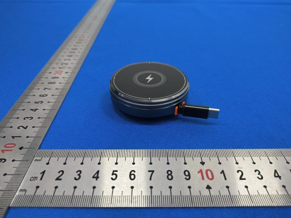
Click to zoom
Application Details
- Equipment Class
- DCD - Part 15 Low Power Transmitter Below 1705 kHz
- Date of Grant
- Aug 01, 2024
- Application Purpose
- Original Equipment
- Date of Application
- Aug 01, 2024
- Equipment Note
- 3-IN-1 Magnetic Wireless Charger
- Frequency Range
- 0.11000000 - 0.20500000
- Country
- China
Documents & Files
Document Text
Text extracted from the exhibit documents filed with the FCC. Open a document above to read the original.
Users Manual
FCC Warning Statement Changes or modifications not expressly approved by the party responsible for compliance could void the user’s authority to operate the equipment. This equipment has been tested and found to comply with the limits for a Class B digital device, pursuant to Part 15 of the FCC Rules. These limits are designed to provide reasonable protection against harmful interference in a residential installation. This equipment generates uses and can radiate radio frequency energy and, if not installed and used in accordance with the instructions, may cause harmful interference to radio communications. However, there is no guarantee that interference will not occur in a particular installation. If this equipment does cause harmful interference to radio or television reception, which can be determined by turning the equipment off and on, the user is encouraged to try to correct the interference by one or more of the following measures: ‐‐ Reorient or relocate the receiving antenna. ‐‐ Increase the separation between the equipment and receiver. ‐‐ Connect the equipment into an outlet on a circuit different from that to which the receiver is connected. ‐‐ Consult the dealer or an experienced radio/TV technician for help. FCC Radiation Exposure Statement The antennas used for this transmitter must be installed to provide a separation distance of at least 20 cm from all persons and must not be co‐located for operating in conjunction with any other antenna or transmitter. This device complies with Part 15 of the FCC Rules. Operation is subject to the following two conditions: (1)Thisdevicemaynotcauseharmfulinterference. (2)Thisdevicemustacceptanyinterferencereceived, includinginterferencethatmaycauseundesired operation.
Attestation Statements
Shenzhen Maokai Innovation Technology Co., Ltd. 2.911 (d)(5)(i) Equipment Type Attestation v1.2 Section 2.911(d)(5)(i) Certification – Equipment Type Company name: Shenzhen Maokai Innovation Technology Co., Ltd. Address: 2309 Jiaanda Building, Huafan Road, Dalang Street, Longhua District, Shenzhen, China Product Name: 3-IN-1 Magnetic Wireless Charger FCC ID: 2BHJE-M1 Model(s): M1 2.911(d)(5)(i) Equipment Type We, [Shenzhen Maokai Innovation Technology Co., Ltd.] (“the applicant”) certify that the equipment for which authorization is sought through certification is not: Prohibited from receiving an equipment authorization pursuant to § 2.903; of the FCC rules. Identified as an equipment type in the “Covered List” NOTE 1 Yours sincerely, Name: Tianshu Zhu Date: Jul. 23, 2024 Title and Company name: Manager; Shenzhen Maokai Innovation Technology Co., Ltd. NOTE 1 “Covered List”; is the List of Equipment and Services Covered By Section 2 of The Secure Networks Act, available at https://www.fcc.gov/supplychain/coveredlist References; 1) 986446 D01 Covered Equipment v01 https://apps.fcc.gov/oetcf/kdb/forms/FTSSearchResultPage.cfm?switch=P&id=325672 2) Federal Register document 2022-28263 published on 02/06/23 https://www.federalregister.gov/documents/2023/02/06/2022-28263/protecting-against-national-security-threats-to-the-com munications-supply-chain-through-the
Attestation Statements
Shenzhen Maokai Innovation Technology Co., Ltd. 2.911 (d)(5)(ii) Applicant Attestation v1.2 Section 2.911(d)(5)(ii) Certification – Applicant (Covered List ) Company name: Shenzhen Maokai Innovation Technology Co., Ltd. Address: 2309 Jiaanda Building, Huafan Road, Dalang Street, Longhua District, Shenzhen, China Product Name: 3-IN-1 Magnetic Wireless Charger FCC ID: 2BHJE-M1 Model(s): M1 2.911(d)(5)(ii) Applicant filing We, [Shenzhen Maokai Innovation Technology Co., Ltd.] (“the applicant”) certify that, as of the date of the filing of the application, the applicant is not identified NOTE 1 on the “Covered List” NOTE 2 , established pursuant to § 1.50002 of this chapter, as an entity producing covered communications equipment. Yours sincerely, Name: Tianshu Zhu Date: Jul. 23, 2024 Title and Company name: Manager; Shenzhen Maokai Innovation Technology Co., Ltd. NOTE 1 Delete option not applicable to this application. NOTE 2 “Covered List”; is the List of Equipment and Services Covered By Section 2 of The Secure Networks Act, available at https://www.fcc.gov/supplychain/coveredlist References; 1) 986446 D01 Covered Equipment v01 https://apps.fcc.gov/oetcf/kdb/forms/FTSSearchResultPage.cfm?switch=P&id=325672 2) Federal Register document 2022-28263 published on 02/06/23 https://www.federalregister.gov/documents/2023/02/06/2022-28263/protecting-against-national-security-threats-to-the-com munications-supply-chain-through-the
Cover Letter(s)
Shenzhen Maokai Innovation Technology Co., Ltd. Agent Authorization Company: Shenzhen Maokai Innovation Technology Co., Ltd. Address: 2309 Jiaanda Building, Huafan Road, Dalang Street, Longhua District, Shenzhen, China Product Name: 3-IN-1 Magnetic Wireless Charger Model Number(s): M1 Product Description: 3-IN-1 Magnetic Wireless Charger We authorize MiCOM Labs Inc., 575 Boulder Court, Pleasanton, California 94566, USA, to act on our behalf on all matters concerning the certification of above named equipment. We declare that MiCOM Labs Inc. is allowed to forward all information related to the approval and certification of equipment to the regulatory agencies as required and to discuss any issues concerning the approval application. Any and all acts carried out by MiCOM Labs on our behalf shall have the same effect as acts of our own. Signature: Date: Jul. 23, 2024 Name: Tianshu Zhu Title: Manager Company: Shenzhen Maokai Innovation Technology Co., Ltd.
Cover Letter(s)
< Shenzhen Maokai Innovation Technology Co., Ltd. > Office of Engineering Technology Federal Communications Commission 7435 Oakland Mills Road Columbia, MD21046 Date: Jul. 23, 2024 Subject; Request for Long Term Confidentiality FCC ID: 2BHJE-M1 To Whom It May Concern, Pursuant to the provisions of the Commission’s rules Title 47 Sections §0.457 and §0.459, we are requesting the Commission to withhold the following attachment(s) as confidential documents from public disclosure indefinitely. These documents contain detailed system and equipment descriptions and are considered as proprietary information in operation of the equipment. The public disclosure of these documents might be harmful to our company and would give competitors an unfair advantage in the market. Schematic Diagram Block Diagram Parts List Operational Description Tune-up Procedure It is our understanding that all measurement test reports, FCC ID label format and correspondence during the certification review process cannot be granted as confidential documents and this information will be available for public review once the grant of equipment authorization is issued. Sincerely, Signature: Name: Tianshu Zhu Title: Manager
Cover Letter(s)
< Shenzhen Maokai Innovation Technology Co., Ltd. > Office of Engineering Technology Federal Communications Commission 7435 Oakland Mills Road Columbia, MD21046 Date: Jul. 23, 2024 Subject; Request for Long Term Confidentiality FCC ID: 2BHJE-M1 To Whom It May Concern, Pursuant to the provisions of the Commission’s rules Title 47 Sections §0.457 and §0.459, we are requesting the Commission to withhold the following attachment(s) as confidential documents from public disclosure indefinitely. These documents contain detailed system and equipment descriptions and are considered as proprietary information in operation of the equipment. The public disclosure of these documents might be harmful to our company and would give competitors an unfair advantage in the market. Schematic Diagram Block Diagram Parts List Operational Description Tune-up Procedure It is our understanding that all measurement test reports, FCC ID label format and correspondence during the certification review process cannot be granted as confidential documents and this information will be available for public review once the grant of equipment authorization is issued. Sincerely, Signature: Name: Tianshu Zhu Title: Manager
External Photos
Model: M1 Model: M1 Model: M1
ID Label/Location Info
FCC ID LABEL: Label Location: FCC ID: 2BHJE-M1
ID Label/Location Info
FCC ID LABEL: Label Location: FCC ID: 2BHJE-M1
Internal Photos
Model: M1 Model: M1 Model: M1 Model: M1 Model: M1 Coil Antenna-Phone Model: M1 Coil Antenna-Watch Model: M1 Model: M1 Model: M1 Model: M1
RF Exposure Info
Page 1 of 15 Report No.: UNIA24071012ER-62 FCC MPE TEST REPORT FCC ID: 2BHJE-M1 Sample : 3-IN-1 Magnetic Wireless Charger Trade Mark : N/A Main Model : M1 Additional Model : N/A Report No. : UNIA24071012ER-62 Prepared for Shenzhen Maokai Innovation Technology Co., Ltd. 2309 Jiaanda Building, Huafan Road, Dalang Street, Longhua District, Shenzhen, China Prepared by Shenzhen United Testing Technology Co., Ltd. D101&D401, No. 107, Kaicheng High-Tech Park, Taoyuan Community, Dalang Sub-District, Longhua District, Shenzhen, Guangdong, China Page 2 of 15 Report No.: UNIA24071012ER-62 TEST RESULT CERTIFICATION Applicant .............................. : Shenzhen Maokai Innovation Technology Co., Ltd. Address ................................. : 2309 Jiaanda Building, Huafan Road, Dalang Street, Longhua District, Shenzhen, China Manufacturer ........................ : Shenzhen Maokai Innovation Technology Co., Ltd. Address ................................. : 2309 Jiaanda Building, Huafan Road, Dalang Street, Longhua District, Shenzhen, China Product description Product .................................. : 3-IN-1 Magnetic Wireless Charger Trade Mark............................. : N/A Model Name .......................... : M1 Standards .......................... : FCC KDB680106 D01 Wireless Power Transfer v04 This device described above has been tested by Shenzhen United Testing Technology Co., Ltd., and the test results show that the equipment under test (EUT) is in compliance with the FCC requirements. And it is applicable only to the tested sample identified in the report. This report shall not be reproduced except in full, without the written approval of UNI, this document may be altered or revised by Shenzhen United Testing Technology Co., Ltd., personnel only, and shall be noted in the revision of the document. Date of Test Date (s) of performance of tests ............ : Jul. 11, 2024 ~ Jul. 18, 2024 Date of Issue ......................................... : Jul. 19, 2024 Test Result ............................................. : Pass Edited by: Jason Ye Reviewed by: Kelly Cheng Approved by: Liuze Page 3 of 15 Report No.: UNIA24071012ER-62 Table of Contents Pages 1 TEST SUMMARY 4 1.1 TEST PROCEDURES AND RESULTS 4 1.2 TEST FACILITY 5 1.3 MEASUREMENT UNCERTAINTY 6 1.4 ENVIRONMENTAL CONDITIONS 6 2 GENERAL INFORMATION 7 2.1 GENERAL DESCRIPTION OF EUT 7 2.2 CARRIER FREQUENCY OF CHANNELS 8 2.3 TEST MODE 8 2.4 DESCRIPTION TEST PERIPHERAL AND EUT PERIPHERAL 9 2.4 TEST INSTRUMENTS 9 3 MAXIMUM PERMISSIBLE EXPOSURE 10 3.1 MAXIMUM PERMISSIBLE EXPOSURE 10 3.2 TEST PROCEDURE 11 3.3 TEST SETUP 11 3.4 RESULT OF MAXIMUM PERMISSIBLE EXPOSURE 12 3.5 TEST PHOTO 13 Page 4 of 15 Report No.: UNIA24071012ER-62 1 TEST SUMMARY 1.1 TEST PROCEDURES AND RESULTS FCC KDB680106 D01 Wireless Power Transfer v04 FCC CFR 47 Standard Section Test Item Result Remark FCC CFR 47 part1, 1.1310 KDB680106 D01 v04 Electric Field Strength (E) (V/m) N/A -- Magnetic Field Strength (H) (A/m) PASS -- Note: “N/A” denotes test is not applicable in this Test Report. Compliant with FCC KDB680106 D01 Wireless Power Transfer v04 section 5.2: 1) The power transfer frequency is below 1MHz. Yes, the working frequency is: 110-205kHz . 2) The output power from each transmitting element (e.g., coil) is less than or equal to 15 watts. Yes, the maximum output power is 15 watts. 3) A client device providing the maximum permitted load is placed in physical contact with the transmitter(i.e. , the surfaces of the transmitter and client device enclosures need to be in physical contact) Yes, the maximum permitted load is placed in physical contact with the transmitter. 4) Only $ 2.1091-Mobile exposure conditions apply (i.e., this provision does not cover $ 2.1093-Portable exposure conditions). Yes, this provision does not cover $ 2.1093-Portable exposure conditions. 5) The H-field strengths, at and beyond 20 cm surrounding the device surface, are demonstrated to be less than 50% of the applicable MPE limit, per KDB 447498, Table 1. These measurements shall be taken along the principal axes of the device, with one axis oriented along the direction of the estimated maximum field strength, and for three points per axis or until a 1/d (inverse distance from the emitter structure) field strength decay is observed. Symmetry considerations may be used for test reduction purposes. The device shall be operated in documented worst-case compliance scenarios(i.e. , the ones that lead to the maximum field components), and while all the radiating structures (e.g., coils or antennas) that by design can simultaneously transmit are energized at their nominal maximum power. Yes, The H-field strengths, at and beyond 20 cm surrounding the device surface, are demonstrated to be less than 50% of the applicable MPE limit ; coils or antennas) that by design can simultaneously transmit are energized at their nominal maximum power. Page 5 of 15 Report No.: UNIA24071012ER-62 6) For systems with more than one radiating structure, the conditions specified in (5) must be met when the system is fully loaded (i.e., clients absorbing maximum power available), and with all the radiating structures operating at maximum power at the same time, as per design conditions. If the design allows one or more radiating structures to be powered at a higher level while other radiating structures are not powered, then those cases must be tested as well. For instance, a device may use three RF coils powered at 5 W, or one coil powered at 15 W: in this case, both scenarios shall be tested. Yes, For systems with more than one radiating structure, the conditions specified in (5) must be met when the system is fully loaded (i.e., clients absorbing maximum power available), and with all the radiating structures operating at maximum power at the same time. 1.2 TEST FACILITY Test Firm : Shenzhen United Testing Technology Co., Ltd. Address : D101&D401, No. 107, Kaicheng High-Tech Park, Taoyuan Community, Dalang Sub…
Text truncated - open the document above for the full version.
RF Exposure Info
Page 1 of 15 Report No.: UNIA24071012ER-62 FCC MPE TEST REPORT FCC ID: 2BHJE-M1 Sample : 3-IN-1 Magnetic Wireless Charger Trade Mark : N/A Main Model : M1 Additional Model : N/A Report No. : UNIA24071012ER-62 Prepared for Shenzhen Maokai Innovation Technology Co., Ltd. 2309 Jiaanda Building, Huafan Road, Dalang Street, Longhua District, Shenzhen, China Prepared by Shenzhen United Testing Technology Co., Ltd. D101&D401, No. 107, Kaicheng High-Tech Park, Taoyuan Community, Dalang Sub-District, Longhua District, Shenzhen, Guangdong, China Page 2 of 15 Report No.: UNIA24071012ER-62 TEST RESULT CERTIFICATION Applicant .............................. : Shenzhen Maokai Innovation Technology Co., Ltd. Address ................................. : 2309 Jiaanda Building, Huafan Road, Dalang Street, Longhua District, Shenzhen, China Manufacturer ........................ : Shenzhen Maokai Innovation Technology Co., Ltd. Address ................................. : 2309 Jiaanda Building, Huafan Road, Dalang Street, Longhua District, Shenzhen, China Product description Product .................................. : 3-IN-1 Magnetic Wireless Charger Trade Mark............................. : N/A Model Name .......................... : M1 Standards .......................... : FCC KDB680106 D01 Wireless Power Transfer v04 This device described above has been tested by Shenzhen United Testing Technology Co., Ltd., and the test results show that the equipment under test (EUT) is in compliance with the FCC requirements. And it is applicable only to the tested sample identified in the report. This report shall not be reproduced except in full, without the written approval of UNI, this document may be altered or revised by Shenzhen United Testing Technology Co., Ltd., personnel only, and shall be noted in the revision of the document. Date of Test Date (s) of performance of tests ............ : Jul. 11, 2024 ~ Jul. 18, 2024 Date of Issue ......................................... : Jul. 19, 2024 Test Result ............................................. : Pass Edited by: Jason Ye Reviewed by: Kelly Cheng Approved by: Liuze Page 3 of 15 Report No.: UNIA24071012ER-62 Table of Contents Pages 1 TEST SUMMARY 4 1.1 TEST PROCEDURES AND RESULTS 4 1.2 TEST FACILITY 5 1.3 MEASUREMENT UNCERTAINTY 6 1.4 ENVIRONMENTAL CONDITIONS 6 2 GENERAL INFORMATION 7 2.1 GENERAL DESCRIPTION OF EUT 7 2.2 CARRIER FREQUENCY OF CHANNELS 8 2.3 TEST MODE 8 2.4 DESCRIPTION TEST PERIPHERAL AND EUT PERIPHERAL 9 2.4 TEST INSTRUMENTS 9 3 MAXIMUM PERMISSIBLE EXPOSURE 10 3.1 MAXIMUM PERMISSIBLE EXPOSURE 10 3.2 TEST PROCEDURE 11 3.3 TEST SETUP 11 3.4 RESULT OF MAXIMUM PERMISSIBLE EXPOSURE 12 3.5 TEST PHOTO 13 Page 4 of 15 Report No.: UNIA24071012ER-62 1 TEST SUMMARY 1.1 TEST PROCEDURES AND RESULTS FCC KDB680106 D01 Wireless Power Transfer v04 FCC CFR 47 Standard Section Test Item Result Remark FCC CFR 47 part1, 1.1310 KDB680106 D01 v04 Electric Field Strength (E) (V/m) N/A -- Magnetic Field Strength (H) (A/m) PASS -- Note: “N/A” denotes test is not applicable in this Test Report. Compliant with FCC KDB680106 D01 Wireless Power Transfer v04 section 5.2: 1) The power transfer frequency is below 1MHz. Yes, the working frequency is: 110-205kHz . 2) The output power from each transmitting element (e.g., coil) is less than or equal to 15 watts. Yes, the maximum output power is 15 watts. 3) A client device providing the maximum permitted load is placed in physical contact with the transmitter(i.e. , the surfaces of the transmitter and client device enclosures need to be in physical contact) Yes, the maximum permitted load is placed in physical contact with the transmitter. 4) Only $ 2.1091-Mobile exposure conditions apply (i.e., this provision does not cover $ 2.1093-Portable exposure conditions). Yes, this provision does not cover $ 2.1093-Portable exposure conditions. 5) The H-field strengths, at and beyond 20 cm surrounding the device surface, are demonstrated to be less than 50% of the applicable MPE limit, per KDB 447498, Table 1. These measurements shall be taken along the principal axes of the device, with one axis oriented along the direction of the estimated maximum field strength, and for three points per axis or until a 1/d (inverse distance from the emitter structure) field strength decay is observed. Symmetry considerations may be used for test reduction purposes. The device shall be operated in documented worst-case compliance scenarios(i.e. , the ones that lead to the maximum field components), and while all the radiating structures (e.g., coils or antennas) that by design can simultaneously transmit are energized at their nominal maximum power. Yes, The H-field strengths, at and beyond 20 cm surrounding the device surface, are demonstrated to be less than 50% of the applicable MPE limit ; coils or antennas) that by design can simultaneously transmit are energized at their nominal maximum power. Page 5 of 15 Report No.: UNIA24071012ER-62 6) For systems with more than one radiating structure, the conditions specified in (5) must be met when the system is fully loaded (i.e., clients absorbing maximum power available), and with all the radiating structures operating at maximum power at the same time, as per design conditions. If the design allows one or more radiating structures to be powered at a higher level while other radiating structures are not powered, then those cases must be tested as well. For instance, a device may use three RF coils powered at 5 W, or one coil powered at 15 W: in this case, both scenarios shall be tested. Yes, For systems with more than one radiating structure, the conditions specified in (5) must be met when the system is fully loaded (i.e., clients absorbing maximum power available), and with all the radiating structures operating at maximum power at the same time. 1.2 TEST FACILITY Test Firm : Shenzhen United Testing Technology Co., Ltd. Address : D101&D401, No. 107, Kaicheng High-Tech Park, Taoyuan Community, Dalang Sub…
Text truncated - open the document above for the full version.
Test Report
东莞市鑫旺线圈科技有限公司 Dongguan CityXinwang Coil Technology Co., Ltd 地址( Add ) : 东莞市塘厦镇横塘工业区新兴路 92 号 2 栋 6 楼 Add: Room 601, Building 2, No. 92, Xinxing Road, Hengtang Industrial Zone, Tangxia Town, Dongguan City 电话( Tel ) : 13662722286 传真( Fax ) : 产品规格承认书 SPECIFICATON APPROVAL 客户名称: CUSTOMER 深圳市瀚彩电子有限公司 客户品名: Product Name ofCustomer 线圈模组 Coil 我方产品名(材质): Product Mame ofOurs(Matenial) 线圈模组 Coil 承 认: APPROVED 核准: 制表:王兴旺 日期:2024-6-19 APPROVED DRAWN DATE Specification 规格内容 CISTOMEP/N: 客户品名 线圈模组Coil PARTNUMBER: 制造商料号 1.DIMENSIONS(外形尺寸):mm A 5.3±0.5 B 13.4±0.2 C 39±1 D 43.5±0.5 E 13±1 F 2-5 G Total thickness 1.8MAX H Diskette thickness 0.8±0.1 I J k L M N O R Q P APPROVED BY 承 认 CHECKED BY 审 查 PREPARED BY 制 作 DATE 日 期 PACE 页 码 黄艳平 王兴旺 2024-6-19 2 of 4 Specifcation 规 格 内 容 CUSTOMERP/N: 客户品名 线圈模组 Coil PARTNUMBER: 制造商料号 5.WINDING DETAILS(绕线详细说明): Wdy.NO. 绕 组 Start 开始 Finish 结束 Turns 圈数 Wire Dia 线径 Wdg.TyepeSprad/lose 绕线方法疏/密绕 Wdg.Directio n 绕线方向 Turns/Layer 层数/每层圈数 S F 12TS 0.08*24*2P 密绕 逆时针 1层/12TS 6.ELECTRICAL CHARACTERISTICS(电气特性): PARAMETERS UNIN LIMTI Inductance ls@100KHz/1v UH 6.8UH±5% Q @100KHz/1v 30MIN DCR @100KHz/1v Ω 0.15MAX APPROVED BY 承 认 CHECKED BY 审 查 PREPARED BY 制 作 DATE 日期 PAGE 页码 黄艳平 王兴旺 2024-6-19 3 of 4 MATERIAL LIST 材 料 清 单 CUSTOMER P/N: 客 户 品 名 线圈模组 Coil PARTNUMBER: 制造商料号 NO. Material name 材料名称 Description 品名描述 Manufacturer 制造商 Material 材质 1 Hot Stranded wire 0.08*24*2P 99.95%紫铜 2 Lead-free tin strip 高温 3 High temperature adhesive 金手指6mm 4 glue Resin 5 Magnetic sheet 43.5*5.3*0.8MM 铁氧体.锰锌PC40 6 Double-sided tape 手撕位背胶 7 EPE 270*380*55 8 carton 280*390*190 APPROVED BY 承 认 CHECKED BY 审 查 PREPARED BY 制作 DATE 日期 PAGE 页码 黄艳平 王兴旺 2024-6-19 4 of 4
Test Report
惠州启泰电子科技有限公司 HuizhouQitaiElectronicTechnologyCo.,LTD SPECIFICATIONSSHEET CUSTOMER: 客户 DESCRIPTION: 品名描述 CUSTOMERP/N: 客户品名 PARTNUMBER: 制造商料号 DATEOFAPPLICATION: 提出日期 瀚彩 2024-7-11 CLASSIFICATIONOFSPEC.PRESENTATION.(Ticktherelevantbox"√") oNewapplication新规格 √Newpartisaddedtoacceptedspecification新产品规格追加记录 oRevisionofacceptedspecification既存规格图面变更 ACCEPTANCESTAMP() APPROVALBY 承认 CHECKBY 审查 PREPAREBY 制作 ADDRESS:3rdFloor,No.181,Mingyue2ndRoad,ShiwanTown,BoluoCounty,Huizhoucity TELPHONE:0752-6668681 E-MAIL:[email protected] 惠州启泰电子科技有限公司 HuizhouQitaiElectronicTechnologyCo.,LTD HistoryForRevisedSpecification CUSTOMERP/N: 客户品名 PARTNUMBER: 制造商料号 Item 项次 DESCRIPTION(ContentOrReasonForChanged) 变更内容 Rev. 版本 CustRev. 客户版本 Date 日期 Revisor 修订者 1 InitialRelease(初版发行) A0 2024-7-11 冯欣 APPROVEDBY 承认 CHECKEDBY 审查 PREPAREDBY 制作 DATE 日期 PAGE 页码 晁子奇 冯欣 2024-7-11 1of3 惠州启泰电子科技有限公司 HuizhouQitaiElectronicTechnologyCo.,LTD Specification 规格内容 CUSTOMERP/N: 客户品名 PARTNUMBER: 制造商料号 1.DIMENSIONS():(Unit:mm) 单位(Unit):毫米(mm) ABCDEF 21Max 14.5±0.57.5±0.530±328±32±1 1.背胶为白色背胶,φ18.0。 2.磁铁规格:φ 7.5*2.5 ,磁场: 3600GS:。 3.带一根282MM热缩套管。 4.硬磁出线处开线槽。 APPROVEDBY 承认 CHECKEDBY 审查 PREPAREDBY 制作 DATE 日期 PAGE 页码 2024-7-11 2of3 惠州启泰电子科技有限公司 HuizhouQitaiElectronicTechnologyCo.,LTD Specification 规格内容 CUSTOMERP/N: 客户品名 PARTNUMBER: 制造商料号 2.WINDINGDETAILS(绕线详细说明) Coil1 圈数 Turns 线径 WireDia 绕线方式疏/密 Wdg.Type Spred/Close 绕线方向 Wdg.Direction 相交是/否 Intersect Yes/Not 13TS 0.08*24P热风绞线(HotAir strandedWire) 密绕(Close) 逆绕 是(Yes) 3.电气特性(ELECTRICALCHARACTERISTICS): 温度TEMPERATURE:25±10,RELATIVEHUMIDITY:6510% 序号 NO. 项目 ITEM 端子 TERMINAL 标准 SPECIFICATION 测试条件 TESTFREQUENCY 测试仪器 TESTEQUIPMENTS Coil1 1.INDS-F 7.5uh-8.1uh 100kHz/VUC2906A 2. QS-F 20Min 100kHz/VUC2906A 3.DCRS-F 145Max 100kHz/VUC2906A APPROVEDBY 承认 CHECKEDBY 审查 PREPAREDBY 制作 DATE 日期 PAGE 页码 2024-7-11 3of3
Test Report
Page 1 of 24 Report No.: UNIA24071012ER-61 FCC RADIO TEST REPORT FCC ID: 2BHJE-M1 Sample : 3-IN-1 Magnetic Wireless Charger Trade Mark : N/A Main Model : M1 Additional Model : N/A Report No. : UNIA24071012ER-61 Prepared for Shenzhen Maokai Innovation Technology Co., Ltd. 2309 Jiaanda Building, Huafan Road, Dalang Street, Longhua District, Shenzhen, China Prepared by Shenzhen United Testing Technology Co., Ltd. D101&D401, No. 107, Kaicheng High-Tech Park, Taoyuan Community, Dalang Sub-District, Longhua District, Shenzhen, Guangdong, China Page 2 of 24 Report No.: UNIA24071012ER-61 TEST RESULT CERTIFICATION Applicant ............................... : Shenzhen Maokai Innovation Technology Co., Ltd. Address .................................. : 2309 Jiaanda Building, Huafan Road, Dalang Street, Longhua District, Shenzhen, China Manufacturer ........................ : Shenzhen Maokai Innovation Technology Co., Ltd. Address .................................. : 2309 Jiaanda Building, Huafan Road, Dalang Street, Longhua District, Shenzhen, China Product description Product ................................... : 3-IN-1 Magnetic Wireless Charger Trade Mark ............................. : N/A Model Name ........................... : M1 Test Methods ........................ : FCC Rules and Regulations Part 15 Subpart C Section 15.209 ANSI C63.10: 2013 This device described above has been tested by Shenzhen United Testing Technology Co., Ltd., and the test results show that the equipment under test (EUT) is in compliance with the FCC requirements. And it is applicable only to the tested sample identified in the report. This report shall not be reproduced except in full, without the written approval of UNI, this document may be altered or revised by Shenzhen United Testing Technology Co., Ltd., personnel only, and shall be noted in the revision of the document. Date of Test Date (s) of performance of tests ............. : Jul. 11, 2024 ~ Jul. 18, 2024 Date of Issue .......................................... : Jul. 19, 2024 Test Result ............................................. : Pass Edited by: Jason Ye Reviewed by: Kelly Cheng Approved by: Liuze Page 3 of 24 Report No.: UNIA24071012ER-61 Table of Contents Pages 1 TEST SUMMARY 4 1.4 ENVIRONMENTAL CONDITIONS 6 2 GENERAL INFORMATION 7 2.1 GENERAL DESCRIPTION OF EUT 7 2.2 CARRIER FREQUENCY OF CHANNELS 8 2.3 TEST MODE 8 3 CONDUCTED EMISSION 11 3.1 TEST LIMIT 11 3.2 TEST SETUP 11 3.3 TEST PROCEDURE 12 3.4 TEST RESULT 12 4 RADIATED EMISSION 15 4.1 TEST LIMIT 15 4.2 TEST SETUP 17 4.3 TEST PROCEDURE 18 4.4 TEST RESULT 18 5 ANTENNA REQUIREMENT 22 6 PHOTO OF TEST 23 6.1 RADIATED EMISSION 23 6.2 CONDUCTED EMISSION 24 Page 4 of 24 Report No.: UNIA24071012ER-61 1 TEST SUMMARY 1.1 TEST PROCEDURES AND RESULTS Item FCC Rules Description Of Test Result 1 FCC Part 15.207 Conducted Emission Pass 2 FCC Part 15.209 Radiated Emission Pass 3 FCC Part 15.203 Antenna Requirement Pass Page 5 of 24 Report No.: UNIA24071012ER-61 1.2 TEST FACILITY Test Firm : Shenzhen United Testing Technology Co., Ltd. Address : D101&D401, No. 107, Kaicheng High-Tech Park, Taoyuan Community, Dalang Sub-District, Longhua District, Shenzhen, Guangdong, China The testing quality ability of our laboratory meet with "Quality Law of People's Republic of China" Clause 19.The testing quality system of our laboratory meets with ISO/IEC-17025 requirements. This approval result is accepted by MRA of APLAC. Our test facility is recognized, certified, or accredited by the following organizations: A2LA Certificate Number: 4747.01 The EMC Laboratory has been accredited by A2LA, and in compliance with ISO/IEC 17025:2017 General Requirements for testing Laboratories. FCC Registration Number: 674885 The EMC Laboratory has been registered and fully described in a report filed with the (FCC) Federal Communications commission. IC Registration Number: 31584 The EMC Laboratory has been registered and fully described in a report filed with the (IC) Industry Canada. Page 6 of 24 Report No.: UNIA24071012ER-61 1.3 MEASUREMENT UNCERTAINTY The reported uncertainty of measurement y ± U, where expended uncertainty U is based on a standard uncertainty multiplied by a coverage factor of k=2, providing a level of confidence of approximately 95 %. A. Conducted Measurement: Test Site Method Measurement Frequency Range U, (dB) NOTE UNI ANSI 9KHz ~ 150KHz 2.96 -- 150KHz ~ 30MHz 2.44 -- B. Radiated Measurement: Test Site Method Measurement Frequency Range U, (dB) NOTE UNI ANSI 9KHz ~ 30MHz 2.50 -- 30MHz ~ 1000MHz 4.80 -- 1000MHz ~ 6000MHz 4.13 -- 1.4 ENVIRONMENTAL CONDITIONS During the measurement the environmental conditions were within the listed ranges: Temperature: 15~35 °C Relative Humidity: 30~60 % Air Pressure: 950~1050 hPa Page 7 of 24 Report No.: UNIA24071012ER-61 2 GENERAL INFORMATION 2.1 GENERAL DESCRIPTION OF EUT Product: 3-IN-1 Magnetic Wireless Charger Trade Mark: N/A Main Model: M1 Additional Model: N/A Model Difference: N/A FCC ID: 2BHJE-M1 Operation Frequency: 110-205kHz Modulation Type: ASK Wireless Charging Output Power: Phone: 5W/7.5W/10W/15W(MAX) Earphone: 5W(MAX) Watch: 2.5W(MAX) Antenna Type: Coil Antenna Antenna Gain: 0dBi Battery: N/A Adapter: N/A Power Source: DC 5V/9V/12V by adapter Page 8 of 24 Report No.: UNIA24071012ER-61 2.2 CARRIER FREQUENCY OF CHANNELS Test Channel ANT Frequency (KHz) ANT Frequency (KHz) 01 128.2 02 132.5 2.3 TEST MODE NO. TEST MODE DESCRIPTION 1 ANT 1 + Full load (Connect to adapter) 2 ANT 1 + Half load (Connect to adapter) 3 ANT 1 + Null load (Connect to adapter) 4 ANT 1(Full load) + Earphone Battery station 99% (Connect to adapter) 5 ANT 1(Half load) + Earphone Battery station 50% (Connect to adapter) 6 ANT 1(Null load) + Earphone Battery station 1% (Connect to adapter) 7 ANT 2 + Watch Battery station 99% (Connect to adapter) 8 ANT 2 + Watch Battery station 50% (Connect to adapter) 9 ANT 2 + Watch Battery station 1% (Connect to adapter) 10 ANT 1(Full load) + ANT 2 (Watch Battery s…
Text truncated - open the document above for the full version.
Test Report
Page 1 of 24 Report No.: UNIA24071012ER-61 FCC RADIO TEST REPORT FCC ID: 2BHJE-M1 Sample : 3-IN-1 Magnetic Wireless Charger Trade Mark : N/A Main Model : M1 Additional Model : N/A Report No. : UNIA24071012ER-61 Prepared for Shenzhen Maokai Innovation Technology Co., Ltd. 2309 Jiaanda Building, Huafan Road, D…
Text truncated - open the document above for the full version.
Contact Information
Applicant
Tianshu Zhu
Technical Contact
Test Firm
Shenzhen United Testing Technology Co., Ltd.Ze Liu
[email protected]86-755-86180996
Technical Specifications
| # | Rule Parts | Frequency Range | Power Output |
|---|---|---|---|
| 1 | 15C | 0.11 MHz - 0.205 MHz | - |