2BHLS-ADX400Microphone
Guangdong Moken Trading Co., Ltd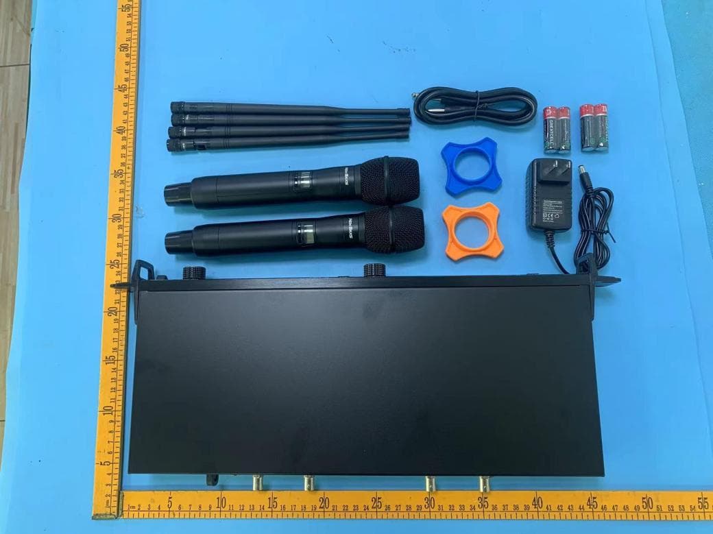
Click to zoom
Application Details
- Equipment Class
- DWM - Part 15 Wireless Microphone
- Date of Grant
- Jul 21, 2024
- Application Purpose
- Original Equipment
- Date of Application
- Jul 21, 2024
- Equipment Note
- Microphone
- Frequency Range
- 657.25000000 - 662.75000000
- Country
- China
Documents & Files
Document Text
Text extracted from the exhibit documents filed with the FCC. Open a document above to read the original.
Users Manual
USER GUIDE English Products in kind prevail 8 Technical specifications System parameter: Carrier frequency: Modulation mode: Bandwidth: Channel: Frequency stability: Dynamic range: Maximum modulation: . Harmonic distortion: Frequency response: False interference ratio: Signal-to-noise ratio: Operating temperature: ± ≤5% 68KHz 100Hz - 2KHz 80dB >55d UHF 657.25~ 662.75MHz FM 50MHz 2×200 channel ±0.005% >105dB B -10°C ―+40°C Receiver Power source: Power consumption: Receiver sensitivity: Audio output: Mixed output: Balanced output: DC15V/500mA 3W dB mu V (80dB S/N) 0-200mV, 0-400mV, LOW: > 15 hours Transmitter Emission power: maximum: 25mW ; minimum: 15mW WBattery: 3V(1.5VAa×2) Continuous use time: High:-> 10 hours 9 Warning: Changes or modifications to this unit not expressly approved by the party responsible for compliance could void the users authority to operate the equipment. NOTE: This device complies with part 15 of the FCC Rules. Operation is subject to the following two conditions: (1) This device may not cause harmful interference, and (2) this device must accept any interference received, including interference that may cause undesired operation. FCC Statement: This equipment has been tested and found to comply with the limits for a Class B digital device, pursuant to part 15 of the FCC Rules. These limits are designed to provide reasonable protection against harmful interference in a residential installation. This equipment generates, uses and can radiate radio frequency energy and, if not installed and used in accordance with the instructions, may cause harmful interference to radio communications. However, there is no guarantee that interference will not occur in a particular installation. If this equipment does cause harmful interference to radio or television reception, which can be determined by turning the equipment off and on, the user is encouraged to try to correct the interference by one or more of the following measures: Reorient or relocate the receiving antenna. Increase the separation between the equipment and receiver. Connect the equipment into an outlet on a circuit different from that to which the receiver is connected. Consult the dealer or an experienced radio/TV technician for help. RF exposure compliance statement: This device has been evaluated to meet the general RF exposure requirement 7 See solution Power supply ,cable or radio frequency Gain ,cable ,reduce interference or radio frequency Radio frequency Interface locking problem There is no sound A weak or distorted sound Working distance is too short ,sudden noise or signal frequency loss Unable to turn off the transmitter or change the frequency settings ,or unable to program for the receiver Power Supply Ensure that the receiver and transmitter use sufficient voltage. Test battery indicator. Please replace the battery or charge it. gain The front of the receiver adjusts the system gain. It corresponds to the input of mixing panel, amplifier or processor. Cable Make sure all cables and connectors are fully engaged or locked in place, Check whether the cable is damaged. If necessary, please replace it. Interface locking Transmitters and receivers can be locked to prevent accidental or unauthorized changes. When accessing the lock controller, the lock icon on the display screen. Unlock the receiver or transmitter according to instructions. Radio Frequency (RF) The RF green light lights up when the linked transmitter is within the range of the receiver. Measure transmitter range before performance to avoid operating beyond specified transmitter range. The RF meter bar indicates the received RF power, Signals may be received from receivers or from interference sourc- es such as television broadcasting. If the signal level is dis- played on the meter when the transmitter is off, there may be interference in the channel, Check whether there are in- terference sources in the area around the fender or change the receiver to clear frequency. Red display, weak reception. Green display, strong reception. Eliminating Radio Frequency Overpower If the radio frequency 0L icon appears on the radio frequency scale, please try the following operation. Reduce transmitter RF power level from Hi to Lo. Move the transmitter to a position at least 6m(20in) from the receiver. If active antenna is used, the gain of antenna or amplifier should be reduced. Using omnidirectional antenna. Increase the scope Increase transmitter RF power level to Hi. Increase the radio frequency range by using an active directional antenna, an antenna distribution system, or other antenna accessories Frequency compatibility Perform "scan" and "synchronization" operations to ensure that transmitters and receivers are set to the same channel or frequency. Check tags on transmitters and receivers to ensure they use the same band. Reducing interference Perform a scan to find the optimal idle frequency. Perform IR synchronization to transfer settings to the transmitter. If there are multiple systems, make sure that each receiver is assigned to a unique channel. If two transmitters are set to phase The same channel will cause interference. It should be ensured that there are no obstacles in the line of sight between the transmitter and the receiver. Keep the receiver antenna away from metal objects or other radio frequency interference sources (such as CD players, computers, digital effects, network switches, wires and personal stereo monitors (PSM) and other wireless systems). Eliminate excessive RF signal (see below). Troubleshooting 6 Receiver Display Screen 1.2 channel indication Volume gain of receiver Adjustable by knob Receiver Frequency Marshalling Display Receiver channel display Receiver Frequency Display Receiver audio quality display 3 4 5 1 2 6 Transmitter power display When the remaining grid is left, the power symbol will flicker. 7 8 9 Display of transmitter type Hand held, Purse Lock-up Display of Receiver Receiver operation instructio…
Text truncated - open the document above for the full version.
Attestation Statements
GuangdongMokenTradingCo.,Ltd Rev1/26/2023 FederalCommunicationsCommission AuthorizationandEvaluationDivision 7435OaklandMillsRoad Columbia,MD21046 USA Date:2024/7/16 Ref:AttestationStatementsPart2.911(d)(5)(i)Filing FCCID:2BHLS-ADX400 GuangdongMokenTradingCo.,Ltd(“theapplicant”)certifiesthattheequipmentforwhich authorizationissoughtisnot“covered”equipmentprohibitedfromreceivinganequipment authorizationpursuanttosection2.903oftheFCCrules. Sincerely, (Applicantsignature) ContactName:JianpengXu
Attestation Statements
GuangdongMokenTradingCo.,Ltd Rev1/26/2023 FederalCommunicationsCommission AuthorizationandEvaluationDivision 7435OaklandMillsRoad Columbia,MD21046 USA Date:2024/7/16 Ref:AttestationStatementsPart2.911(d)(5)(ii)Filing FCCID:2BHLS-ADX400 GuangdongMokenTradingCo.,Ltd(“theapplicant”)certifiesthat,asofthedateofthefilingofthe application,theapplicantisnotidentifiedontheCoveredList(asaspecificallynamedentityoranyofits subsidiariesoraffiliates)asanentityproducing“covered” equipment. Sincerely, (Applicantsignature) ContactName:JianpengXu
Attestation Statements
GuangdongMokenTradingCo.,Ltd Rev1/26/2023 FederalCommunicationsCommission AuthorizationandEvaluationDivision 7435OaklandMillsRoad Columbia,MD21046 USA Date:2024/7/16 Ref:AttestationStatementsPart2.911(d)(7)Filing FCCIDorGranteeCode:FCCID:2BHLS-ADX400or2BHLS ApplicantFRN:0035693746 GuangdongMokenTradingCo.,Ltd(“theapplicant”)certifiesthat,asofthedateofthefilingofthe application,REPAmericaLLCisourdesignatedU.S.agentforserviceofprocessfortheabovereferenced FCCID.GuangdongMokenTradingCo.,Ltdacceptstomaintainanagentfornolessthanoneyearafter thegranteehasterminatedallmarketingandimportationortheconclusionofanyCommission-related proceedinginvolvingtheequipment. REPAmericaLLCaccepts,asofthedateofthefilingoftheapplication,theobligationofthedesignated U.S.agentforserviceofprocessfortheabovereferencedFCCID. DesignatedU.S.AgentInformation: Name:REPAmericaLLC U.S.AgentFRN:0034192500 Address:REPAmericaLLC,1942BroadwaySt.STE314CBoulder,CO80302UnitedStates ContactPerson:MrBenXu Tel.:(719)201-3314 Email:[email protected] Sincerely, JianpengXuMrBenXu GuangdongMokenTradingCo.,LtdREPAmericaLLC [InsertApplicantsignature][U.S.Agentsignature]
Cover Letter(s)
GuangdongMokenTradingCo.,Ltd Rev11/20/07 FederalCommunicationsCommission AuthorizationandEvaluationDivision ConfidentialityRequestregardingapplicationforcertificationofFCCID:2BHLS-ADX400. PursuanttoSections0.457and0.459oftheCommission’sRules,weherebyrequestconfidential treatmentofinformationaccompanyingthisapplicationasoutlinedbelow: ExhibitType Schematics Blockdiagram Operationdescription Theabovematerialscontaintradesecretsandproprietaryinformationnotcustomarilyreleasedto thepublic.Thepublicdisclosureofthesematerialsmaybeharmfultotheapplicantandprovide unjustifiedbenefitstoitscompetitors. TheapplicantunderstandsthatpursuanttoSection0.457oftheRules,disclosureofthis applicationandallaccompanyingdocumentationwillnotbemadebeforethedateoftheGrant forthisapplication. PursuanttoDA04-1705June15,2004oftheCommission’spublicnotice,wealsorequest temporaryconfidentialtreatmentofinformationaccompanyingthisapplicationasoutlinedbelow: ExhibitType Sincerely, (signature) JianpengXu
Cover Letter(s)
GuangdongMokenTradingCo.,Ltd M:\MasterDocuments\TEMPLATES\POA_Letter.doc FederalCommunicationsCommission AuthorizationandEvaluationDivision 7435OaklandMillsRoad Columbia,MD21046 Date:2024/7/16 SUBJECT:FCCApplicationforFCCID:2BHLS-ADX400 ToWhomItMayConcern: We,theundersigned,herebyauthorizeBenTangatShenzhenDACETestingTechnology Co.,Ltd.onourbehalf,toapplytotheFederalCommunicationsCommissiononour equipment.AnyandallactscarriedoutbyShenzhenDACETestingTechnologyCo.,Ltd. onourbehalfshallhavethesameeffectasactsofourown. ThisistoadvisethatweareinfullcompliancewiththeAnti-DrugAbuseAct.We,the applicant,arenotsubjecttoadenialoffederalbenefitspursuanttoSection5301ofthe Anti-DrugActof1988,21USC853a,andnopartytotheapplicationissubjecttoadenial offederalbenefitspursuanttothatsection. Regards, (signature) JianpengXu
External Photos
FCCID:2BHLS-ADX400 External FCCID:2BHLS-ADX400 FCCID:2BHLS-ADX400 FCCID:2BHLS-ADX400
ID Label/Location Info
Label:40*30mm MicrophoneModel:ADX400 FCCID:2BHLS-ADX400MadeinChina Thisdevicecomplieswithpart15oftheFCCRules.Operationissubjecttothefollowingtwoconditions: (1)Thisdevicemaynotcauseharmfulinterference,and (2)thisdevicemustacceptanyinterferencereceived,includinginterferencethatmaycauseundesired operation.
Internal Photos
FCCID:2BHLS-ADX400 Internal FCCID:2BHLS-ADX400 FCCID:2BHLS-ADX400 FCCID:2BHLS-ADX400 FCCID:2BHLS-ADX400
RF Exposure Info
Page1of1 RFExposureEvaluationReport 1RFEXPOSURE ProductName:Microphone ModelNo:ADX400 FCCID:2BHLS-ADX400 NOTE:accordingtoKDB447498D01GeneralRFExposureGuidancev06 , Unlessspecifically requiredbythepublishedRFexposureKDBprocedures,standalone1-gheadorbodyand10-g extremitySARevaluationforgeneralpopulationexposureconditions,bymeasurementornumerical simulation,isnotrequiredwhenthecorrespondingSARTestExclusionThresholdcondition(s), listedbelow,is(are)satisfied. For100MHzto6GHzandtestseparationdistances≤50mm,the1-gand10-gSARtest exclusionthresholdsaredeterminedbythefollowing: TheEUTisaportabledevice [(max.powerofchannel,includingtune-uptolerance,mW)/(min.testseparationdistance, mm)]·[√f(GHz)]≤3.0for1-gSAR,and≤7.5for10-gextremitySAR,where f(GHz)istheRFchanneltransmitfrequencyinGHz PoweranddistanceareroundedtothenearestmWandmmbeforecalculation Theresultisroundedtoonedecimalplaceforcomparison Theproductisusedatadistanceof5mmfromthehumanbody. Here, 1.1EUTRFEXPOSUREEVALUATION OperationalMode:EDR Channel (MHz) MaximumPeak Conducted OutputPower (dBm) Tuneup tolerance (dB) Maximum tune-up Power (dBm) Maximum tune-up Power (mW) Calculated value Exclusion threshold 662.75-11.654 -11±1 -100.1000.0313 Conclusion:thecalculatedvalue≤3.0,SARisexempted.
Test Report
SPECIFICATION 深圳市华信通讯科技有限公司 Shenzhen Huaxin Communication Technology Co., Ltd. 深圳市华信通讯科技有限公司 Shenzhen Huaxin Communication Technology Co., Ltd. 客户确认: 装配是否符合贵司要求:□ L150 Product Specifications OK□NG Page 2 Electrical technical parameters 电 性 能 指 标 Electrical Specifications 频率范围657.25MHz~662.75MHz Frequency Range 657.25MHz~662.75MHz 电压驻波比≤1.5 VSWR ≤1.5 增益 0dBiGAIN0dBi 输入阻抗 50 ΩInput Impedance50 Ω 机 械 指 标 Mechanical Specifications 天线颜色 黄色 Antenna Color yellow 接口形式 针孔 Input connector pinhole 线长度 120mmCable length120mm 工作温度-40°C~+85°C Working Temperature -40°C~+85°C 工作湿度 20~80%Working Humidity20~80% Antenna picture: Page 4 Network Analysis Test: VSWR 、Return loss 、Smith 公司地址:深圳市龙华区观湖街道环观南茂源工业园D栋3楼电话:0755-88298396传真:0755-89733896 http://www.szgdtrf.com Page 5
Test Report
V1.0ReportNo.:DACE240708006RL001 102,BuildingH1,&1/F.,BuildingH,HongfaScience&TechnologyPark,TangtouConnunity,ShiyanSubdistrict,Bao'anDistrict,Shenzhen,Guangdong,China Web:http://www.dace-lab.comTel:+86-755-23010613E-mail:[email protected] 1 of 46 RFTESTREPORT For GuangdongMokenTradingCo.,Ltd ProductName:Microphone TestModel(s).:ADX400 ReportReferenceNo.:DACE240708006RL001 FCCID:2BHLS-ADX400 Applicant’sName:GuangdongMokenTradingCo.,Ltd Address: Oneofthesecondfloors,No.1,Lane5,Zone2,Team11,Fei'etang Village,EnchengStreet,EnpingCity TestingLaboratory:ShenzhenDACETestingTechnologyCo.,Ltd. Address: 102BuildingH1&1/F.,BuildingH,HongfaScience&TechnologyPark, Tangtou,Shiyan,Bao’anDistrict,Shenzhen,Guangdong,China TestSpecificationStandard:47CFRPart15.236 DateofReceipt:July8,2024 DateofTest:July8,2024toJuly11,2024 DataofIssue:July11,2024 Result:Pass Note:Thisreportshallnotbereproducedexceptinfull,withoutthewrittenapprovalofShenzhenDACE TestingTechnologyCo.,Ltd.ThisdocumentmaybealteredorrevisedbyShenzhenDACETestingTechnology Co.,Ltd.personnelonly,andshallbenotedintherevisionsectionofthedocument.Thetestresultsinthe reportonlyapplytothetestedsample V1.0ReportNo.:DACE240708006RL001 102,BuildingH1,&1/F.,BuildingH,HongfaScience&TechnologyPark,TangtouConnunity,ShiyanSubdistrict,Bao'anDistrict,Shenzhen,Guangdong,China Web:http://www.dace-lab.comTel:+86-755-23010613E-mail:[email protected] 2 of 46 RevisionHistoryOfReport VersionDescriptionREPORTNo.IssueDate V1.0OriginalDACE240708006RL001July11,2024 NOTE1: Themanufacturershouldensurethatallproductsinseriesproductionareinconformitywiththeproductsampledetailedin thisreport.Iftheproductinthisreportisusedinanyconfigurationotherthanthatdetailedinthereport,themanufacturer mustensurethenewsystemcomplieswithallrelevantstandards. Compiledby:Supervisedby:Approvedby: BenTang/TestEngineerTomChen/ProjectEngineerMachaelMo/Manager V1.0ReportNo.:DACE240708006RL001 102,BuildingH1,&1/F.,BuildingH,HongfaScience&TechnologyPark,TangtouConnunity,ShiyanSubdistrict,Bao'anDistrict,Shenzhen,Guangdong,China Web:http://www.dace-lab.comTel:+86-755-23010613E-mail:[email protected] 3 of 46 CONTENTS 1TESTSUMMARY...................................................................................................................................................4 1.1TESTSTANDARDS........................................................................................................................................4 1.2SUMMARYOFTESTRESULT.........................................................................................................................4 2GENERALINFORMATION....................................................................................................................................5 2.1CLIENTINFORMATION..................................................................................................................................5 2.2DESCRIPTIONOFDEVICE(EUT)..................................................................................................................5 2.3DESCRIPTIONOFTESTMODES....................................................................................................................6 2.4DESCRIPTIONOFSUPPORTUNITS................................................................................................................6 2.5EQUIPMENTSUSEDDURINGTHETEST........................................................................................................6 2.6STATEMENTOFTHEMEASUREMENTUNCERTAINTY......................................................................................8 2.7IDENTIFICATIONOFTESTINGLABORATORY...................................................................................................8 2.8ANNOUNCEMENT.........................................................................................................................................8 3EVALUATIONRESULTS(EVALUATION).............................................................................................................9 3.1ANTENNAREQUIREMENT..............................................................................................................................9 3.1.1Conclusion:...................................................................................................................................9 4RADIOSPECTRUMMATTERTESTRESULTS(RF).........................................................................................10 4.1CONDUCTEDOUTPUTPOWER....................................................................................................................10 4.1.1E.U.T.Operation:........................................................................................................................10 4.1.2TestSetupDiagram:...................................................................................................................10 4.1.3TestData:...................................................................................................................................10 4.2CHANNELBANDWIDTH...............................................................................................................................13 4.2.1E.U.T.Operation:........................................................................................................................13 4.2.2TestSetupDiagram:...................................................................................................................13 4.2.3TestData:...................................................................................................................................14 4.3NECESSARYBANDWIDTH...........................................................................................................................16 4.3.1E.U.T.Operation:........................................................................................................................17 4.3.2TestSetupDiagram:............................................................…
Text truncated - open the document above for the full version.
Test Setup Photos
FCCID:2BHLS-ADX400 Emissionsinfrequencybands(30M-1GHz) Emissionsinfrequencybands(Above1GHz)
Contact Information
Applicant
Jianpeng Xu
Test Firm
Shenzhen DACE Testing Technology Co., Ltd.Colin Huang
[email protected]86 13267178997
Technical Specifications
| # | Rule Parts | Frequency Range | Power Output |
|---|---|---|---|
| 1 | 15C | 657.25 MHz - 662.75 MHz | 70.00 µW |