2BK98ALANBT01Alan Safety BT module
Alan Safety Company Limited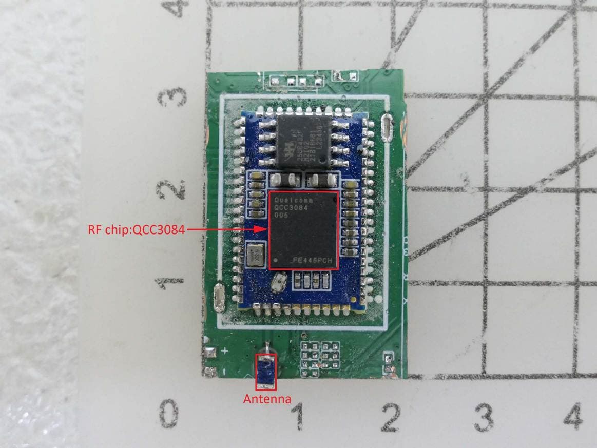
Click to zoom
Application Details
- Equipment Class
- DSS - Part 15 Spread Spectrum Transmitter
- Date of Grant
- Mar 09, 2026
- Application Purpose
- Original Equipment
- Equipment Note
- Alan Safety BT module
- Frequency Range
- 2402.00000000 - 2480.00000000
- Company
- Alan Safety Company Limited
- Country
- Taiwan
Documents & Files
Document Text
Text extracted from the exhibit documents filed with the FCC. Open a document above to read the original.
Users Manual
SPECIFICATION Product:BLUETOOTH MODULE SPEC. :BRM3084 Model Number: DC-SP-V04170331 Alan Safety Company ALANBT01 2 ListofContents 1Introduction...............................................................................................................3 2KeyFeatures.............................................................................................................3 3Applications..............................................................................................................4 4BlockDiagram...........................................................................................................4 5Generalspecifications..............................................................................................4 6ModulePackageInformation....................................................................................5 6.1PinoutDiagramandpackagedimensions......................................................5 6.2ModulePindescriptions..................................................................................6 7ElectricalCharacteristics......................................................................................10 7.1AbsoluteMaximumRatings...........................................................................10 7.2RecommendedOperatingConditions...........................................................10 8Recommendedreflowtemperatureprofile............................................................12 Alan Safety Company 3 1Introduction introducesthepioneeroftheBluetooth 5.3modules whichisahighperformance,costeffective,lowpower andcompactsolution.TheBluetoothmoduleprovidesacomplete2.4GHz BluetoothsystembasedontheQCC3084WLCSPchipsetwhichisasingle chipradioandbasebandICforBluetooth2.4GHzsystems.Thismoduleisfully [email protected]. 2KeyFeatures MD-BLT-QR3084I(QCC3084)Features QualifiedtoBluetoothv5.3specification 240MHzQualcomm®Kalimba™audioDSP 32/80MHzDeveloperProcessorforapplications FirmwareProcessorforsystem FlexibleQSPIflashprogrammableplatform High-performance24-bitstereoaudiointerface Digitalandanalogmicrophoneinterfaces FlexiblePIOcontrollerandLEDpinswithPWMsupport Serialinterfaces:UART,BitSerializer(I²C/SPI),USB2.0 Advancedaudioalgorithms ActiveNoiseCancellation:Hybrid,Feedforward,andFeedbackmodes,using DigitalorAnalogMics,enabledusinglicensekeysavailablefromQualcomm® Qualcomm®aptX ™ andaptXHDAudio aptXAdaptive,enabledusinglicensekey 1or2micQualcomm®cVc™headsetspeechprocessing Qualcomm®cVc ™ NoiseCancellationTechnology,enabledusinglicensekey IntegratedPMU:DualSMPSforsystem/digitalcircuits,IntegratedLi-ionbattery charger 134-ball6.7mmx7.4mmx1.0mm,0.5mmpitchVFBGA Applicationsubsystem Dual-coreapplicationsubsystem32/80MHzoperation 32-bitFirmwareProcessor(reservedforsystemuse)executes: Bluetoothupperstack Profiles House-keepingcode 32-bitDeveloperProcessorexecutes: Developerapplications BothcoresexecutecodefromexternalflashmemoryusingQSPIclockedat32 MHzor80MHz On-chipcachespercoreenableoptimizedperformanceandpowerconsumption Bluetoothsubsystem QualifiedtoBluetoothv5.3specificationincluding2MbpsBluetoothLowEnergy andBluetoothLowEnergyIsochronousChannels Qualcomm®BluetoothHighSpeedLink Singleendedantennaconnectionwithon-chipbalunandTx/Rxswitch Bluetooth,BluetoothLowEnergy,andmixedtopologiessupported Class1support Alan Safety ALANBT01 Alan Safety Company 4 3Applications Wired/wirelessstereoheadsets/headphones 4BlockDiagram 5Generalspecifications ModelName ProductDescriptionBluetooth5.3Class1.5Module BluetoothStandardBluetooth5.3 ChipsetQCC3084WLCSP Dimension13mmx20mmx2.8mm OperatingConditions Voltage2.8~4.3V Temperature-40~+85°C StorageTemperature-40~+85°C ElectricalSpecifications FrequencyRange2402~2480MHz MaximumRFTransmitPower13dBm π/4DQPSKReceiveSensitivity-94dBm 8DPSKReceiveSensitivity-88dBm ALANBT01 Alan Safety Company 5 6ModulePackageInformation 6.1PinoutDiagramandpackagedimensions Unit:MM RecommendedPCBlayoutfootprint Alan Safety Company 6 6.2ModulePindescriptions Alan Safety Company 7 Pin#PinNamePintypeDescription 1MIC_4PAnalog Microphonedifferential4input,positive. Alternativefunction: ■Differentialaudiolineinput4,positive 2MIC_4NAnalog Microphonedifferential4input,negative. Alternativefunction: ■Differentialaudiolineinput4,negative 3PIO[20] Digital:Bidirectionalwith programmablestrength internalpull-up/pull-down ProgrammableI/Oline20. Alternativefunction: ■PCM_DOUT[1] 4PIO[19] Digital:Bidirectionalwith programmablestrength internalpull-up/pull-down ProgrammableI/Oline19. Alternativefunction: ■PCM_DIN[0] 5PIO[18] Digital:Bidirectionalwith programmablestrength internalpull-up/pull-down ProgrammableI/Oline18. Alternativefunction: ■PCM_DOUT[0] 6PIO[17] Digital:Bidirectionalwith programmablestrength internalpull-up/pull-down ProgrammableI/Oline17. Alternativefunction: ■PCM_SYNC 7PIO[16] Digital:Bidirectionalwith programmablestrength internalpull-up/pull-down ProgrammableI/Oline16. Alternativefunction: ■PCM_CLK 8PIO[15] Digital:Bidirectionalwith programmablestrength internalpull-up/pull-down ProgrammableI/Oline15. Alternativefunction: ■MCLK_OUT 9VBAT_SENSEAnalogBatteryvoltagesenseinput. 10USB_DNDigitalUSBFullSpeeddeviceD-I/O. 11USB_DPDigitalUSBFullSpeeddeviceD+I/O. 12VCHGSupplySupplytoSMPSpowerswitchfrombattery. 13VCHG_SENSEAnalog Chargerinputsensepin.High impedance.ConnectVCHG_SENSE directtoSMPS_VCHG. 14CHG_EXTAnalog Externalchargertransistorcurrent control.Connecttobaseofexternal chargertransistorasperapplication schematic. 15SYS_CTRLDigitalinput TypicallyconnectedtoanON/OFFpush button.Ifpowerispresentfromthe batteryand/orcharger,andsoftwarehas placedthedeviceintheOFFor DORMANTstate,abuttonpressboots thedevice.Alsousableasadigitalinput innormaloperation.Nopull. Additionalfunction: ■PIO[0]inputonly Alan Safety Company 8 16VBATSupplyBatteryvoltageinput. 17GNDGroundGround 18AIO0/LED0 Analogordigitalinput/ opendrainoutput. General-purposeanalog/digitalinputor opendrainLEDoutput. 19A…
Text truncated - open the document above for the full version.
Attestation Statements
Federal Communicaons Commission Authorizaon and Evaluaon Division 7435 Oakland Mills Road Columbia, MD 21046 USA Date: 12/02/2026 Ref: A estaon Statement P art 2.911(d)(7) Filing FCC ID: 2BK98ALANBT01 ALAN-SAFETY COMPANY LIMITED cerfies that, as of the dates of this applicaon, Americas Compliance Consulng LLC dba iCerfi is our designated U.S. agent for service of process for the above referenced FCC ID. Manufacturer accepts to maintain an agent for no less than two year aer the grantee has terminated all markeng and importaon or the conclusion of any commission-related proceeding involving the equipment. iCerfi accepts, as of the date of the filing of the applicaon, the obligaon of the designated U .S. ag ent f or service process for the above r eferenced FCC ID . Designated U.S. Agent Informaon: Name: Americas Compliance Consulng LLC dba iCerfi FCC FRN: 0033399411 Address: 5809 US-2, Suite B , Albeni Plaza Priest Riv er, Idaho 83856, United St ates Contact P erson: Paul Pr eston Tel: +1 (866) 885-4575 Email: fccagent@icerfi.com Sincerely, ALAN-SAFETY COMPANY LIMITEDAmericas Compliance Consulng LLC dba iCerfi FRN: 0035983287FRN: 0033399411 Andy ChenPaul Pr eston [email protected]@icerfi.com 06-273-9975+1 (866) 885-4575 Signature: Signature:
Cover Letter(s)
RF_160_05 Declaration of Authorisation Date of issue 02-01-2023 Declaration of Authorization We Name: ALAN-SAFETY COMPANY LIMITED Address: No.36, Alley 38, Lane 288, Heshun Rd. Sec.1 Guiren Dist., City: Tainan City, 71145, Country: Taiwan(R.O.C.) Declare that: Name Representative of agent: Jerry Liu.......... (1) Agent Company name: International Standards Laboratory Corp. Address: No. 120, Lane 180, Hsin Ho Rd., Lung-Tan Dist., City: Tao Yuan City 325. Country Taiwan is authorized to apply for Certification of the following product(s): Product description: Alan Safety BT module Type designation: ALANBT01 Trademark: Qualcomm Validity/ expiry date on our behalf. Date: 2026/02/09.. City: Tainan City .. Name: Andy Chen .. (2) Function: VP of Executive............................... Signature: . Notes: (1): Required for FCC application (2): For FCC it must be the Grantee Code “owner” or the authorized agent. Revision Record Sheet: Revision Section number Page number Date Remark(s) issued by 02 1 02-01-2023 History sheet added AG Issued/modified by : Axel Gase Function : Quality Manager Revision : 02 Date : 02-01-2023 Verified by : Willem Jan Jong Function : Team Lead Date : 02-01-2023 Released by : Axel Gase Function : Manager Quality Assurance Date of release: : 02-01-2023
Cover Letter(s)
FCC, Request for non-disclosure Date: 02-01-2023 RF_501, Issue 10 Page 1 of 1 Company Name: ALAN-SAFETY COMPANY LIMITED Address: No.36, Alley 38, Lane 288, Heshun Rd. Sec.1 Guiren Dist., City: Tainan City, 71145, Country: Taiwan(R.O.C.) To: Kiwa Netherlands B.V., Dept. FCC TCB Wilmersdorf 50 7327 AC Apeldoorn The Netherlands Subject: Request for confidentiality FCC ID: 2BK98ALANBT01 Reference number: ###### Dear FCC TCB, 1. Long-Term Confidentiality Pursuant to 47 CFR Section 0.459(a) & (b), we hereby requests non-disclosure and confidential treatment of the following materials submitted in support of FCC certification application: Bill(s) of Material Block Diagrams Operational Description Schematic Diagrams Tune-up Procedure Above materials contain secrets, proprietary and technical information, which would customarily be guarded from competitors under 47 CFR, section 0.457(d)(2). Disclosure or publication or any portion of this company confidential material to other parties could cause substantial competitive harm and provide unjustified benefits for competitors. 2. Short-Term Confidentiality (STC) Pursuant to Public Notice DA 04-1705 of the Commission’s policy, in order to comply with the marketing regulations in 47 CFR §2.803 and the importation rules in 47 CFR §2.1204, applicant hereby requests Short-Term Confidential treatment of the following materials (See notes below): Internal Photos User’s Manual Test Set-up Photos External Photos Justification: Date: 2026/02/09 Name and signature of applicant: Andy Chen VP of Executive Notes: 1) A document or type of document can only have ONE type of confidentiality! 2) Short-Term confidentiality is in principle for 45 days from date of grant; it can be extended max 3 times (total time 180 days max.)! The planned date should state in the RF731 application form. 3) FCC must be informed when marketing begins earlier. 4) Release takes place automatically thus extension must be requested in time. Telefication does not remind you of this! 5) Request for extension or for release must be received by Kiwa NL B.V. at least 7 days before date of actual marketing or before expiration of the STC period FCC, Request for non-disclosure Date: 02-01-2023 RF_501, Issue 10 Page 1 of 1 Revision Record Sheet: Revision Section number Page number Date Remark(s) issued by 10 1 02-01-2023 History sheet added AG Issued/modified by : Axel Gase Function : Quality Manager Revision : 10 Date : 02-01-2023 Verified by : Willem Jan Jong Function : Team Lead Date : 02-01-2023 Released by : Axel Gase Function : Manager Quality Assurance Date of release: : 02-01-2023
Cover Letter(s)
RF_734_05 FCC Modular Approval Request Page 1 of 3 28-12-2022 Modular Approval Request FCC (KDB 996369 D01 & Part 15.212) FCC ID: _ 2BK98ALANBT01 _________________ Items to be covered by Single modular transmitters. Answer from applicant 1. The radio elements must have the radio frequency circuitry shielded. Physical components and tuning capacitor(s) may be located external to the shield, but must be on the module assembly. The module has a metal shielded. Refer to the external photo of EUT . 2. The module must have buffered modulation/data inputs to ensure that the device will comply with Part 15 requirements with any type of input signal. Data to the modulation circuit is buffered as described in the circuit/block diagram - The modulation inputs are buffered by the internal logic of the QCC3084 SOC provided with the application. 3. The module must contain power supply regulation on the module The module contains its own power supply regulation. Please refer to schematic as Li-lon Charger contain power regulation supplied to sub-functionality of the radio 4. The module must contain a permanently attached antenna, or contain a unique antenna connector, and be marketed and operated only with specific antenna(s), per §§ 15.203, 15.204(b), 15.204(c), 15.212(a), 2.929(b). Device is equipped with External Antenna with unique non standard antenna port, Chip Antenna. Refer to the photo of EUT. 5.The module must demonstrate compliance in a stand-alone configuration. The module was tested standalone as shown in test report setup photographs filed with this application. 6.The module must be labeled with its permanently affixed FCC ID label, or use an electronic display (see KDB Publication 784748). The modular has a permanent fixed label, and below statement was listed in the User Manual; The host device must be labeled to display the FCC ID of the module “Contains FCC ID: 2BK98ALANBT01” . 7.The module must comply with all specific rules applicable to the transmitter, including all the conditions provided in the integration instructions by the grantee. The module comply with all specific rules applicable to the transmitter including all the conditions provided in the integration instructions by the grantee, Refer to test report and user manual 8.The module must comply with RF exposure requirements. The transmitter meets MPE calculation of 47CFR§ 2.1091 & 47 CFR §1.1307. Refer to MPE Reports and Refer to modular installation manual. RF_734_05 FCC Modular Approval Request Page 2 of 3 28-12-2022 Items to be covered by Split modular transmitters. Answer from applicant 1. The modular transmitter must comply with all requirements of a single modular transmitter except for items (1) & (5) of the above single modular approval requirements. 2. Only the radio front end must be shielded. The physical crystal and tuning capacitors may be located external to the shielded radio elements. The interface between the split sections of the modular system must be digital with a minimum signalling amplitude of 150 mV peak-to-peak. 3. Control information and other data may be exchanged between the transmitter control elements and radio front end. 4. The sections of a split modular transmitter must be tested installed in a host device(s) similar to that which is representative of the platform(s) intended for use. 5. Manufacturers must ensure that only transmitter control elements and radio front end components that have been approved together are capable of operating together. The transmitter module must not operate unless it has verified that the installed transmitter control elements and radio front end have been authorized together. Manufacturers may use means including, but not limited to, coding in hardware and electronic signatures in software to meet these requirements, and must describe the methods in their application for equipment authorization. Note: A limited modular approval (LMA) may be granted for single or split modular transmitters that comply partially with the requirements above. Name and surname of applicant (or authorized representative): __ Andy Chen / VP of Executive _______________ Date: ___2026/02/09_________ Signature: RF_734_05 FCC Modular Approval Request Page 3 of 3 28-12-2022 Revision Record Sheet: Revision Section number Page number Date Remark(s) issued by 5 1 28-12-2022 History sheet added WJJ Issued/modified by : Willem Jan Jong Function : Team Lead Revision : 5 Date : 28-12-2022 Verified by : Axel Gase Function : Quality Manager Date : 28-12-2022 Released by : Axel Gase Function : Manager Quality Assurance Date of release: : 28-12-2022
External Photos
International Standards Laboratory Corp. Report Number: ISL-26LR0007P Appendix Photographs of EUT of Product Name Alan Safety BT module Main Model ALANBT01 Series Model NA Brand Qualcomm International Standards Laboratory Corp. Report Number: ISL-26LR0007P -1- EUT-1. EUT-2. International Standards Laboratory Corp. Report Number: ISL-26LR0007P -2- EUT-3.
ID Label/Location Info
FCC ID LABEL FORMAT AND LOCATION Applicant: ALAN-SAFETY COMPANY LIMITED FCC ID: 2BK98ALANBT01
Internal Photos
International Standards Laboratory Corp. Report Number: ISL-26LR0007P Appendix Photographs of EUT of Product Name Alan Safety BT module Main Model ALANBT01 Series Model NA Brand Qualcomm International Standards Laboratory Corp. Report Number: ISL-26LR0007P -1- EUT-1.
RF Exposure Info
FCC: 2BK98ALANBT01 International Standards Laboratory Maximum Permissible Exposure (MPE) Standard Applicable For The radiation source included into the device the output power is taken from a corresponding RF test report. If needed the output power is converted to source based, time – average out power. Finally the output power is compared to FCC and IC low power SAR evaluation exemption level. According to §2.1093 this is a Portable device. FCC SAR test exclusion: According to KDB 447498 D01 General RF Exposure Guidance v05r02, Appendix A requirement, “The equation and threshold in section 4.3.1 must be applied to determine SAR test exclusion.” 4.3.1. Standalone SAR test exclusion considerations Unless specifically required by the published RF exposure KDB procedures, standalone 1-g head or body and 10-g extremity SAR evaluation for general population exposure conditions, by measurement or numerical simulation, is not required when the corresponding SAR Test Exclusion Threshold condition, listed below, is satisfied. These test exclusion conditions are based on source-based time-averaged maximum conducted output power of the RF channel requiring evaluation, adjusted for tune-up tolerance, and the minimum test separation distance required for the exposure conditions.23 The minimum test separation distance is determined by the smallest distance from the antenna and radiating structures or outer surface of the device, according to the host form factor, exposure conditions and platform requirements, to any part of the body or extremity of a user or bystander (see 5) of section 4.1). To qualify for SAR test exclusion, the test separation distances applied must be fully explained and justified by the operating configurations and exposure conditions of the transmitter and applicable host platform requirements, typically in the SAR measurement or SAR analysis report, according to the required published RF exposure KDB procedures. When no other RF exposure testing or reporting is required, a statement of justification and compliance must be included in the equipment approval, in lieu of the SAR report, to qualify for the SAR test exclusion. When required, the device specific conditions described in the other published RF exposure KDB procedures must be satisfied before applying these SAR test exclusion provisions; for example, handheld PTT two-way radios, handsets, laptops & tablets etc.24 1) The 1-g and 10-g SAR test exclusion thresholds for 100 MHz to 6 GHz at test separation distances ≤ 50 mm are determined by: [(max. power of channel, including tune-up tolerance, mW)/(min. test separation distance, mm)] · [√f(GHz)] ≤ 3.0 for 1-g SAR and ≤ 7.5 for 10-g extremity SAR,25 where FCC: 2BK98ALANBT01 International Standards Laboratory • f(GHz) is the RF channel transmit frequency in GHz • Power and distance are rounded to the nearest mW and mm before calculation26 • The result is rounded to one decimal place for comparison • 3.0 and 7.5 are referred to as the numeric thresholds in the step 2 below The test exclusions are applicable only when the minimum test separation distance is ≤ 50 mm and for transmission frequencies between 100 MHz and 6 GHz. When the minimum test separation distance is < 5 mm, a distance of 5 mm according to 5) in section 4.1 is applied to determine SAR test exclusion. RSS 102 Issue 5 Mar. 2015 2.5.1 Exemption Limits for Routine Evaluation – SAR Evaluation SAR evaluation is required if the separation distance between the user and/or bystander and the antenna and/or radiating element of the device is less than or equal to 20 cm, except when the device operates at or below the applicable output power level (adjusted for tune-up tolerance) for the specified separation distance defined in Table 1. FCC: 2BK98ALANBT01 International Standards Laboratory Evaluation Result: FCC: Model: Frequency (MHz) Output Power (dBm) Antenna Gain (dBi) EIRP (dBm) Tune-up Tolerance (dB) Max Power (mW) Min Distance (mm) Result Limit (3.0 @ 1g SAR) 2402 2.51 3.00 5.51 0.5 4.00 5.00 1.24 3.0 ~ End ~
Test Report
2.4GHz Chip Antenna: AAN3216H4R2G45 ______________________________________________________________________________________________________ Application: WLAN, 802.11b/g, Bluetooth, etc... Features SMD, high reliability, ultra Impact, Omni-directional... Electrical Specification Working Frequency Range 2400 ~2484 MHz Peak Gain 3.0dBi (Typ.) Impedance 50 Ohm Return loss 10 dB ( Min) Polarization Linear Azimuth Beamwidth Omni-directional Operation Temperature(°C) -40 ~85°C The specification is defined on EVB. Dimension and Terminal Configuration Part number AAN 3216 H4 R 2G45 (1) (2) (3) (4) (5) (1)Product Type Chip Antenna (2) Size Code 3.2x1.6mm (3) Type Code H4 (4) Packing Tape and reel (5) Frequency 2.45GHz Dimension (mm) No. Terminal Name L 3.2 +-0.20 1 Feeding W 1.6+-0.20 2 Soldering T 1.20+-0.20 A 0.20+-0.20 2.4GHz 2.45HHz Chip Antenna: AAN3216H4R2G45 ______________________________________________________________________________________________________ Evaluation Board Reference PCB Dimension & Antenna Layout Reference unit :mm Electrical Characteristics Return Loss & Radiation Return Loss Frequency (MHz) S11 (dB) 2400 -12.8 2442 -19.8 2484 -11.9 Radiation 2.45GHz Frequency 2445MHz Peak gain 3.0dBi Efficiency 79.2% 2.4GHz 2.45HHz Chip Antenna: AAN3216H4R2G45 ______________________________________________________________________________________________________ Taping Specifications Reel Taping Blister Tape Checking note Index Spec (mm) Internal diameter of reel A 60.20 ± 0.50 External diameter of reel B 178 ± 1.00 Quantity/per reel 3000 pcs Tape material Plastic (embossed) Checking note Index Spec (mm) Sprocket hole D0 1.50 +0.10/-0.00 Distance sprocket hole to outside E1 1.75 ± 0.10 Distance sprocket hole to pocket F 5.50 ± 0.05 Distance sprocket hole to sprocket hole P0 4.00 ± 0.10 Distance pocket to pocket P1 4.00 ± 0.10 Distance sprocket hole to pocket P2 2.00 ± 0.05 Tape width W 12.00 +0.30/-0.10 Pocket width nominal clearance A0 2.28 ± 0.13 Pocket length nominal clearance B0 5.70 ± 0.13 Pocket depth minimum clearance K0 1.58 ± 0.10 Thickness of tape T 0.23 ± 0.02 2.4GHz 2.45HHz Chip Antenna: AAN3216H4R2G45 ______________________________________________________________________________________________________ Reliability Table Test ItemProcedure Requirements Ceramic Type Remark (Reference) Electrical Characterization Fulfill the electrical specification User Spec. Thermal Shock 1. Preconditioning: 50 ± 10°C / 1 hr , then keep for 24 ± 1 hrs at room temp. 2. Initial measure: Spec: refer Initial spec. 3. Rapid change of temperature test: -30°C to +85°C; 100 cycles; 15 minutes at Lower category temperature; 15 minutes at Upper category temperature. No Visible Damage. Fulfill the electrical specification. MIL-STD-202 107 Temperature Cycling 1. Initial measure: Spec: refer Initial spec. 2. 100 Cycles (-30°C to +85°C), Soak Mode=1 (2 Cycle/hours). 3. Measurement at 24 ± 2Hours after test condition. No Visible Damage. Fulfill the electrical specification. JESD22 JA104 High Temperature Exposure 1. Initial measure: Spec: refer Initial spec. 2. Unpowered; 500hours @ T=+85°C. 3. Measurement at 24 ± 2 hours after test. No Visible Damage. Fulfill the electrical specification. MIL-STD-202 108 Low Temperature Storage 1. Initial measure: Spec: refer Initial spec. 2. Unpowered: 500hours @ T= -30°C. 3. Measurement at 24 ± 2 hours after test. No Visible Damage. Fulfill the electrical specification. MIL-STD-202 108 Solderability (SMD Bottom Side) Dipping method: a. Temperature: 235 ± 5°C b. Dipping time: 3 ± 0.5s The solder should cover over 95% of the critical area of bottom side. IEC 60384-21/22 4.10 Soldering Heat Resistance (RSH) Preheating temperature: 150 ± 10°C. Preheating time: 1~2 min. Solder temperature: 260 ± 5°C. Dipping time: 5 ± 0.5s No Visible Damage.IEC 60384-21/22 4.10 Vibration5g's for 20 min., 12 cycles each of 3 orientations Note: Use 8"X5" PCB .031" thick 7 secure points on, one long side and 2 secure points at corners of opposite sides. Parts mounted within 2" from any secure point. Test from 10-2000 Hz. No Visible Damage.MIL-STD-202 Method 204 Mechanical Shock Three shocks in each direction shall be applied along the three mutually perpendicular axes of the test specimen (18 shocks) Peak value: 1,500g’s Duration: 0.5ms Velocity change: 15.4 ft/s Waveform: Half-sine No Visible Damage.MIL-STD-202 Method 213 Humidity Bias 1. Humidity: 85% R.H., Temperature: 85 ± 2 °C. 2. Time: 500 ± 24 hours. 3. Measurement at 24 ± 2hrs after test condition. No Visible Damage. Fulfill the electrical specification. MIL-STD-202 Method 106 2.4GHz 2.45HHz Chip Antenna: AAN3216H4R2G45 ______________________________________________________________________________________________________ Revision History Revision Date Content 1 2019/7/26New issue Board Flex (SMD) 1. Mounting method: IR-Reflow. PCB Size (L:100 × W:40 × T:1.6mm) 2. Apply the load in direction of the arrow until bending reaches 2 mm. No Visible Damage.AEC-Q200 005 AdhesionForce of 1.8Kg for 60 seconds.No Visible Damage Magnification of 20X or greater may be employed for inspection of the mechanical integrity of the device body terminals and body/terminal junction. AEC-Q200 006 Physical Dimension Any applicable method using x10 magnification, micrometers, calipers, gauges, contour projectors, or other measuring equipment, capable of determining the actual specimen dimensions. In accordance with specification. JESD22 JB100
Test Report
TEST REPORT of FCC CFR Title 47 Part 15 Subpart C Product: Alan Safety BT module Brand: Qualcomm Main Model: ALANBT01 Series Model: NA FCC ID: 2BK98ALANBT01 Standard: §15.247, Cat: DSS Reference: ANSI C63.10: 2020 KDB 558074 D01 v05r02 Applicant: ALAN-SAFETY COMPANY LIMITED Address No.36, Alley 38, Lane 288, Heshun Rd. Sec.1 Guiren Dist., Tainan City, 71145, Taiwan(R.O.C.) Test Performed by: International Standards Laboratory Corp. LT Lab. TEL: +886-3-263-8888 FAX: +886-3-263-8899 No. 120, Lane 180, Hsin Ho Rd., Lung-Tan Dist., Tao Yuan City 325, Taiwan Report No.: ISL-26LR0007FCDSS Issue Date : January 30, 2026 FCC Registration Number: 487532 Test results given in this report apply only to the specific sample(s) tested and are traceable to national or international standard through calibration of the equipment and evaluating measurement uncertainty herein. According to customer agreement, the laboratory issues test reports based on the regulations or standards specifications, the measurement uncertainty is not considered in conformity decision rules. This test report shall not be reproduced except in full, without the written approval of International Standards Laboratory Corp. -2 of 115- International Standards Laboratory Corp. Report Number: ISL-26LR0007FCDSS VERIFICATION OF COMPLIANCE Applicant: ALAN-SAFETY COMPANY LIMITED Equipment Under Test: Alan Safety BT module Brand: Qualcomm Main Model: ALANBT01 Series Model: NA Model Difference: N/A FCC ID: 2BK98ALANBT01 Date of Test: January 16, 2026 ~ January 30, 2026 Date of EUT Received: January 16, 2026 APPLICABLE STANDARDS STANDARD TEST RESULT FCC Part 15.247 Complied We hereby certify that: All the tests in this report have been performed and recorded in accordance with the standards de-scribed above and performed by an independent electromagnetic compatibility consultant, International Standards Laboratory Corp. The test results contained in this report accurately represent the measurements of the characteristics and the energy generated by sample equipment under test at the time of the test. The sample equipment tested as described in this report is in compliance with the limits of above standards. Prepared By: Gigi Yeh Test By: Approved By: Jason Chao Jerry Liu / Manager -3 of 115- International Standards Laboratory Corp. Report Number: ISL-26LR0007FCDSS Version Version No. Date Description 00 January 30, 2026 Initial creation of document -4 of 115- International Standards Laboratory Corp. Report Number: ISL-26LR0007FCDSS TABLE OF CONTENTS 1. Description of Equipment under Test (EUT) .......................................................................... 6 2. Description of Test Modes ......................................................................................................... 7 2.1 CONFIGURATION OF TESTED SYSTEM .............................................................................................. 7 3. Standards, reference documents and applicable test methods .............................................. 8 4. Summary of Test Results ........................................................................................................... 8 5. AC Line Conduced Emission Test ............................................................................................ 9 5.1 STANDARD APPLICABLE .................................................................................................................. 9 5.2 MEASUREMENT PROCEDURE............................................................................................................ 9 5.3 MEASUREMENT RESULT..................................................................................................................10 6. Peak Output Power Measurement ......................................................................................... 12 6.1 STANDARD APPLICABLE ......…
Text truncated - open the document above for the full version.
Contact Information
Applicant
Andy Chen
[email protected]Fax: +88662739388
Technical Contact
Americas Compliance consulting, LLC dba iCertifiPaul Preston
2445 NE Division Street, Suite 202 · United States
Test Firm
International Standards Laboratory Corp.Benson Chen
[email protected]Fax: 886-3-263-8899
Technical Specifications
| # | Rule Parts | Frequency Range | Power Output |
|---|---|---|---|
| 1 | 15C | 2.40 GHz - 2.48 GHz | 1.80 mW |