2BKJ3-MES-E100Bone Conduction Auxiliary Earphones
Shanghai mearsun Technology Co., Ltd.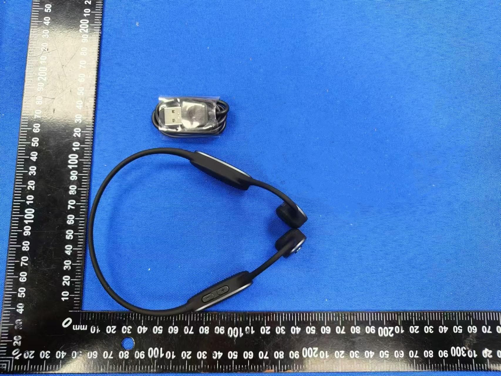
Click to zoom
Application Details
- Equipment Class
- DSS - Part 15 Spread Spectrum Transmitter
- Date of Grant
- Aug 29, 2024
- Application Purpose
- Original Equipment
- Date of Application
- Aug 27, 2024
- Equipment Note
- Bone Conduction Auxiliary Earphones
- Frequency Range
- 2402.00000000 - 2480.00000000
- Country
- China
Documents & Files
Document Text
Text extracted from the exhibit documents filed with the FCC. Open a document above to read the original.
Users Manual
The User Manual of Bone Conduction Auxiliary earphone Earphones I. Overview II. Product Parameters CONTENTS IV. Warnings and Cautions V. Battery Warnings VI. Warranty Card VII. Product Maintenance and Warranty III. User Instructions I. Overview 1.1 Product Information: Trademark: mearsun Model: MES-E100 Product Name: Bone Conduction Auxiliary earphone Earphones 1.2 Main Structures and Components: The earhook bone conduction Auxiliary earphone consists of a micro- phone, a signal processing unit, a bone conduction oscillator, a lithium battery, and a charging cable. 1.3 Intended Use: The bone conduction Auxiliary earphone is used to improve the hearing of hearing-impaired people. It can effectively improve the listening experi- ence of people with communication needs, and thus help them improve their communication skills. A. Ambient temperature range: -10-40 B. Avoid long-term high temperature, high humidity, or direct sunlight A B 1.5 Working Environment CD 1.4 Packing List: S N 1.6 Storage and Transportation Environment A. Adopt general cargo transportation methods; prevent direct exposure to sunlight, rain, and snow; avoid mechanical collisions. B. Long-term storage should be indoor with a temperature of -10-45, with ventilation and no corrosive gases. 2.1 Auxiliary earphone User Instructions: 1. Auxiliary earphone Product Diagram II. User Instructions switch key volume key Magnetic- charging port bone conduction oscillator multi-function key 2.Simulation headset button operation: Simulation headset switch: Long press the volume "+" button for 3 seconds to turn on manually (blue light); Long press the volume "+" button for 3 seconds to manually shut down (red light on); Bluetooth pairing: Long press the headset volume key "+" for 5 seconds, confirm that the red and blue lights alternately flash, and then turn on the authenticator, the screen shows Bluetooth matching, wait for a moment, Bluetooth automatic link, when the screen shows volume tuning, it means that the Bluetooth match is successful. Volume size: The volume varies from 0% to 100%, with the tone "drop" for SN each level. Press the + key to increase the volume. Press "-" Key for volume Decrease; When the volume is adjusted to the maximum or minimum, there will be a "drop" sound prompt. Answer a call: Click the multifunction key when a call comes in. Hang up: Click the multi-function key during a call. Reject incoming calls: Long press 2s multi-function button; The Simulated earphones are connected to Bluetooth earphones, and the use of APP to adjust the volume is invalid. Low power alarm: when low power, play a low power tone every 60 seconds; Low power prompt does not repeat the prompt after three times, the battery 3.1V automatic shutdown "drop". Power display: Connected to the mobile phone, the headset power will be displayed next to the Bluetooth icon in the status bar of the mobile phone (the display icon of the mobile phone system shall prevail). 3. Auxiliary earphone Charging and Battery Life: A. Charging and battery life: After the product is fully charged, it can be used for 14 continuous hours (the battery capacity will decay with use and time); B. The product can be charged with the magnetic charging cable included. The standard charging voltage is: 5v C. The charging indicator light is always red during charging and will turn blue when fully charged. A full charge takes about 2~3 hour. 2.3 Simulation headset fitting process: How to use APP fitting You can connect the APP on your smartphone via Bluetooth for smart fitting and customize your own listening mode. 1) Install the APP ● For Android phones, you can search, download and install the "Mei 'er Sound" APP through the App market. ● iPhone users can search, download and install the APP through APP Store .2) Connect to the APP ● Long press the volume button "+" on the headset for 5 seconds, and the red and blue lights flash alternately. Turn on the Bluetooth function of the mobile phone, find "mearsun" in the Bluetooth list of the mobile phone, and link. When the indicator shows blue, it means that the Bluetooth has been connect- ed and paired. ● Open the mobile APP, register an account, log in, the Bluetooth pairing page will be displayed, click the "click select device" button, the device list will appear, select "Mearsun" to adapt, complete the Bluetooth pairing. ● After pairing, enter the volume interface, you can adjust the total volume, or adjust the volume of the left and right ears. 3) APP matching ● Click "Enter Fitting" button in the sound adjustment interface, follow the normal procedure of fitting introduction, click "Start" button to officially enter Additional note: The headset turns on. It's a hearing aid. Activate the Bluetooth connection, and when playing music, the auxiliary listening function is paused. Bluetooth connection to play music while playing music temporarily stop, listen to start work again. As long as the headset is on, it is always in the working state. Auxiliary listening and player 2 the fitting interface, the default start is left ear fitting; ● Select a single frequency in order, the simulation headset will play "woo" or "toot" sound, and then slide the volume up and down to adjust, just hear the sound; ● After testing the last frequency, click the "Save" button. Will be prompted whether to perform the other right ear fitting, according to the prompt, select "no fitting" or "go to fitting" button. Repeat the process to complete the hearing test. ● After all the frequencies are tested, click the "Save" button, the fitting is finished, a fitting map will appear on the interface diagram, and the APP will save your audiogram to the product. The whole fitting process is over. The whole process takes about 3-5 minutes; 2.4 How to Wear Please wear the bone conduction simulation headset in the way shown below. In order to achieve a better wearing effect, please try to make the bone guide of the product fit in front of the ear. function…
Text truncated - open the document above for the full version.
Attestation Statements
ShanghaimearsunTechnologyCo.,Ltd. CERTIFICATIONSCONCERNING“COVERED”EQUIPMENT Date:2024-8-23 FederalCommunicationsCommission AuthorizationandEvaluationDivision 7435OaklandMillsRoad Columbia,Maryland21046 FCCID:2BKJ3-MES-E100 ToWhomItMayConcern: Asrequiredbysection2.911(d)(5)(i),[ShanghaimearsunTechnologyCo.,Ltd.](“the applicant”)certifiesthattheequipmentforwhichauthorizationissoughtisnot“covered” equipmentprohibitedfromreceivinganequipmentauthorizationpursuanttosection2.903 oftheFCCrules. Asrequiredbysection2.911(d)(5)(ii),[ShanghaimearsunTechnologyCo.,Ltd.](“the applicant”)certifiesthat,asofthedateofthefilingoftheapplication,theapplicant[isnot] identifiedontheCoveredListasanentityproducing“covered”equipment. Thankyouforyourattentiontothismatter. Sincerelyyours, Signature PrintedName:XuKe Company:ShanghaimearsunTechnologyCo.,Ltd. JobTitle:Manager Email:[email protected] Telephone:13917050701
Cover Letter(s)
ShanghaimearsunTechnologyCo.,Ltd. LETTEROFAGENCY Date:2024-8-23 FederalCommunicationsCommission AuthorizationandEvaluationDivision 7435OaklandMillsRoad Columbia,Maryland21046 FCCID:2BKJ3-MES-E100 ToWhomItMayConcern: Wecertifythatwearenotsubjecttodenialoffederalbenefits,thatincludesFCCbenefits, pursuanttoSection5301oftheAnti-DrugAbuseACTof1988,U.S.C.862.Further,no party,asdefinedin47CFR1.2002(b),totheapplication,issubjecttodenialoffederal benefits,thatincludesFCCbenefits. Thankyouforyourattentiontothismatter. Sincerelyyours, Signature PrintedName:XuKe Company:ShanghaimearsunTechnologyCo.,Ltd. JobTitle:Manager Email:[email protected] Telephone:13917050701
Cover Letter(s)
ShanghaimearsunTechnologyCo.,Ltd. RequestforLong-TermConfidentialityLetter-FCC Date:2024-8-23 FederalCommunicationsCommission AuthorizationandEvaluationDivision 7435OaklandMillsRoad Columbia,Maryland21046 Re:RequestforLong-Termconfidentiality FCCID:2BKJ3-MES-E100 Towhomitmayconcern, Weherebyrespectfullyrequestthatundertheprovisionof47CFR0.459and0.457(d)the documentslistedbelowandattachedwiththisapplicationforcertificationbeprovidedwithLong- Termconfidentialstatus. Schematics.pdf OperationalDescription.pdf FrequencyBlockDiagrams.pdf Anyexhibit/informationforwhichwehaverequestedconfidentiality,butwhichmaynotbe accordedsuchtreatmentbytheFCC,shouldbereturnedtous. Thedocumentslistedabovecontaintradesecretsthataretreatedasconfidentialbyus. Substantialcompetitiveharmtouscouldresultshouldtheybemadeavailabletothepublic. Sincerelyyours, Signature PrintedName:XuKe Company:ShanghaimearsunTechnologyCo.,Ltd. JobTitle:Manager Email:[email protected] Telephone:13917050701
External Photos
Overallviewofunit Overallviewofunit Overallviewofunit Overallviewofunit
Internal Photos
Internalviewofunit Internalviewofunit Internalviewofunit Internalviewofunit PCBviewofunit PCBviewofunit Antenna PCBviewofunit Batteryviewofunit
RF Exposure Info
FCCID:2BKJ3-MES-E100 RFExposureEvaluation AccordingtoKDB447498D01GeneralRFExposureGuidancev06andpart2.1093, UnlessspecificallyrequiredbythepublishedRFexposureKDBprocedures,standalone 1-gheadorbodyand10-gextremitySARevaluationforgeneralpopulationexposure conditions,bymeasurementornumericalsimulation,isnotrequiredwhenthe correspondingSARTestExclusionThresholdcondition(s),listedbelow,is(are)satisfied. For100MHzto6GHzandtestseparationdistances≤50mm,the1-gand10-gSARtest exclusionthresholdsaredeterminedbythefollowing: [(max.powerofchannel,includingtune-uptolerance,mW)/(min.testseparationdistance, mm)]·[√f (GHz) ]≤3.0for1-gSAR,and≤7.5for10-gextremitySAR,where f (GHz) istheRFchanneltransmitfrequencyinGHz PoweranddistanceareroundedtothenearestmWandmmbeforecalculation Theresultisroundedtoonedecimalplaceforcomparison Here, ForBT MaxPower(dBm)MaxPower(mW)Frequency(MHz)Min.distance(mm)Calc.thresholdslimit -0.790.83424025 0.259 3.0 SoaSARtestisnotrequired
Test Report
Application Note no.015 Chip Antenna Series Bluetooth \ WLAN Chip Antenna ACA-2012-A1-CC-S Prepared Checked Approved We connect x We Protect We offer suitable solutions to meet customer’s specific requirements Innovation、Nature、 People、Advance、Quality Application Note no.015 ACA2012A1 Rev.A1 04/2010 Application Note Bluetooth \ WLAN Chip Antenna – ACA-2012-A1-CC-S Revision History: 2010-04-09 Rev.A0 Previous Version : Page Subjects (major changes since last revision) Version All Make up all document A0 Application Note no.015 ACA2012A1 Rev.A0 04/2010 ACA-2012-A1-CC-S Application Note Catalog Applications............................................................................................... 1 Features.................................................................................................... 1 Electrical Characteristic ............................................................................ 1 Antenna Dimension................................................................................... 1 Recommended PCB Layout ..................................................................... 2 Layout Description .................................................................................... 3 Performance on Middle of Long Side........................................ .... ... 4 Typical VSWR ........................................................................................... 4 Typical Free Space Efficiency and Peak Gain .......................................... 4 Typical Free Space 3D Radiation Pattern ................................................. 5 Typical Free Space 2D Radiation Pattern ................................................. 6 The Efficiency and Bandwidth for Different Location Layout A.................... 7 Peak Gain and Efficiency on Short Side ..................................................... 8 Peak Gain and Efficiency on Long Side...................................................... 8 3D Gain Pattern on Short Side ................................................................... 9 3D Gain Pattern on Long Side .................................................................... 10 2D Gain Pattern on Short Side ................................................................... 11 2D Gain Pattern on Long Side .................................................................... 12 Mobile Phone Applications .......................................................................... 13 PND Applications ........................................................................................ 14 Application Note no.015 ACA2012A1 Rev.A0 04/2010 Notebook Applications ................................................................................ 16 Contact Information..................................................................................... 17 -1- Application Note no.015 ACA2012A1 Rev.A0 04/2010 Applications This antenna is designed for Bluetooth\WLAN application and it’s suitable for cellular phones, PDA, notebook, navigator, and all devices which have Bluetooth\WLAN function. Features Electrical Characteristics ITEM SPECIFICATION Frequency Band 2400MHz~2483MHz VSWR Less than 4 Polarization Linear *Peak Gain 1.72 dBi Typ. *Peak Efficiency 72.3% Typ. Impedance 50Ω Typ. * Test condition: Test board size 110*55 mm Matching circuit: Pi matching circuit will be required Antenna Dimension Chip Antenna L W H A ACA2012 2.0±0.31.2±0.30.55±0.20.4±0.25 ‧Omni-directional radiation ‧High Efficiency ‧Low profile and compact size(2.0 x 1.2 x 0.55mm) ‧Low cost ‧Lead free soldering compatible ‧RoHS compliant ‧Tape and reel packing -2- Application Note no.015 ACA2012A1 Rev.A0 04/2010 Recommended PCB layout (unit: mm) *Clearance 8mm × 2.5mm:All metallization should be removed from all PCB layers. -3- Application Note no.015 ACA2012A1 Rev.A0 04/2010 Layout Description F. Feeding Pad The signal from system must feed into the feeding pad. G. Ground Pad This pad must connect to ground plane of PCB. C. Clearance Area To achieve antenna performance, the clearance area is necessary and all metallization should be removed from all PCB layers. M. Matching Circuit Please keep the pads for PI-matching circuit to reduce return loss and shift the band to meet Bluetooth application. ACA2012 Customer’s Platform BT \ WLAN Chip Set G C G F Matching Circuit M -4- Application Note no.015 ACA2012A1 Rev.A0 04/2010 Performance on Middle of Short Side Typical VSWR Typical Free Space Peak Gain and Efficiency Frequency Peak Gain(dBi) Efficiency(%) 2400 MHz 1.14 62.61 2442 MHz 1.72 72.30 2483 MHz 0.94 63.88 Frequency VSWR 2400 MHz 2.33 2442 MHz 1.07 2483 MHz 2.28 X Y Z Antenna Peak Gain Radiation Efficiency -5- Application Note no.015 ACA2012A1 Rev.A0 04/2010 Typical Free Space 3D Radiation Pattern 2442 MHz Power (dBm) -30 5 -25 -20 -15 -10 -5 0 Z Y X Azimuth = 100.0 Elevation = -30.0 Roll = -70.0 X Y Z -6- Application Note no.015 ACA2012A1 Rev.A0 04/2010 Typical Free Space 2D Radiation Pattern X-Y Plane 2442 MHz X-Z Plane 2442 MHz Y-Z Plane 2442 MHz X Y Y Z X Z X Y Z -7- Application Note no.015 ACA2012A1 Rev.A0 04/2010 The Efficiency and Bandwidth for Different Location * All electrical characteristic depend on INPAQ 110 x 55 mm evaluation board with matching circuit. Short sideLong side Locations Test Item A B C D Bandwidth (MHz) VSWR< 4 15392 10690 Peak1.721.281.142.08 Gain Linear (dBi) Avg.-1.41-2.21-1.95-3.00 Efficiency Linear (%) 72.360.163.8651.22 Location C Location D Location A Location B Evaluation Board 110*55 mm Clearance Area size is 8x2.5 mm in all locations *Keep the antenna away from the PCB edge about 5 mm. *Keep the antenna away from the PCB edge about 5 mm. -8- Application Note no.015 ACA2012A1 Rev.A0 04/2010 Peak Gain and Efficiency on Short Side Peak Gain and Efficiency on Long Side Location A Location B Location C Location D Antenna Peak Gain Radiation Efficiency Antenna Peak Gain Radiation Efficiency -9- Application Note no.015 ACA2012A1 Rev.A0 04/2010 3D G…
Text truncated - open the document above for the full version.
Test Report
BSLTestingCo.,LTD.ProjectNo.:BSL2408210275007F-1 Page 1 of 85 FCCPART15C MeasurementandTestReport For ShanghaimearsunTechnologyCo.,Ltd. FCCID:2BKJ3-MES-E100 FCCRule(s)/Methods: FCCCFRTitle47Part15SubpartCSection15.247 ANSIC63.10:2013 ProductDescription: BoneConductionAuxiliaryEarphones Trademark: Mearsun Model/Typereference.:MES-E100 ReportNo.: BSL2408210275007F-1 Dateofreceiptoftestitem: August12,2024 Dateofsampling: August13,2024 TestedDate: August14,2024toAugust15.2024 IssuedDate: August19,2024 TestedBy: LrisYao/Engineer ReviewedBy: LeviXiao/EMCManager Approved&AuthorizedBy: SalonOuyang/PSQManager BSLTestingCo.,LTD. 1/F,BuildingB,XinshidaiGRPark,ShiyanStreet,Bao'anDistrict,Shenzhen,Shiyan Street,Bao'anDistrict,Shenzhen,Guangdong,518052,People’sRepublicofChina Tel:400-882-9628Fax:86-755-26508703 BSLTestingCo.,LTD.ProjectNo.:BSL2408210275007F-1 Page 2 of 85 Page 1.VERSION.............................................................4 2.TESTSUMMARY......................................................5 2.1TESTFACILITY.......................................................6 2.2MEASUREMENTUNCERTAINTY.......................................6 3.GENERALINFORMATION..............................................7 3.1GENERALDESCRIPTIONOFEUT.....................................7 3.2TestSetupConfiguration...............................................9 3.3SupportEquipment....................................................9 3.4TestMode...........................................................10 3.5EQUIPMENTSLISTFORALLTESTITEMS.............................11 4.EMCEMISSIONTEST.................................................13 4.1Conductedemissions.................................................13 4.1.1POWERLINECONDUCTEDEMISSIONLimits........................13 4.1.2TESTPROCEDURE................................................13 4.1.3DEVIATIONFROMTESTSTANDARD................................13 4.1.4TESTSETUP......................................................14 4.1.5EUTOPERATINGCONDITIONS.....................................14 4.2Radiatedemissions...................................................17 4.2.1RadiatedEmissionLimits............................................17 4.2.2TESTPROCEDURE................................................17 4.2.3DEVIATIONFROMTESTSTANDARD................................18 4.2.4TESTSETUP......................................................18 4.2.5EUTOPERATINGCONDITIONS.....................................19 4.2.6TESTRESULTS....................................................20 5.RADIATEDBANDEMISSIONMEASUREMENT..........................29 5.1TestRequirement:....................................................29 5.2TESTPROCEDURE..................................................29 5.3DEVIATIONFROMTESTSTANDARD..................................30 5.4TESTSETUP........................................................30 5.5EUTOPERATINGCONDITIONS.......................................30 5.6TESTRESULT.......................................................31 6.CONDUCTEDBANDEDGEANDSPURIOUSEMISSION..................35 6.1Limit................................................................35 6.2TestSetup..........................................................35 6.3Testprocedure.......................................................35 6.4DEVIATIONFROMSTANDARD.......................................35 6.5TestResult..........................................................36 7.20DB&99%BANDWIDTH..............................................51 7.1TestSetup..........................................................57 7.2Limit................................................................57 7.3Testprocedure.......................................................57 7.4DEVIATIONFROMSTANDARD.......................................57 7.5TestResult..........................................................58 8.MAXIMUMPEAKOUTPUTPOWER....................................63 BSLTestingCo.,LTD.ProjectNo.:BSL2408210275007F-1 Page 3 of 85 8.1BlockDiagramOfTestSetup..........................................63 8.2Limit................................................................63 8.3Testprocedure.......................................................63 8.4DEVIATIONFROMSTANDARD.......................................63 8.5TestResult..........................................................63 9.HOPPINGCHANNELSEPARATION....................................64 9.1TestSetup..........................................................64 9.2Testprocedure.......................................................64 9.3DEVIATIONFROMSTANDARD.......................................64 9.4TestResult..........................................................65 10.NUMBEROFHOPPINGFREQUENCY..................................70 10.1TestSetup.........................................................70 10.2Testprocedure......................................................70 10.3DEVIATIONFROMSTANDARD......................................70 10.4TestResult.........................................................71 11.DWELLTIME........................................................73 11.1TestSetup.........................................................73 11.2Testprocedure......................................................73 11.3DEVIATIONFROMSTANDARD......................................73 11.4TestResult.........................................................74 12.ANTENNAREQUIREMENT...........................................75 13.TESTSETUPPHOTO................................................85 14.EUTCONSTRUCTIONALDETAILS....................................85 BSLTestingCo.,LTD.ProjectNo.:BSL2408210275007F-1 Page 4 of 85 1.VERSION ReportNo.VersionDescriptionApproved BSL2408210275007F-1Rev.01InitialissueofreportAugust19,2024 BSLTestingCo.,LTD.ProjectNo.:BSL2408210275007F-1 Page 5 of 85 2.TESTSUMMARY Testproceduresaccordingtothetechnicalstandards: FCCPart15(15.247),SubpartC KDB558074D0115.247MeasGuidancev05r02 Standard Section TestItemRe…
Text truncated - open the document above for the full version.
Contact Information
Applicant
Ke Xu
Test Firm
BSL Testing Co., Ltd.Bill Zhao
[email protected]+86 755 26649703
Technical Specifications
| # | Rule Parts | Frequency Range | Power Output |
|---|---|---|---|
| 1 | 15C | 2.40 GHz - 2.48 GHz | 800.00 µW |