2BKNE-G5000Wireless headset
Dongguan Jinshunxing Electronics Co., Ltd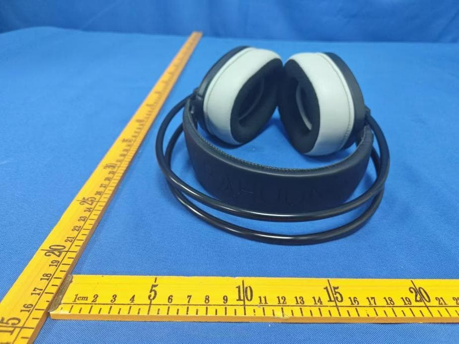
Click to zoom
Application Details
- Equipment Class
- DSS - Part 15 Spread Spectrum Transmitter
- Date of Grant
- Sep 19, 2024
- Application Purpose
- Original Equipment
- Date of Application
- Sep 18, 2024
- Equipment Note
- Wireless headset
- Frequency Range
- 2402.00000000 - 2480.00000000
- Country
- China
Documents & Files
Document Text
Text extracted from the exhibit documents filed with the FCC. Open a document above to read the original.
Users Manual
G5000 11 Usage of Connection Cables: 5.3 Bluetooth C 6国语言:英德日法意西 32 Transmitter LINE-IN Jack Type-C Interface Indicator Light 11. Microphone On (Down Position) Microphone Off (Up Position) Retractable Microphone On/Off Button Product Description Transmitter Parameters English 2.4G/Bluetooth Switch Button On/Off Light/Next Song Button Volume Control Wheel Speaker Diameter Speaker Impedance Battery Capacity Battery TypePolymer Lit hium Battery Charging Time Battery Life Transmission Distance Operating Voltage Charging Voltage Microphone Sensitivity Microphone DirectionalityOmnidirectional Bluetooth Latency 394MS 5 Transmitter Specifications Operating Current Frequency Range Bandwidth Operating VoltageTransmission Power Transmission Distance Receiving Sensitivity 2.4G Latency 30ms Transmitter Device Plug: Compatible with Laptop/PC/PS4/PS5/TV/Switch a)Usage Instructions,Insert the transmitter into the USB port (A-end) or Type-C port (B-end) of your computer for a plug-and-play wireless connection. A.1) Insert the transmitter into the A-end USB port of the computer. The Windows system will automatically connect to the B-end Type-C devices such as phones or laptops, without requiring driver installation or additional software. B.1) Insert the transmitter into the A-end USB port of the computer. The green indicator light on the transmitter will flash. After turning on and pairing the headset, the green light will stay on. On the computer, you can see the "G5000" icon in the lower right corner, indicating the wireless headset device has been successfully installed. For the first use, open the "Sound and Audio Devices Properties" under the "Audio" tab and set it as the default. 6 789 10 B.2)Insert the B-end Type-C transmitter into the Type-C port of a phone or laptop. It will automatically enter pairing mode. The green light will flash rapidly, and once paired, it will stay on. Insert the B-end Type-C transmitter into the phone interface, turn on the wireless headset, and once paired successfully, the green light on the headset will stay on, indicating the plug-and-play wireless connection device has been successfully installed. Re-Pairing 1.After inserting the transmitter into the device, follow steps B.1 and B.2 for connection. 2.Pairing the transmitter and headset: In the off state, hold down the power button for 5 seconds to re-pair. The pairing sound "Pairing" will be heard, the green light will flash rapidly, and then insert the USB receiver for a successful connection. The green light will stay on. BT/2.4G 2.4G /Bluetooth mode /Previous track Power button Pause/Play Connect/Disconnect Answer/End/ Reject call Click Click/ Double click 1. In music play mode, click the power button to pause. 2. In music play mode, click the power button to play. Long press for 3 seconds 2.4G/BT ButtonFunctionOperation Steps 1. Short press for previous track. 2. Long press for 3 seconds to switch to 2.4G mode, green light indicates "Game Mode". 3. Long press for another 3 seconds to switch to Bluetooth mode, blue light indicates "Bluetooth Mode". Next track /Light on/off Click/ Long press for 3 seconds 1. Short press to enter default music mode and play the next track. 2. By default, the headset displays the effect light. Long press for 2 seconds to turn off the effect light, long press again to turn on the effect light. 1. Long press for 3 seconds: Power on 2. Long press for 5 seconds: Power off 3. Long press for 5 seconds: Re-pairing 1. In the power-off state, press and hold the power button for 3 seconds to hear the "Power On" sound, effect light stays on, and the pairing light flashes quickly. 2. In the power-on state, press and hold the power button for 5 seconds to hear the "Power Off" sound, effect light turns off, and the pairing light turns off. 3. For pairing the transmitter and headset: In the power-off state, press and hold the power button for 5 seconds for re-pairing, green light flashes quickly, then plug in the USB receiver to connect successfully, green light stays on. 1. In Bluetooth mode, when there is an incoming call, click the power button to answer. 2. In Bluetooth mode, during a call, click the power button to end the call. 3. In call mode, double click to reject an incoming call (Bluetooth mode). 1. When connecting the headset to the phone, the pairing light shows blue light always on and "Connected" is displayed. 2. When connecting the headset to the phone and then turning off the phone's Bluetooth mode, the prompt sound "Disconnected" is heard, and the pairing blue light flashes quickly. Microphone up/down Turn mic on/off 1. Mic up: Move the mic up to turn off the mic function. 2. Mic down: Move the mic down to turn on the mic function. Using Line-in Connection Cable 1.Device Plug: Compatible with PC (32-bit/64-bit), PS4, PS5, XBOX LINE IN mode, Nintendo Switch, Android, iOS mobile devices, and devices with a 3.5mm audio jack. 2.Line-in Interface Usage Instructions: Insert the Line-in cable to disable the wireless device, turn off the headset effect light, and enter wired headset mode. 3.Microphone usage: When plugged in and Line-in is enabled, the microphone remains on. Volume control USB=Type-C Type-C=3.5 Line-in Type-C charging port Insert charging cable Insert audio cable Using the Line-in interface description: Insert the Line-in cable to turn off wireless devices, turn off headset effect lights, and enter wired headset mode. Charging current: 500mA, red light stays on indicating charging, red light turns off when fully charged. Slide up/down 1. Slide the volume control wheel up to increase the volume to the maximum. 2. Slide the volume control wheel down to decrease the volume to the minimum. Troubleshooting 1.Distortion or Lag in Wireless Headphones: - 1)Check the music source. 2)Disconnect other devices. 3)Reinsert the transmitter and pair again. 2.Multiple Players Lag on PC, but Headset Functions Normally: - 1)Check the playback decoder. 2)Close multiple background players. …
Text truncated - open the document above for the full version.
Attestation Statements
DongguanJinshunxingElectronicsCo.,Ltd (September7,2024) EurofinsElectricalandElectronicTestingNA,Inc. 914WestPatapscoAvenue Baltimore,MD21230 RE:AttestationStatementsPart2.911(d)(5)(i)requestfor (FCCID:2BKNE-G5000) [DongguanJinshunxingElectronicsCo.,Ltd](“theapplicant”)certifiesthatthe equipmentforwhichauthorizationissoughtisnot“covered”equipmentprohibited fromreceivinganequipmentauthorizationpursuanttosection2.903oftheFCCrules. Sincerely, (Applicantsignature) (HanbinChen) DongguanJinshunxingElectronicsCo.,Ltd (September7,2024) EurofinsElectricalandElectronicTestingNA,Inc. 914WestPatapscoAvenue Baltimore,MD21230 RE:AttestationStatementsPart2.911(d)(5)(ii)requestfor (FCCID:2BKNE-G5000) [DongguanJinshunxingElectronicsCo.,Ltd](“theapplicant”)certifiesthat,asofthe dateofthefilingoftheapplication,theapplicantisnotidentifiedontheCoveredListas anentityproducing“covered”equipment. Sincerely, (Applicantsignature) (HanbinChen)
Cover Letter(s)
DongguanJinshunxingElectronicsCo.,Ltd (September7,2024) EurofinsElectricalandElectronicTestingNA,Inc. 914WestPatapscoAvenue Baltimore,MD21230 RE:CONFIDENTIALITYREQUESTFOR(Wirelessheadset/G5000ANDFCCID: 2BKNE-G5000) ToWhomItMayConcern: Thisletterservesasanofficialrequestforconfidentialityundersections0.457and0.459 ofCFR47.Wehaverequestedthatthe(BlockDiagram/Schematics/Operational Description)requiredtobesubmittedwiththisapplicationbepermanentlywithheld frompublicreview. Abovementioneddocumentcontainsdetailedsystemandequipmentdescriptionare consideredasproprietaryinformationinoperationoftheequipment.Thepublic disclosureofabovedocumentsmightbeharmfultoourcompanyandwouldgive competitoranunfairadvantageinthemarket. Incaseofshort-termConfidentiality,theapplicantrequeststheexhibitsselectedabove arewithheldfrompublicviewforaperiodofdaysfromthedateoftheGrantof EquipmentAuthorizationandpriortomarketing. Itisourunderstandingthatallmeasurementtestreports,FCCIDlabelformatand correspondentduringcertificationreviewprocesscannotbegrantedasconfidential documentsandthoseinformationwillbeavailableforpublicreviewoncethegrantof equipmentauthorizationisissued. Pleasecontactmeifthereisanyinformationyoumayneed. Sincerely, Mustbesignedbytheapplicantcontactcitedastechnicalornon-technicalcontactonthe 731formprovidedtoEurofinsMETLabs,orbytheauthorizedagentifanappropriate authorizedagentletterhasbeenprovided.Letterssignedbytheapplicantshouldbe placedonapplicantletterhead.
Cover Letter(s)
DongguanJinshunxingElectronicsCo.,Ltd (September7,2024) EurofinsElectricalandElectronicTestingNA,Inc. 914WestPatapscoAvenue Baltimore,MD21230 RE:LETTEROFAGENTAUTHORIZATION ToWhomItMayConcern: We,theundersigned,herebyauthorize(PreciseTesting&CertificationCo.,Ltd.)toactonour behalfinallmattersrelatingtoapplicationforequipmentauthorization,includingthesigningof alldocumentsrelatingtothesematters. Wealsoherebycertifythatnopartytotheapplicationauthorizedhereunderissubjecttothe denialofbenefits,includingFCCbenefits,pursuanttoSection5301oftheAnti-DrugAbuseAct of1988,21U.S.C.853(a). Thisagreementexpiresoneyearfromthecurrentdate. Sincerely, Mustbesignedbytheapplicantcontactcitedastechnicalornon-technicalcontactonthe 731formprovidedtoEurofinsMETLabs,orbytheauthorizedagentifanappropriate authorizedagentletterhasbeenprovided.Letterssignedbytheapplicantshouldbe placedonapplicantletterhead.
External Photos
FCCID:2BKNE-G5000 FCCID:2BKNE-G5000 FCCID:2BKNE-G5000 FCCID:2BKNE-G5000
Internal Photos
FCCID:2BKNE-G5000 FCCID:2BKNE-G5000 FCCID:2BKNE-G5000 FCCID:2BKNE-G5000 FCCID:2BKNE-G5000
RF Exposure Info
Page1of2 RFEXPOSUREEVALUATION FCCID:2BKNE-G5000 ProductName: Wirelessheadset ModelName: G5000 BluetoothVersion:BTBDR+EDR+BLE Operatingfrequency:2402-2480MHz NumbersofChannel: 79channelsforBDR+EDR 40channelsforBLE AntennaType:Ceramicantenna AntennaGain: 1.24dBi TypeofModulation: GFSK,Π/4-DQPSK,8DPSKForDSS GFSKforBLE Powersupply: Input:DC5V1A Li-ionBattery:240603 RatedVoltage:3.7V RatedCapacity:1000mAh HardwareVersion:N/A SoftwareVersion: K68_BBH881-JSX-G5000_AC7018M8_8M_HW0.00_SW0.0.0_(G5000)_C5 01-04CF55B5_20240703_ear Page2of2 StandardRequirement Accordingto§15.247(i)and§1.1307b(1),systemsoperatingundertheprovisionsofthis sectionshallbeoperatedinamannerthatensuresthatthepublicisnotexposedtoradio frequencyenergylevelsinexcessoftheCommission’sguidelines.SeeKDB447498D01 GeneralRFExposureGuidancev06,section4.3.1. The1-gand10-gSARtestexclusionthresholdsfor100MHzto6GHzattestseparation distances≤50mmaredeterminedby: [(max.powerofchannel,includingtune-uptolerance,mW)/(min.testseparationdistance, mm)]*[√f(GHz)]≤3.0for1-gSARand≤7.5for10-gSARextremitySAR,where f(GHz)istheRFchanneltransmitfrequencyinGHz PoweranddistanceareroundedtothenearestmWandmmbeforecalculation Theresultisroundedtoonedecimalplaceforcomparison. Thetestexclusionsareapplicableonlywhentheminimumtestseparationdistanceis≤ 50mmandfortransmissionfrequenciesbetween100MHzand6GHz.Whentheminimumtest separationdistanceis<5mm,adistanceof5mmisappliedtodetermineSARtestexclusion. RoutineSARevaluationreferstothatspecificallyrequiredby§2.1093,usingmeasurements orcomputersimulation.WhenroutineSARevaluationisnotrequired,portabletransmitters withoutputpowergreaterthantheapplicablelowthresholdrequireSARevaluationtoquality forTCBapproval. Channel (MHz) Maximum output power (dBm) Tuneup tolerance (dBm) MaxTuneUp Power(mW) Distance (mm) Calculation results Limit Operating Mode 2480-1.06 -1.06±1 0.98627950.3106393BT 2480-1.99-1.99±10.79615950.2507593BLE AccordingtoKDB447498,nostand-alonerequiredforBTantenna,andnosimultaneousSAR measurementisrequired. Signature SimonPu Manager Date:2024-08-23
Test Report
2.4GHz 3216 Chip Antenna: HT-3216-C02 A- WLAN. 802.1 1 b/g, Bluetooth, WLAN, etc... 压 SMD, high reliability, ultra Impact, Omni-di「ectional... Part number Information F 245 C 02 HT 3216 ( A) (B) (C)(D)(E)(F) (A)Product Type Chip Antenna (B) Size Code 3.2x1.6mm(士0.2mm) (C) Material High K material (D) Frequency 2.4 ~ 2.5GHz (E) Feeding mode PIFA & Single Feeding (F) Antenna type Type = 02 Electrical S,eecification Working Frequency Range 2400 ~2500 MHz Bandwidth 120 MHz (Min.) Peak Gain 1.15 dBi ( Typ.) Impedance 500hm ` .、 \ Return loss 10 dB ( Min) 二 Polarization Linear 7/ / Azimuth Beamwidth Omni-directional Operation Temperature( ° C) ` -40 ~85 ° C \ Resistance to Soldering Heats \ J 10sec. (@ 280 ° C) Termination Ni / Au (Leadless) The specification is defined on EVB Dimension and Terminal Configuration S记e To户—L-尸 Dimension (mm) (1� 勹勹 L 3.20士0.20 w 1.60士0.20 T 0.45士0.20 Bottom No. 1 2 让 Terminal Name Feeding/GNG GND/Feeding RoHS lead-fre已comp|iant 2.4GHz 3216 Chip Antenna: HT-3216-C02 Evaluation Board Reference PCB Dimension : : . ... . .. . .』 f. : : : : : : t · · · · ···:· : : : : 嘈, . 枷· ..... . ..`嗓 . 挚... . ..... . ..... . ...易....'. . ...息 . ...潭 · 参. 争 . · . .. 眷 . . 嘈 . . . 噜 . · . 晕 .. · ..... . .... . . ..... . ..... . ......... . .... . .... • ... . .. ..... .曹夸..... . . . • . 参瘟 . . .. • 参 . . . . . . . . . . .. . 羲 . . . . 瘤蠡 .. • • . . `. . . • • . .. • • . . . . Electrical Characteristics 1 ... Return Loss & Radiation Return Loss ►illJ S22 Log M丐10.00dB/Roi O.OOOdB [Fl] SO.DO 40.00 30.00 20.00 10.00 0.000 -10.00 -20.00 -30.00 -40.00 I -so.oo 历又m1<lHz Radiation 270 90 180 —XY — xz Y Z l Efficiency Peak Gain Directivity ►1 2.400000000 GHz -10.502哗 2 2.450000000 GHz -30.620 d8 3 2.部XlOOOOGHz -11.472哗 270 90 180 — 双 — xz — Y Zl 2400MHz 2450MHz 82.52% 85.26% 1.15 dBi 1.24 dBi 1.89 dBi 1.97 dBi 270 o 2500MHz 90 180 —双 - xz-yz l 2500MHz 83.01% 1.19 dBi 1.91 dBi 2450 2500 亿 Unit :mm S11 (dB) -10.50 -30.62 -11.47 : :玄�: : �l� f」+ 2.4GHz 3216 Chip Antenna: HT-3216-C02 亿 Ta.el 出 电ecifications Reel and Taping Specification Reel Specification 产一 2勹 罕 门勹 7.x8mm TYPE SIZE A B C D 3216 7 ” 51</Reel I 9.0 士 0.5 60 士 2 13.5士0.5 178士2 Tapping Specification 产 二 三 』 」汇山 上』 Paper Carrier Packagi_ng | Type A B w E F G H T ,p D p Pap e「Ty p e l 3216 I 1.90士0.2013.50士0.2018.0土0.20I 1.75土010| 3 5士o.osI 4.o士0.10I 2.0土o.o5I o.75士0.101 1 5 0土0.10 1 4.0士0.1 2.4GHz 3216 Chip Antenna: HT-3216-C02 亿 _ Test Item Procedure Requirements Ceramic Type Remark (Reference) Electrical Fulfill the electrical User Spec. Characterization specification Thermal 1. Preconditioning:No Visible Damage. MIL-STD-202 Shock 50土1o·c / 1 hr, then keep for 24士1 hrs at room temp Fulfill the electrical 107 2. In仆ial measure: Spec· refer Initial spec specification 3. Rapid change of temperature test: .3o·c to +as·c, 100 cycles; 15 minutes at Lower category temperature; 15 minutes at Upper category temperature Temperature 1. Initial measure: Spec refer Initial spec No Visible Damage. JESD22 Cycling 2. 100 Cycles (-3o·c to +as·c), Soak Mode=1 (2 Cycle/hours) Fulfill the electrical JA104 3. Measurement at 24土2Hoursafter test condition specification High Temperature 1. Initial measure: Spec refer Initial spec No Visible Damage MIL-STD-202 A` Exposure 2. Unpowered, 500hours @T=+85"C Fulfill the electrical 108 3. Measurement at 24士2 hours aftertest ·,. specification `` Low Temperature 1. Initial measure: Spec refer Initial spec No Visible Damage MIL-STD-202 Storage 2. Unpowered 500hours @ T= -30'CFulfill the electrical 108 3. Measu「ementat 24士2 hours aftertest ;, , , specification .· ,.. Solderability Dipping method: ·, 俨 The solder should cove「IEC 60384-21/22 (SMD Bottom Side) a. Temperature 235士5 ° C \' L -� •. 、 女 , over 95% of the critical 4.10 b. Dipping time 3士O5s 1. , � � area of bottom side. Soldering Heat Preheating temperature: 150土10 ° C '. -气 I 、� No Visible Damage. IEC 60384-21/22 Resistance Preheating time: 1-2 min. 4.10 (RSH) Solder temperature 260士5 ° C ;、 Dipping time: 5土o5s 4' Vibration 5g's for 20 min 12 cycles each of 3 orientations No Visible Damage. MIL-STD-202 Note· Use 8"X5" PCB 031" thick 7 secure points on, one long Method 204 side and 2 secu「epoints at co「nersof opposite sides Parts mounted within 2" from any secure point Test f「om 10-2000 Hz Mechanical Three shocks in each di「ectionshall be applied along the th「eeNo Visible Damage. MIL-STD-202 Shock mutually perpendicular axes of the test specimen (18 shocks) Method 213 Peak value 1,500g's Duration: O 5ms Velocity change. 15 4 fVs Waveform: Half-sine Humidity 1. Humidity 85% RH, Temperature:85士2 ° c No Visible Damage MIL-STD-202 Bias 2. Time 500士24hours Fulfill the electrical Method 106 3. Measurement at 24士2hrs after test conditionspecification 2.4GHz 3216 Chip Antenna: HT-3216-C02 亿 Board Flex (SMD) 1. Mounting method: J No Visible Damage AEC-Q200 005 Adhesion Physical Dimension IR-Reflow. PCB Size (L:1 00 x W:40 x T:1.6mm) 2. Apply the load in direction of the arrow until bending reaches 2mm. Fo「ceof 1.8Kg fo「60seconds 1霾dlu.0,Smm WICM .Ub.行械 ' . 尸."tool \ 4 中.. ,伈IC. Any applicable method using x1 O magnification, micrometers, calipers, gauges, contour projectors, or other measuring equipment, capable of determining the actual specimen dimensions. Revision Histo 以 Revision 1 Date 2019/10/01 Content New Datasheet NoVislbIe Damage I AEC-Q200 Magnification of 20X or I 006 greater may be employed for inspection of the mechanical integrity of the device body tenninals and body/terminal junction In accordance with specification JESD22 JB100
Test Report
ReportNo.:PTC24080509102E-FC01 Page 1 of 88 FCCTESTREPORT FCCID:2BKNE-G5000 Product:Wirelessheadset ModelName:G5000 Brand:N/A ReportNo.:PTC24080509102E-FC01 Preparedfor DongguanJinshunxingElectronicsCo.,Ltd Building2,No.11JinhuRoadSecondStreet,Liwu,QiaotouTown,DongguanCity Preparedby PreciseTesting&CertificationCo.,Ltd. Building1,No.6,TongxinRoad,DongchengStreet,Dongguan,Guangdong,China ReportNo.:PTC24080509102E-FC01 Page 2 of 88 1TESTRESULTCERTIFICATION Applicant’sname:DongguanJinshunxingElectronicsCo.,Ltd Address: Building2,No.11JinhuRoadSecondStreet,Liwu,QiaotouTown, DongguanCity Manufacture'sname:DongguanJinshunxingElectronicsCo.,Ltd Address: Building2,No.11JinhuRoadSecondStreet,Liwu,QiaotouTown, DongguanCity Productname:Wirelessheadset Modelname:G5000 Standards:FCCCFR47Part15Section15.247 Testprocedure:ANSIC63.10:2013 TestDate:Aug.10,2024toAug.22,2024 DateofIssue:Aug.22,2024 TestResult:Pass ThisdevicedescribedabovehasbeentestedbyPTC,andthetestresultsshowthatthe equipmentundertest(EUT)isincompliancewiththeFCCrequirements.Anditisapplicable onlytothetestedsampleidentifiedinthereport. Thisreportshallnotbereproducedexceptinfull,withoutthewrittenapprovalofPTC,this documentmaybealteredorrevisedbyPTC,personalonly,andshallbenotedintherevision ofthedocument. TestEngineer: Jackzhou/Engineer TechnicalManager: SimonPu/Manager ReportNo.:PTC24080509102E-FC01 Page 3 of 88 Contents Page 1TESTRESULTCERTIFICATION...............................................................................................................................2 2TESTSUMMARY..........................................................................................................................................................5 3TESTFACILITY.............................................................................................................................................................5 4GENERALINFORMATION..........................................................................................................................................6 4.1GENERALDESCRIPTIONOFE.U.T.....................................................................................................................6 4.2TESTMODE.........................................................................................................................................................7 5EQUIPMENTDURINGTEST......................................................................................................................................9 5.1EQUIPMENTSLIST...............................................................................................................................................9 5.2MEASUREMENTUNCERTAINTY.........................................................................................................................11 5.3DESCRIPTIONOFSUPPORTUNITS...................................................................................................................12 6CONDUCTEDEMISSION..........................................................................................................................................13 6.1E.U.T.OPERATION............................................................................................................................................13 6.2EUTSETUP.......................................................................................................................................................13 6.3TESTSET-UP(BLOCKDIAGRAMOFCONFIGURATION).................................................................................14 6.4MEASUREMENTPROCEDURE:...........................................................................................................................14 6.5CONDUCTEDEMISSIONLIMIT...........................................................................................................................14 6.6MEASUREMENTDESCRIPTION..........................................................................................................................14 6.7CONDUCTEDEMISSIONTESTRESULT.............................................................................................................14 7RADIATEDSPURIOUSEMISSIONS......................................................................................................................17 7.1EUTOPERATION...............................................................................................................................................17 7.2TESTSETUP......................................................................................................................................................18 7.3SPECTRUMANALYZERSETUP..........................................................................................................................19 7.4TESTPROCEDURE.............................................................................................................................................20 7.5SUMMARYOFTESTRESULTS...........................................................................................................................21 8MAXIMUMPEAKOUTPUTPOWERTEST............................................................................................................28 8.1TESTSTANDARDANDLIMIT..............................................................................................................................28 8.2TESTSETUP......................................................................................................................................................28 8.3TESTPROCEDURE.............................................................................................................................................28 8.4TESTDATA.........................................................................................................................................................29 ReportNo.:PTC24080509102E-FC01 Page 4 of 88 920DBOCCUPYBANDWIDTHTEST.......................................…
Text truncated - open the document above for the full version.
Test Setup Photos
FCCID:2BKNE-G5000 ConductedEmissions RadiatedEmissions From30MHz-1000MHz FCCID:2BKNE-G5000 TestfrequencyfromAbove1GHz
Contact Information
Applicant
Hanbin Chen(Manager)
Test Firm
Precise Testing & Certification Co., LTD.Chris Du
[email protected]+86-769-38808222
Technical Specifications
| # | Rule Parts | Frequency Range | Power Output |
|---|---|---|---|
| 1 | 15C | 2.40 GHz - 2.48 GHz | 783.00 µW |