2BLL9-OBDCHECKEWENET WiFi Adapter
SPIRESH TECH INC.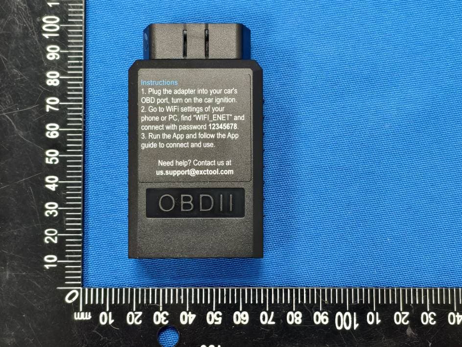
Click to zoom
Application Details
- Equipment Class
- DTS - Digital Transmission System
- Date of Grant
- May 09, 2026
- Application Purpose
- Original Equipment
- Equipment Note
- ENET WiFi Adapter
- Frequency Range
- 2412.00000000 - 2462.00000000
- Company
- SPIRESH TECH INC.
- Country
- Canada
Documents & Files
Document Text
Text extracted from the exhibit documents filed with the FCC. Open a document above to read the original.
Users Manual
OBDCheck EW User Instruction Connection Steps 1. Plug the adapter into your car’s OBD-II port. Ensure it is securely inserted. 2. Turn on car ignition. 3. Open your phone’s WiFi settings. Wait for “WiFi_ENET” to show up and join the network by password 12345678. 4. Open your App, select ENET WiFi adapter or make the proper settings and connect. Note: Be sure to grant the necessary App permissions including Local Network (iOS), Nearby Devices (Android). For detailed in-App usage instructions, visit the App’s official website. Verbindung herstellen 1. Stecken Sie den Adapter in den OBD-II-Anschluss Ihres Fahrzeugs. Achten Sie darauf, dass er fest sitzt. 2. Zündung einschalten. 3. Öffnen Sie die WLAN-Einstellungen Ihres Smartphones. Warten Sie, bis „WiFi_ENET“ angezeigt wird, und verbinden Sie sich mit dem Passwort 12345678. 4. Öffnen Sie Ihre App, wählen Sie den ENET WiFi-Adapter oder nehmen Sie die entsprechenden Einstellungen vor und verbinden Sie. Hinweis: Erteilen Sie die erforderlichen App-Berechtigungen, einschließlich Lokales Netzwerk (iOS) und Geräte in der Nähe (Android). Für detaillierte Nutzungshinweise besuchen Sie bitte die offizielle Website der App. Connexion 1. Branchez l’adaptateur sur le port OBD-II de votre véhicule. Assurez-vous qu’il est bien inséré. 2. Mettez le contact de la voiture. 3. Ouvrez les paramètres WiFi de votre téléphone. Attendez que « WiFi_ENET » apparaisse et connectez-vous au réseau avec le mot de passe 12345678. 4. Ouvrez votre application, sélectionnez l’adaptateur ENET WiFi ou configurez les paramètres appropriés et connectez-vous. Remarque : Accordez les autorisations nécessaires à l’application, notamment Réseau local (iOS) et Appareils à proximité (Android). Pour des instructions détaillées, consultez le site officiel de l’application. Connessione 1. Inserire l’adattatore nella porta OBD-II della vettura. Assicurarsi che sia ben inserito. 2. Accendere il quadro della macchina. 3. Aprire le impostazioni WiFi del telefono. Attendere che appaia “WiFi_ENET” e connettersi alla rete usando la password 12345678. 4. Aprire l’App, selezionare l’adattatore ENET WiFi o impostare correttamente le opzioni e connettersi. Nota: Concedere le autorizzazioni necessarie all’App, inclusi Rete locale (iOS) e Dispositivi nelle vicinanze (Android). Per istruzioni dettagliate, visitare il sito ufficiale dell’App. Conexión 1. Conecte el adaptador al puerto OBD-II de su vehículo. Asegúrese de que esté bien insertado. 2. Encienda el contacto del coche. 3. Abra los ajustes de WiFi de su teléfono. Espere a que aparezca “WiFi_ENET” y únase a la red usando la contraseña 12345678. 4. Abra su App, seleccione el adaptador ENET WiFi o configure los ajustes adecuados y conéctese. Nota: Conceda los permisos necesarios a la App, incluyendo Red local (iOS) y Dispositivos cercanos (Android). Para instrucciones detalladas, visite la página oficial de la App. 1. OBD-II 2. ON 3. WiFi WiFi_ENET 12345678 4. ENET WiFi :iOS :Android Compatible Applications Windows: ISTA+, E-SYS Android: BimmerCode, Bimmerlink, Bootmod3, xDelete, xHP Flashtool, Deep OBD, MHD Flasher, BimmerGeeks ProTool iOS: BimmerCode, Bimmerlink, DITUPA, Bootmod3, xDelete, xHP Flashtool, MHD Flasher, MKFlasher May also work with other software or Apps that support a standard ENET WiFi adapter. Special Notes 1. Compatible with BMW & Mini F series, G and I series. E series not supported. 2. Each App or software has its own vehicle compatibility. Please check on their website to check if your specific model/year is supported, and what functions are supported. 3. For G-Series cars, the diagnostic mode has to be activated additionally (press the start button in the car three times in quick succession without pushing the brake or clutch pedal). 4. Unplug the adapter after use. Don’t leave it plugged for days, as it may drain your car’s battery. Support and Warranty Customer support: [email protected]. All Veepeak products are covered by one-year replacement warranty against defect from the date of purchase. Valid purchase proof required. Disclaimer Features and functions are offered and achieved through third-party Applications. We are not responsible for any warranty voided or damaged caused by using these Applications. Software names, brands, vehicle makes/models and other trademarks featured or referred to within this user manual are the property of their respective trademark holders. Use of them does not imply any affiliation with or endorsement by them. - 1 - - 5 -- 6 -- 7 -- 8 - - 2 -- 3 -- 4 - - - 9 Warning Statement This device complies with part 15 of the FCC Rules. Operation is subject to the following two conditions: (1) This device may not cause harmful interference, and (2) this device must accept any interference received, including interference that may cause undesired operation. Any Changes or modifications not expressly approved by the party responsible for compliance could void the user's authority to operate the equipment. Note: This equipment has been tested and found to comply with the limits for a Class B digital device, pursuant to part 15 of the FCC Rules. These limits are designed to provide reasonable protection against harmful interference in a residential installation. This equipment generates uses and can radiate radio frequency energy and, if not installed and used in accordance with the instructions, may cause harmful interference to radio communications. However, there is no guarantee that interference will not occur in a particular installation. If this equipment does cause harmful interference to radio or television reception, which can be determined by turning the equipment off and on, the user is encouraged to try to correct the interference by one or more of the following measures: -Reorient or relocate the receiving antenna. -Increase the separation between the equipment and receiver. -Connect the equipment into an outlet on a circuit different from that to which the receiver is connected. -…
Text truncated - open the document above for the full version.
Attestation Statements
1/1 US Agent for Service of Process LETTER OF ATTESTATION TO: Office of Engineering Technology Federal Communications Commission 7435 Oakland Mills Road Columbia, MD 21046 US Agent for Service of Process: Company Name: GLOCERTS TECHNOLOGY INC FRN: 0036339737 Contact Name: Huiying Fan Address: 19784 SUNKISSED RIDGE DR, RIVERSIDE, CA 92507 Telephone (626) 588-8039 Email: [email protected] This letter is to confirm that the US Agent for Service of Process accepts responsibility to act as a local representative on behalf of SPIRESH TECH INC. The US Agent for Service of Process is aware of and agrees to comply with the requirements outlined in the FCC Equipment Authorization Program, Report and Order FCC 22-84, and clause § 2.911. Applicant: Company name: SPIRESH TECH INC. FRN: 0036105765 Grantee code: 2BLL9 FCC ID: 2BLL9-OBDCHECKEW Contact Name: Bert Wan Address: 222 QUEEN STREET, 1000, OTTAWA, ON K1P 5V9, Canada Telephone No: +1 6137993721 Fax No: +1 6137993721 Email: [email protected] The Applicant is aware of and agrees to comply with the requirements outlined in the FCC Equipment Authorization Program, Report and Order FCC 22-84, and clause § 2.911. Date: 2026/04/27 Applicant’s Name: Bert Wan US Agent for Service of Process’s Name: Huiying Fan Title: General Manager Title: Director Signature: Signature:
Attestation Statements
(SPIRESH TECH INC.) (2026-04-27) Eurofins Electrical and Electronic Testing NA, Inc. 914 West Patapsco Avenue Baltimore, MD 21230 RE: Attestation Statements Part 2.911(d)(5)(i) request for (FCC ID:2BLL9-OBDCHECKEW) [SPIRESH TECH INC.] (“the applicant”) certifies that the equipment for which authorization is sought is not “covered” equipment prohibited from receiving an equipment authorization pursuant to section 2.903 of the FCC rules. We also certify that, as of the date of the filing of the application, the equipment does not utilize cyber-security or anti-virus software from Kaspersky Lab, Inc, or any of its successors and assignees, which is also on the “covered list”. Sincerely, (Applicant signature): (Applicant printed name): Bert Wan (SPIRESH TECH INC.) (2026-04-27) Eurofins Electrical and Electronic Testing NA, Inc. 914 West Patapsco Avenue Baltimore, MD 21230 RE: Attestation Statements Part 2.911(d)(5)(ii) request for (FCC ID:2BLL9-OBDCHECKEW) [SPIRESH TECH INC.] (“the applicant”) certifies that, as of the date of the filing of the application, the applicant is not identified on the Covered List as an entity producing “covered” equipment. Sincerely, (Applicant signature): (Applicant printed name): Bert Wan
Cover Letter(s)
SPIRESH TECH INC. Agent Authorization Letter (2026/04/27) Eurofins Electrical and Electronic Testing NA, Inc. 914 West Patapsco Avenue Baltimore, MD 21230 RE: LETTER OF AGENT AUTHORIZATION To Whom It May Concern: We, the undersigned, hereby authorize (MAXLAB Testing Co.,Ltd.) to act on our behalf in all matters relating to application for equipment authorization, including the signing of all documents relating to these matters. We also hereby certify that no party to the application authorized hereunder is subject to the denial of benefits, including FCC benefits, pursuant to Section 5301 of the Anti-Drug Abuse Act of 1988, 21 U.S.C.853(a). This agreement expires one year from the current date. Sincerely, Client’s signature : Client’s name / title : Bert Wan / General Manager Contact information / address: 222 QUEEN STREET, 1000, OTTAWA, ON K1P 5V9, Canada
Cover Letter(s)
SPIRESH TECH INC. Long Term Confidentiality Request Letter (2026-04-27) Eurofins Electrical and Electronic Testing NA, Inc. 914 West Patapsco Avenue Baltimore, MD 21230 RE: CONFIDENTIALITY REQUEST FOR(ENET WiFi Adapter / OBDCheck EW / FCC ID:2BLL9-OBDCHECKEW) To Whom It May Concern: - This letter serves as an official request for confidentiality under sections 0.457 and 0.459 of CFR 47. We have requested that the - - Block Diagram - Schematics - Operational Description required to be submitted with this application be permanently withheld from public review. The above materials contain trade secrets and proprietary information not customarily released to the public. The public disclosure of these materials may be harmful to the applicant and provide unjustified benefits to its competitors. Please contact me if there is any information you may need. Sincerely, Client’s signature : Client’s name / title : Bert Wan / General Manager Contact information / address: 222 QUEEN STREET, 1000, OTTAWA, ON K1P 5V9, Canada
ID Label/Location Info
4cm Model: OBDCheck EW FCC ID: 2BLL9-OBDCHECKEW This device complies with part 15 of the FCC Rules. Operation is subject to the following two conditions: (1) This device may not cause harmful interference, and (2)this device must accept any interference received, including interference that may causeundesired operation. Label Location 1cm
Internal Photos
TX ANT
RF Exposure Info
RF EXPOSURE REPORT for SPIRESH TECH INC. Model Number: OBDCheck EW FCC ID: 2BLL9-OBDCHECKEW Prepared for : SPIRESH TECH INC. Address : 222 QUEEN STREET, 1000, OTTAWA, ON K1P 5V9, Canada Prepared by : MAXLAB Testing Co.,Ltd. Address : 1/F, Building B, Xinshidai GR Park,Shiyan Street, Bao'an District, Shenzhen,Guangdong, 518052, People’s Republic of China 1. RF EXPOSURE EVALUATION Test Result of RF Exposure Evaluation According to the KDB-447498 D01 V06, FCC 47CFR§2.1093 the following RF exposure evaluation shall to demonstrate RF exposure compliance. [(max. power of channel, including tune-up tolerance, mW) / (min. test separation distance,mm)] * [√f(GHz)] 2.4G Antenna port Target power W/ tolerance (dBm) Max tune up power tolerance (dBm) Maximum Conducted Output Power (mW) Antenna Gain (dBi) Separation distance mm RF exposure 802.11b ANT1 1±1.0 2 1.59 1.99(3dBi) 5 0.49 802.11g ANT1 1±1.0 2 1.59 1.99(3dBi) 5 0.49 802.11n 20MHz ANT1 1±1.0 2 1.59 1.99(3dBi) 5 0.49 802.11n 40MHz ANT1 1±1.0 2 1.59 1.99(3dBi) 5 0.49 The Max RF exposure is 0.49. Threshold at which no SAR required is≤ 3.0 for 1-g SAR, Separation distance is 5mm. Conclusion: So no SAR is required.
Test Report
承认书项目表 内 容 页数 页码 NO. ( Number ( Page ( Contents ) ofPage ) Code ) 1 承认书封面 (Spec Cover) 11 2 承认书项目表(Spec Item) 12 3 工程成品图 ( Drawing ) 13 4 电性测试报告(Test Reports) 14 5 S 参数测试( S Parameter ) 15 6 增益测试 (Gain Test) 16 7 8 9 10 --- 1 1 --- 12--- 电性测试报告 T estReports ElectricalProperties Frequency2.4 - 2.5 GHz Impedance50 0hm Nominal V.S.W.R<= 2.0 Max Return Loss-10 dB Max RadiationOmni-directional Gain (Peak)3.0dBi Cable Loss3.2 dB / m Max @ 2450 MHz PolarizationLinear, Vertical Admitted Power1 W Connectoripex PhysicalProperties A ntenna MaterialCU Cable TypeO.D. 1.13mm // 150 mm Operating Temp.-10 ~ +60 ̊C Storage Temp. -10 ~ +70 ̊C Cable ColorBlack Tel:86-0769-33691210 Fax:86-0769-82381572 SIGN DATE DESCRIPTION APPROVER R-CB-113B NB080 CI-113 No. CU Coaxial Cable Connector Name ĭ4.4 *24.5mm SHOWA-O.D. 1.13mm Black Mini Connector Material Q ty Part Number TITLE: 2.4GHz Antenna PART NO.: TG-2505-IPEX 1-10CM APPROVED BY DWG NAME: NB080-13B-IX150.DWG DESIDNED BY UNITS: mm Tolerance CHECKED BY SCALE: 1/1 REVISION: A jeff 2014-02-26 2014-02-26 leon 2014-02-26 YD X.X ±0.20X.XX ±0.10X° ±3° ✝㕙㇑˅ TG-2505-IPEX 1-15CMTG-2505-IPEX 1-15CM S 参数测试 SParameterTest AgilentE5071C ÿÿÿÿÿÿÿÿÿÿÿÿÿ 增益测试 GainTest Antenna Radiation Pattern VS Gain
Test Report
Page 1 of 34 MAXLAB Testing Co.,Ltd. Report No.: MAX26041513P01-R01 FCC PART 15 SUBPART C TEST REPORT FCC PART 15.247 Report Reference No. ..................... : MAX26041513P01-R01 FCC ID............................................. : 2BLL9-OBDCHECKEW Compiled by ( position+printed name+signature) . : Engineer/ Cindy Zheng Supervised by ( position+printed name+signature) . : Manager/Haley Wen Approved by ( position+printed name+signature) . : RF Manager/ Vivian Jiang Date of issue .................................... : April 23, 2026 Testing Laboratory Name .............. : MAXLAB Testing Co.,Ltd. Address ............................................ : 1/F, Building B, Xinshidai GR Park,Shiyan Street, Bao'an District, Shenzhen,Guangdong, 518052, People’s Republic of China Applicant’s name ............................ : SPIRESH TECH INC. Address ............................................ : 222 QUEEN STREET, 1000, OTTAWA, ON K1P 5V9, Canada Test specification ........................... : Standard ........................................... : FCC Part 15.247 KDB558074 D01 15.247 Meas Guidance v05r02 ANSI C63.10:2020 MAXLAB Testing Co.,Ltd. All rights reserved. This publication may be reproduced in whole or in part for non-commercial purposes as long as the MAXLAB Testing Co.,Ltd.is acknowledged as copyright owner and source of the material. MAXLAB Testing Co.,Ltd.takes no responsibility for and will not assume liability for damages resulting from the reader's interpretation of the reproduced material due to its placement and context. Test item description ..................... : ENET WiFi Adapter Trade Mark ....................................... : VEEPEAK Manufacturer .................................... : Shenzhen Chaoyue Technology Development Co., Ltd. Model/Type reference ...................... : OBDCheck EW Listed Models .................................. : N/A Modulation Type ............................... : DSSS/ OFDM Operation Frequency ........................ : From 2412 - 2462MHz Rating ............................................... : DC9-16V Result ............................................... : PASS MAXLAB Testing Co.,Ltd. Report No.: MAX26041513P01-R01 Page 2 of 37 TEST REPORT Equipment under Test : ENET WiFi Adapter Model /Type : OBDCheck EW Series Model No. N/A Model Declaration : N/A Applicant : SPIRESH TECH INC. Address : 222 QUEEN STREET, 1000, OTTAWA, ON K1P 5V9, Canada Manufacturer : Shenzhen Chaoyue Technology Development Co., Ltd. Address : Building C, Zhiyun Industrial Park, No. 13 Huaxing Road, Tongsheng Community, Dalang Street, Longhua District, Shenzhen Guangdong 518000 China (Peoples Republic Of) Test Result: PASS The test report merely corresponds to the test sample. It is not permitted to copy extracts of these test result without the written permission of the test laboratory. MAXLAB Testing Co.,Ltd. Report No.: MAX26041513P01-R01 Page 3 of 37 Contents 1 T E S T S T A N D AR D S . . . . . . . . . . . . . . . . . . . . . . . . . . . . . . . . . . . . . . . . . . . . . . . . . . . . . . . . . . . . . . . . . . . . . . . . 4 2 S U M M AR Y . . . . . . . . . . . . . . . . . . . . . . . . . . . . . . . . . . . . . . . . . . . . . . . . . . . . . . . . . . . . . . . . . . . . . . . . . . . . . . . . . . . 5 2.1 General Remarks .......................................................................................................................................... 5 2.2 Product Description ..................................................................................................................................... 5 2.3 Equipment Under Test ................................................................................................................................. 6 2.4 Short description of the Equipment under Test (EUT) ............................................................................. 6 2.5 EUT operation mode .................................................................................................................................... 7 2.6 Block Diagram of Test Setup ...................................................................................................................... 7 2.7 Related Submittal(s) / Grant (s) ................................................................................................................... 7 2.8 Modifications ................................................................................................................................................ 7 3 T E S T E N V I R O N M E N T . . . . . . . . . . . . . . . . . . . . . . . . . . . . . . . . . . . . . . . . . . . . . . . . . . . . . . . . . . . . . . . . . . . . 8 3.1 Address of the test laboratory .................................................................................................................... 8 3.2 Test Facility ................................................................................................................................................... 8 3.3 Environmental conditions ........................................................................................................................... 8 3.4 Test Description ........................................................................................................................................... 9 3.5 Statement of the measurement uncertainty .............................................................................................. 9 3.6 Equipments Used during the Test ............................................................................................................ 10 4 T E S T C O N D I T I O N S A N D R E S U L T S . . . . . . . . . . . . . . . . . . . . . . . . . . . . . . . . . . . . . . . . . . . . . . . . . . 1 2 4.1 AC Power Conducted Emission ................................................................................................................ 12 4.2 Radiated Emission ..................................…
Text truncated - open the document above for the full version.
Test Report
MAXLAB Testing Co.,Ltd. Report No.: MAX26041513P01-R01 Page 26 of 37 4.6 Out-of-band Emissions Limit In any 100 kHz bandwidth outside the frequency band in which the spread spectrum or digitally modulated intentional radiator is operating, the radio frequency power that is produced by the intentional radiator shall be at least 20 dB below that in the 100 kHz bandwidth within the band that contains the highest level of the desired power, based on either an RF con-ducted or a radiated measurement, pro-vided the transmitter demonstrates compliance with the peak conducted power limits. If the transmitter com-plies with the conducted power limits based on the use of RMS averaging over a time interval, as permitted under paragraph (b)(3) of this section, the attenuation required under this paragraph shall be 30 dB instead of 20 dB. Attenuation below the general limits specified in §15.209(a) is not required. Test Procedure Connect the transmitter output to spectrum analyzer using a low loss RF cable, and set the spectrum analyzer to RBW=100 kHz, VBW= 300 kHz, peak detector , and max hold. Measurements utilizing these setting are made of the in-band reference level, bandedge and out-of-band emissions. Test Configuration EUT SPECTRUM ANALYZER Test Results Remark: The measurement frequency range is from 30MHz to the 10th harmonic of the fundamental frequency. The lowest, middle and highest channels are tested to verify the spurious emissions and bandage measurement data. And record the worst data in the report. Mode Frequency (MHz) Max Value (dBc) Limit (dBc) Verdict b 2412 -34.36 -20 Pass b 2437 -34.15 -20 Pass b 2462 -33.06 -20 Pass g 2412 -25.91 -20 Pass g 2437 -26.53 -20 Pass g 2462 -26.31 -20 Pass n20 2412 -23.58 -20 Pass n20 2437 -24.17 -20 Pass n20 2462 -25.99 -20 Pass n40 2422 -23.22 -20 Pass n40 2437 -22.33 -20 Pass n40 2452 -23.40 -20 Pass Test plot as follows: MAXLAB Testing Co.,Ltd. Report No.: MAX26041513P01-R01 Page 27 of 37 MAXLAB Testing Co.,Ltd. Report No.: MAX26041513P01-R01 Page 28 of 37 802.11g CH01 CH06 CH11 MAXLAB Testing Co.,Ltd. Report No.: MAX26041513P01-R01 Page 29 of 37 802.11n20 CH01 CH06 CH11 MAXLAB Testing Co.,Ltd. Report No.: MAX26041513P01-R01 Page 30 of 37 802.11n40 CH03 CH06 CH09
Test Report
MAXLAB Testing Co.,Ltd. Report No.: MAX26041513P01-R01 Page 31 of 37 Band-edge Measurements for RF Conducted Emissions: 802.11b Left bandedge Right bandedge MAXLAB Testing Co.,Ltd. Report No.: MAX26041513P01-R01 Page 32 of 37 802.11g Left bandedge Right bandedge MAXLAB Testing Co.,Ltd. Report No.: MAX26041513P01-R01 Page 33 of 37 802.11n(HT20) Left bandedge Right bandedge MAXLAB Testing Co.,Ltd. Report No.: MAX26041513P01-R01 Page 34 of 37 802.11n(HT40) Left bandedge 802.11n(HT40) Right bandedge MAXLAB Testing Co.,Ltd. Report No.: MAX26041513P01-R01 Page 35 of 37 4.7 Antenna Requirement Standard Applicable For intentional device, according to FCC 47 CFR Section 15.203: An intentional radiator shall be designed to ensure that no antenna other than that furnished by the responsible party shall be used with the device. The use of a permanently attached antenna or of an antenna that uses a unique coupling to the intentional radiator, the manufacturer may design the unit so that a broken antenna can be replaced by the user, but the use of a standard antenna jack or electrical connector is prohibited. Test Result: The maximum gain of antenna was 3 dBi. Remark:The antenna gain is provided by the customer, if the data provided by the customer is not accurate, MAXLAB Testing Co.,Ltd. does not assume any responsibility. MAXLAB Testing Co.,Ltd. Report No.: MAX26041513P01-R01 Page 36 of 37 5 T e s t S e t u p P h o t o s o f t h e E U T Reference to the appendix I for details. MAXLAB Testing Co.,Ltd. Report No.: MAX26041513P01-R01 Page 37 of 37 6 P h o t o s o f t h e E U T Reference to the appendix II for details. ********************** End of Report **********************
Test Setup Photos
Test Setup Photograph Radiated Emissions Test Setup Below 1G Above 1G
Contact Information
Applicant
Bert Wan(General Manager)
[email protected]Fax: +1 6137993721
Technical Contact
GLOCERTS TECHNOLOGY INCHuiying Fan
19784 SUNKISSED RIDGE DR · RIVERSIDE, 92507 · United States
Test Firm
MAXLAB Testing Co., Ltd.Bill Zhao
Technical Specifications
| # | Rule Parts | Frequency Range | Power Output |
|---|---|---|---|
| 1 | 15C | 2.41 GHz - 2.46 GHz | 1.50 mW |