2BLOO-CD12KEY2.4G Remote control
Zhaoqing Chendong Optoelectronic Technology Co., Ltd.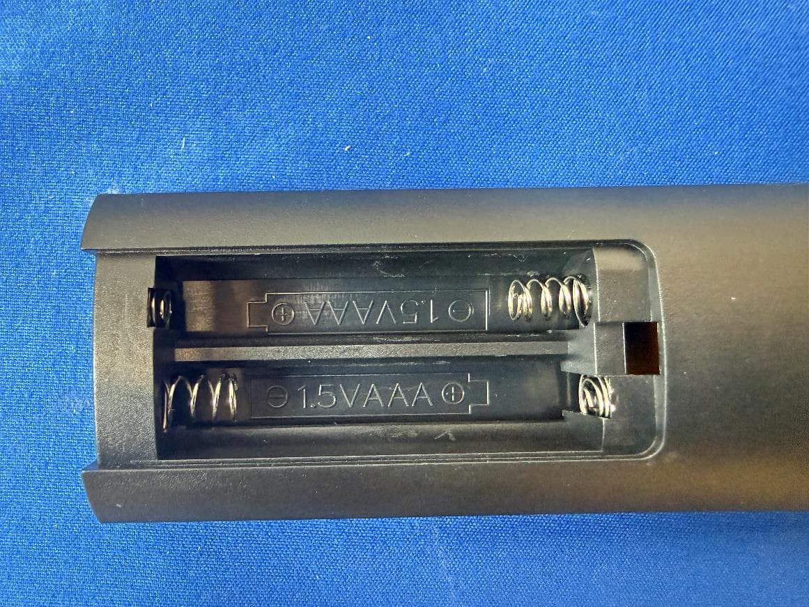
Click to zoom
Application Details
- Equipment Class
- DTS - Digital Transmission System
- Date of Grant
- Aug 26, 2026
- Application Purpose
- Original Equipment
- Equipment Note
- 2.4G Remote control
- Frequency Range
- 2402.00000000 - 2402.00000000
- Country
- China
Documents & Files
Document Text
Text extracted from the exhibit documents filed with the FCC. Open a document above to read the original.
Users Manual
Single remote control technology CCT Product presentation Detailed description of product functions Pairing method Welcome to use this product, we can use remote control wireless control of the light bulb, can adjust the brightness of the LED bulb. CCT, timing, remote control is equipped with a variety of dimming shortcut keys, a variety of dimming modes required for life, so that you experience the fun of smart bulbs and the convenience of life. Switch: Short press to turn the light on or off Within 5 seconds of the LED bulb, long press the "Switch" button and the bulb flashes three times continuously, indicating that the pairing is successful. Timing button: Short press to set time for one hour, long press to cancel timing APP Instructions Increase brightness button: Long press to increase brightness quickly, short press to increase brightness slowly Pair button. In order to ensure that the application can successfully control the device, please click this button within 5 seconds after the device is powered on. If the device flashes or beeps, it means that the phone has been successfully paired with the device, and then the device can be controlled through the application. CCT button: Long press to quickly increase the color temperature, short press to slowly increase the color temperature Lower brightness button: Long press to quickly increase the brightness, short press to slowly reduce the brightness Bulb information Lower CCT button: Long press to quickly lower the color temperature, short press to slowly lower the color temperature Product Name: Remote control LED bulb Natural Light Mode: Press to feel the comfort of natural light Notes: remote control: 2.4G remote control Switch CCT button: Short press to convert three color temperatures 1.Please check that the bulb and remote control are paired before use. Power: 1W/6W/9W Nightlight button: ap to enter nightlight mode 2.The remote control and the LED bulb need to be the same brand. voltage120V Breastfeeding button: Suitable for night feeding 3.If the remote control is not used for a long time, take out the battery. Color temperature: 3000-6500K Working button: suitable for work 4.Without obstacles, the maximum remote control range of the remote control is 35 meters. Lamp holder E26 Reading button: Suitable for reading books 5.Make sure the light bulb is powered up to pair the remote control before use. FCC Statement 1.This device complies with Part 15 of the FCC Rules. Operation is subject to thefollowing two conditions: (1)This device may not cause harmful interference.(2)This device must accept any interference received, including interference that maycause undesired operation. 2.Changes or modifications not expressly approved by the party responsible forcompliance could void the user’s authority to operate the equipment. Note:This equipment has been tested and found to comply with the limits for a class Bdigital device,pursuant to Part 15 of the FCC Rules. These limits are designed to providereasonable protection against harmful interference in a residential installation. This equipment generates uses and can radiate radio frequency energy and,if not installed and used in accordance with the instructions,may cause harmful interference to radio communications.However,there is no guarantee that interference will not occur in a particular installation.if this equipment does cause harmful interference to radio or television reception,which can be determined by turning the equipment off and on,the user is encouraged to try to correct the interference by one or more of the following measures: •Reorient or relocate the receiving antenna. •Increase the separation between the equipment and receiver. •Connect the equipment into an outlet on a circuit different from that to which thereceiver is connected. •Consult the dealer or an experienced radio/TV technician for help. The device has been evaluated to meet general RF exposure requirement. The device can be used in portable exposure condition without restriction FCC Statement 1.This device complies with Part 15 of the FCC Rules. Operation is subject to thefollowing two conditions: (1)This device may not cause harmful interference.(2)This device must accept any interference received, including interference that maycause undesired operation. 2.Changes or modifications not expressly approved by the party responsible forcompliance could void the user’s authority to operate the equipment. Note:This equipment has been tested and found to comply with the limits for a class Bdigital device,pursuant to Part 15 of the FCC Rules. These limits are designed to providereasonable protection against harmful interference in a residential installation. This equipment generates uses and can radiate radio frequency energy and,if not installed and used in accordance with the instructions,may cause harmful interference to radio communications.However,there is no guarantee that interference will not occur in a particular installation.if this equipment does cause harmful interference to radio or television reception,which can be determined by turning the equipment off and on,the user is encouraged to try to correct the interference by one or more of the following measures: •Reorient or relocate the receiving antenna. •Increase the separation between the equipment and receiver. •Connect the equipment into an outlet on a circuit different from that to which thereceiver is connected. •Consult the dealer or an experienced radio/TV technician for help. The device has been evaluated to meet general RF exposure requirement. The device can be used in portable exposure condition without restriction
External Photos
External Serial model No.
ID Label/Location Info
20*56mm
Internal Photos
Internal Antenna
RF Exposure Info
RF EXPOSURE EVALUATION EUT Specification EUT 2.4G Remote control Model Number 12 Key position 2.4GRemote control 1-2 FCC ID 2BLOO-CD12KEY Antenna gain (Max) 0 dBi Operation Frequency 2402MHz, 2426MHz, 2480MHz Rating 3V (2 x 1.5V AA batteries) Classification Per Stipulated Test Standard §15.247(i), §2.1093 Modulation GFSK Max. output power -10.89dBm(0.08mW) Test Requirement: According to ß15.247(i) and ß1.1307(b)(1), systems operating under the provisions of this section shall be operated in a manner that ensures that the public is not exposed to radio frequency energy level in excess of the Commission’s guidelines. Routine SAR evaluation refers to that specifically required by ß2.1093, using measurements or computer simulation. When routine SAR evaluation is not required, portable transmitters with output power greater than the applicable low threshold require SAR evaluation to quality for TCB approval. One antenna is available for the EUT. The minimum separation distance is 5mm. 802.15.4: Transmit Frequency (MHz) Mode Measured Power (dBm) Tune up Power (dBm) Max tune up power(dBm) Calculation Result 1-g SAR 2402 GFSK -10.89 -10±1 -9 0.049127 3 According to KDB 447498, no stand-alone required for BT antenna, and no simultaneous SAR measurement is required. Signature: Alan He Date: 2026-6-23
Test Report
Appendix A Duty Cycle Condition Mode Frequency (MHz) Antenna Duty Cycle (%) Correction Factor (dB) 1/T (kHz) NVNT 2.4G 2402 Ant1 14.11 8.5 2.58 NVNT 2.4G 2426 Ant1 14.11 8.5 2.58 NVNT 2.4G 2480 Ant1 14.07 8.52 2.58 Duty Cycle NVNT 2.4G 2402MHz Ant1 Duty Cycle NVNT 2.4G 2426MHz Ant1 Duty Cycle NVNT 2.4G 2480MHz Ant1 Maximum Peak Conducted Output Power Condition Mode Frequency (MHz) Antenna Conducted Power (dBm) Limit Conducted(dBm) Verdict NVNT 2.4G 2402 Ant1 -10.89 21 Pass NVNT 2.4G 2426 Ant1 -13.38 21 Pass NVNT 2.4G 2480 Ant1 -13.16 21 Pass Peak Power NVNT 2.4G 2402MHz Ant1 Peak Power NVNT 2.4G 2426MHz Ant1 Peak Power NVNT 2.4G 2480MHz Ant1 -6dB Bandwidth Condition Mode Frequency (MHz) Antenna -6 dB Bandwidth (MHz) Limit -6 dB Bandwidth (MHz) Verdict NVNT 2.4G 2402 Ant1 0.6473 0.5 Pass NVNT 2.4G 2426 Ant1 0.6765 0.5 Pass NVNT 2.4G 2480 Ant1 0.7146 0.5 Pass -6dB Bandwidth NVNT 2.4G 2402MHz Ant1 -6dB Bandwidth NVNT 2.4G 2426MHz Ant1 -6dB Bandwidth NVNT 2.4G 2480MHz Ant1 Occupied Channel Bandwidth Condition Mode Frequency (MHz) Antenna 99% OBW (MHz) NVNT 2.4G 2402 Ant1 1.0876 NVNT 2.4G 2426 Ant1 1.112 NVNT 2.4G 2480 Ant1 1.0976 OBW NVNT 2.4G 2402MHz Ant1 OBW NVNT 2.4G 2426MHz Ant1 OBW NVNT 2.4G 2480MHz Ant1 Maximum Power Spectral Density Level Condition Mode Frequency (MHz) Antenna Conducted PSD (dBm/3kHz) Duty Factor (dB) Total PSD (dBm/3kHz) Limit (dBm/3kHz) Verdict NVNT 2.4G 2402 Ant1 -24.96 8.5 -16.46 8 Pass NVNT 2.4G 2426 Ant1 -27 8.5 -18.5 8 Pass NVNT 2.4G 2480 Ant1 -28.63 8.52 -20.11 8 Pass PSD NVNT 2.4G 2402MHz Ant1 PSD NVNT 2.4G 2426MHz Ant1 PSD NVNT 2.4G 2480MHz Ant1 Band Edge Condition Mode Frequency (MHz) Antenna Max Value (dBc) Limit (dBc) Verdict NVNT 2.4G 2402 Ant1 -33.84 -20 Pass NVNT 2.4G 2480 Ant1 -36.04 -20 Pass Band Edge NVNT 2.4G 2402MHz Ant1 Ref Band Edge NVNT 2.4G 2402MHz Ant1 Emission Band Edge NVNT 2.4G 2480MHz Ant1 Ref Band Edge NVNT 2.4G 2480MHz Ant1 Emission Conducted RF Spurious Emission Condition Mode Frequency (MHz) Antenna Max Value (dBc) Limit (dBc) Verdict NVNT 2.4G 2402 Ant1 -31.43 -20 Pass NVNT 2.4G 2426 Ant1 -28.29 -20 Pass NVNT 2.4G 2480 Ant1 -28.7 -20 Pass Tx. Spurious NVNT 2.4G 2402MHz Ant1 Ref Tx. Spurious NVNT 2.4G 2402MHz Ant1 Emission Tx. Spurious NVNT 2.4G 2426MHz Ant1 Ref Tx. Spurious NVNT 2.4G 2426MHz Ant1 Emission Tx. Spurious NVNT 2.4G 2480MHz Ant1 Ref Tx. Spurious NVNT 2.4G 2480MHz Ant1 Emission
Test Report
TRF No.: 04-E001-0B TRF Originator: GTG TRF Date: 2023-12-13 Web: www.gtggroup.com E-mail: [email protected] Tel.: 86-400 755 8988 CFR 47 FCC PART 15 SUBPART C TEST REPORT For 2.4G Remote control MODEL NUMBER: 12 Key position 2.4GRemote control 1-3, 1-3-2, RGB-1, RGB-2,1- 5, 1-2 REPORT NUMBER: E04A26041313F00101 ISSUE DATE: June 23, 2026 FCC ID: 2BLOO-CD12KEY Prepared for Zhaoqing Chendong Optoelectronic Technology Co., Ltd. Building 2, Block 2, Guangdong-Guangxi Cooperation Zone, Pingfeng Town, Fengkai County, Zhaoqing City, Guangdong Province Prepared by Guangdong Global Testing Technology Co., Ltd. Room 101-105, 203-210, Building 1, No.2, Keji 8 Road, Songshan Lake Park, Dongguan city, Guangdong, People’s Republic of China, 523808 This report is based on a single evaluation of the submitted sample(s) of the above mentioned product, it does not imply an assessment of the production of the products. This report shall not be reproduced, except in full, without the written approval of Guangdong Global Testing Technology Co., Ltd. REPORT NO.: E04A26041313F00101 Page 2 of 40 TRF No.: 04-E001-0B Global Testing , Great Quality. Revision History Rev. Issue Date Revisions Revised By V0 June 22, 2026 Initial Issue REPORT NO.: E04A26041313F00101 Page 3 of 40 TRF No.: 04-E001-0B Global Testing , Great Quality. Summary of Test Results Test Item Clause Limit/Requirement Result Antenna Requirement N/A FCC Part 15.203/15.247 (c) Pass AC Power Line Conducted Emission ANSI C63.10-2020, Clause 6.2 FCC Part 15.207 N/A Conducted Output Power ANSI C63.10-2020, Clause 11.9.1.2 FCC Part 15.247 (b)(3) Pass 6dB Bandwidth and 99% Occupied Bandwidth ANSI C63.10-2020, Clause 11.8.2 FCC Part 15.247 (a)(2) Pass Power Spectral Density ANSI C63.10-2020, Clause 11.10.2 FCC Part 15.247 (e) Pass Conducted Band edge and spurious emission ANSI C63.10-2020, Clause 11.11 FCC Part 15.247(d) Pass Radiated Band edge and Spurious Emission ANSI C63.10-2020, Clause 11.12 FCC Part 15.205/15.209 Pass Duty Cycle ANSI C63.10-2020, Clause 11.6 None; for reporting purposes only. Pass *This test report is only published to and used by the applicant, and it is not for evidence purpose in China. *The measurement result for the sample received is <Pass> according to <CFR 47 FCC PART 15 SUBPART C(DTS)> when <Accuracy Method> decision rule is applied. REPORT NO.: E04A26041313F00101 Page 4 of 40 TRF No.: 04-E001-0B Global Testing , Great Quality. CONTENTS 1. ATTESTATION OF TEST RESULTS ..................................................................................... 5 2. TEST METHODOLOGY ......................................................................................................... 6 3. FACILITIES AND ACCREDITATION ..................................................................................... 6 4. CALIBRATION AND UNCERTAINTY ................................................................................... 7 4.1. MEASURING INSTRUMENT CALIBRATION ........................................................... 7 4.2. MEASUREMENT UNCERTAINTY ............................................................................ 7 5. EQUIPMENT UNDER TEST .................................................................................................. 8 5.1. DESCRIPTION OF EUT ........................................................................................... 8 5.1. CHANNEL LIST ........................................................................................................ 8 5.2. MAXIMUM CONDUCTED OUTPUT POWER ........................................................... 8 5.3. TEST CHANNEL CONFIGURATION ........................................................................ 8 5.4. THE WORSE CASE POWER SETTING PARAMETER ............................................ 9 5.5. DESCRIPTION OF AVAILABLE ANTENNAS ........................................................... 9 5.6. SUPPORT UNITS FOR SYSTEM TEST ................................................................. 10 5.7. SETUP DIAGRAM .................................................................................................. 10 6. MEASURING EQUIPMENT AND SOFTWARE USED......................................................... 11 7. ANTENNA PORT TEST RESULTS ..................................................................................... 12 7.1. Conducted Output Power ........................................................................................ 12 7.2. 6dB Bandwidth ........................................................................................................ 14 7.1. Power Spectral Density ........................................................................................... 16 7.2. Conducted Band edge and spurious emission ........................................................ 17 7.3. Duty Cycle .............................................................................................................. 19 8. RADIATED TEST RESULTS ............................................................................................... 20 9. ANTENNA REQUIREMENT ................................................................................................ 37 10. AC POWER LINE CONDUCTED EMISSION ......................................................... 38 REPORT NO.: E04A26041313F00101 Page 5 of 40 TRF No.: 04-E001-0B Global Testing , Great Quality. 1. ATTESTATION OF TEST RESULTS Applicant Information Company Name: Zhaoqing Chendong Optoelectronic Technology Co., Ltd. Address: Building 2, Block 2, Guangdong-Guangxi Cooperation Zone, Pingfeng Town, Fengkai County, Zhaoqing City, Guangdong Province Manufacturer Information Company Name: Zhaoqing Chendong Optoelectronic Technology Co., Ltd. Address: Building 2, Block 2, Guangdong-Guangxi Cooperation Zone, Pingfeng Town, Fengkai County, Zhaoqing City, Guangdong Province EUT Information Product Description: 2.4G Remote control Model: 12 Key position 2.4GRemote control 1-3 Series Model: 1-3-2, RGB-1, R…
Text truncated - open the document above for the full version.
Test Report
FSH2-2G4-TX 2024/10/25 Product specification Quick Reference Data Antenna module on the system board Frequenc Range 2400 ~ 2500GHz Ant. Port Input Pwr. (dBm) 0 (Typ. BT class 2 output power) Tot. Rad. Pwr. (dBm) -1.2 (Input pwr – loss pwr) Peak EIRP(dBm) 0 dBi Directivity (dBi) 1 (all direction antenna) Efficiency (dB) 1.0% Gain (dBi) 0 (Avg Gain XY-plane) Maximum Power (dBm) 0 (XY-plane) Minimum Power (dBm) 0(XY-plane) Avg. Power (dBm) 0(XY-plane) Input Impendence(ohm) 50 Polarization Type Vertical & Horizontal V.S.W.R <6 All the technical data and information contained herein are subject to change without prior notice. FSH2-2G4-TX 2024/10/25 Antenna Layout Unit: mm Antenna Gain Unit in dBi @2.44GHz XY-plane XZ-plane YZ-plane Efficiency Peak Avg. Peak Avg. Peak Avg. Module Board 0 0 0 0 0 0 0 FSH2-2G4-TX 2024/10/25 Return Loss VSWR FSH2-2G4-TX 2024/10/25 3D radiation pattern diagram 2D radiation pattern diagram FSH2-2G4-TX 2024/10/25 Quick Reference Data-TEST 2.4G 2.45G 2.5G Return Loss -TEST -9.1777dB -15.854dB -10.934dB VSWR-TEST 2.0647 1.3791 1.8027 Impendence-TEST 41.834Ω 36.292Ω 50.699Ω All the technical data and information contained herein are subject to change without prior notice. Matching circuit FSH2-2G4-TX 2024/10/25 Return Loss -TEST 2.4G: -9.1777dB; 2.45G:-15.854dB; 2.5G:-10.934dB。 VSWR-TEST 2.4G:2.0647; 2.45G:1.3791; 2.5G:1.8027。 FSH2-2G4-TX 2024/10/25 Impendence 2.4G:41.834Ω,-32.899Ω 2.0162pF; 2.45G:36.292Ω,-1.0842Ω 59.915pF; 2.5G:50.699Ω,30.091Ω 1.9157nH。 FSH2-2G4-TX 2024/10/25
Test Setup Photos
Radiated Band edge and Spurious Emission
Contact Information
Applicant
Wan XiaoLong(Sales Manager)
[email protected]Fax: N/A
Technical Contact
Picus Advisors US LLClvan Wang
5855 SOVEREIGN DRSTE B- 1 · HOUSTON, 77036 · United States
Test Firm
Guangdong Global Testing Technology Co., Ltd.Shawn Wen
Technical Specifications
| # | Rule Parts | Frequency Range | Power Output |
|---|---|---|---|
| 1 | 15C | 2.40 GHz - 2.40 GHz | 100.00 µW |
| 2 | 15C | 2.43 GHz - 2.43 GHz | 100.00 µW |
| 3 | 15C | 2.48 GHz - 2.48 GHz | 100.00 µW |