2BLVKADAPETVPLUSAdapet V Plus
Adapet Medical INC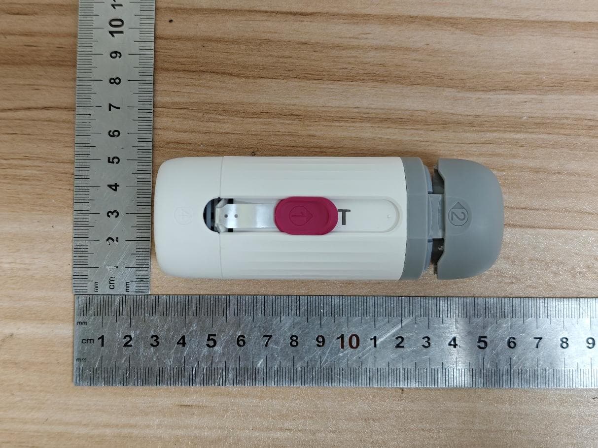
Click to zoom
Application Details
- Equipment Class
- DTS - Digital Transmission System
- Date of Grant
- Feb 04, 2026
- Application Purpose
- Original Equipment
- Equipment Note
- Adapet V Plus
- Frequency Range
- 2402.00000000 - 2480.00000000
- Company
- Adapet Medical INC
- Country
- Canada
Documents & Files
Document Text
Text extracted from the exhibit documents filed with the FCC. Open a document above to read the original.
Attestation Statements
Adapet Medical INC Date: 1/19/2026 Federal Communications Commissions Authorization and Evaluation Division 7435 Oakland Mills Road Columbia, MD 21046 RE: CFR 47 §2.911 (d)(5) Attestation FCC ID: 2BLVKADAPETVPLUS Grantee’s FRN: 0036192979 1. Adapet Medical INC certifies that the equipment for which authorization is sought is not “covered” equipment prohibited from receiving an equipment authorization pursuant to section 2.903 of the FCC rules. 2. Adapet Medical INC certifies that, the device does not have cybersecurity and / or anti- virus software produced or provided by Kaspersky Lab, Inc. or any of its successors and assignees, identified on the Covered List installed on the device, nor will it be installed by the applicant anytime after certification. 3. Adapet Medical INC certifies that, as of the date of the filing of the application, the applicant is not identified on the Covered List as an entity producing “covered” equipment and is not an affiliate or subsidiary of an entity identified on the Covered List. Sincerely yours, Name: Fan Yu Job Title: General Manager Company Name: Adapet Medical INC
Attestation Statements
Adapet Medical INC Date: 1/26/2026 Federal Communications Commissions Authorization and Evaluation Division 7435 Oakland Mills Road Columbia, MD 21046 RE: CFR 47 §2.911 (d)(7) Agent Designation Attestation FCC ID: 2BLVKADAPETVPLUS Grantee FRN: 0036192979 Adapet Medical INC as required by section 2.911(d)(7), designates the following agent, located in the United States, for purposes of acting as the applicant’s agent for service of process. The applicant acknowledges that they will maintain an agent for no less than one year after the grantee has terminated all marketing and importation or the conclusion of any Commission-related proceeding involving the equipment. The applicant further acknowledges their responsibility under CFR 47 §2.929(c) to inform the FCC whenever the agent information changes. U.S. Agent Information: Contact Person: Fan Yu Company Name: Adapet Medical, LLC Company Address: 9407 NE Vancouver Mall Dr., Suite 104 # 2333 WA Email: [email protected] Note: Adapet Medical, LLC does not do any other business with the FCC. Sincerely yours, Name: Fan Yu Job Title: General Manager Company Name: Adapet Medical INC
Attestation Statements
Date: 1/26/2026 Federal Communications Commissions Authorization and Evaluation Division 7435 Oakland Mills Road Columbia, MD 21046 RE: CFR 47 §2.911 (d)(7) FCC US Agent Letter of Attestation Grantee Code: 2BLVK Grantee's FRN: 0036192979 To whom it may concern: FCC US Agent Agent Company Name:Adapet Medical, LLC Agent Contact Name: Fan Yu Agent US Address: 9407 NE Vancouver Mall Dr., Suite 104 # 2333 WA Agent Email Address: [email protected] Note: Adapet Medical, LLC does not do any other business with the FCC. This letter is to confirm that we have accepted the responsibility to act as US Agent on behalf of Adapet Medical INC (“the applicant”). We are aware of the requirements and responsibilities of the applicant’s agent for service of process as outlined in the FCC section 2.911(d)(7) and Report and Order FCC 22-84 paragraph 63. Sincerely, Signature Authorized Agent Contact Person Name: Fan Yu Agent contact Job Title: General Manager Agent Company name: Adapet Medical, LLC
Cover Letter(s)
Adapet Medical INC Date: 1/19/2026 UL Verification Services Inc. 47173 Benicia Street Fremont, CA 94538, USA To whom it may concern: I, the undersigned, hereby authorize UL Verification Services Inc. to act on our behalf in all manners relating to application for equipment authorization, including signing of all documents relating to these matters. Any and all acts carried out by UL Verification Services Inc. on our behalf shall have the same effect as acts of our own. I, the undersigned, hereby certify that we are not subject to a denial of federal benefits, that includes FCC benefits, pursuant to Section 5301 of the Anti-Drug Abuse Act of 1988, 21 U.S.C. § 862 because of a conviction for possession or distribution of a controlled substance. In authorizing UL Verification Services Inc. as our representative, we still recognize that we are responsible to: a) fulfill the requirements for the scope of certification requested, including implementing any appropriate changes requested by UL Verification Services Telecommunications Certification Body (TCB) and / or the FCC; b) supply any and all information needed for the evaluation of the products for which certification is sought; c) make claims regarding certification only in respect of the scope for which certification has been granted; d) not use our product certification in such a manner as to bring the TCB or FCC into disrepute and to not make any statement regarding product certification which the TCB or FCC may consider misleading or unauthorized; e) discontinue use of all advertising matter that contains any reference thereto and complies with any and all actions required by the FCC upon suspension or cancellation of certification; f) use certification only to indicate that products are certified in conformity with specified standards; g) endeavor to ensure that no certificate or report or any part thereof is used in a misleading manner, and any copies of the grants/certificates shall be reproduced in their entirety; h) comply with the requirements of the TCB and FCC, including the use of marks and label information prescribed for the scope of certification, when making reference to product certification in communication media such as documents, brochure or advertisements; i) comply with the requirements for certification, supply any information needed for evaluation of products to be certified and, where applicable, make provision for the participation of observers; j) ensure that products marketed under the scope of the requested certification continue to comply with the certification requirements; k) provide a sample of a production unit for testing within 30 days of the request should this product be selected as part of either the TCB’s or the FCC’s market surveillance requirements; l) keep a record of all complaints relating to product’s compliance with requirements of relevant standard; make records available to UL or FCC when requested; take appropriate action with respect to such complaints and any deficiencies found in the product that affect compliance with requirements for certification; document the actions taken with respect to complaints and/or deficiencies; m) inform the TCB immediately of any changes that may affect its ability to comply with the certification requirements. This authorization is valid until further written notice from the applicant. Sincerely Yours, Company Name: Adapet Medical INC Contact Name: Fan Yu Title of Person: General Manager Address: 1550 W 36th ave, Vancouver, V6M1J8 Canada
Cover Letter(s)
Adapet Medical INC Federal Communications Commission 7435 Oakland Mills Road Columbia MD 21046 Subject: Request for Confidentiality FCC ID: 2BLVKADAPETVPLUS To Whom It May Concern: Pursuant to the provisions of Sections 0.457 and 0.459 of the Commission’s rules (47 CFR §§ 0.457, 0.459), we are requesting the Commission to withhold the following attachments as confidential document from public disclosure indefinitely. Schematic Diagram Block Diagram Theory of Operation Above mentioned document contains detailed system and equipment description are considered as proprietary information in operation of the equipment. The public disclosure of above documents might be harmful to our company and would give competitor an unfair advantage in the market. It is our understanding that all measurement test reports, FCC ID label format and correspondent during certification review process cannot be granted as confidential documents and those information will be available for public review once the grant of equipment authorization is issued. Best Regards Company Name: Adapet Medical INC Contact Name: Fan Yu Title of Person: General Manager Address: 1550 W 36th ave, Vancouver, V6M1J8 Canada Date: 01/19/2026
External Photos
External Photographs Page 2 of 3 This report shall not be reproduced except in full, without the written approval of UL Verification Services (Guangzhou) Co., Ltd, Song Shan Lake Branch. Page 3 of 3 This report shall not be reproduced except in full, without the written approval of UL Verification Services (Guangzhou) Co., Ltd, Song Shan Lake Branch.
ID Label/Location Info
Note: 1.Product Label applied using permanent adhesive. It is user-accessible and non- detachable. Label location
Internal Photos
Internal Photographs Page 2 of 7 This report shall not be reproduced except in full, without the written approval of UL Verification Services (Guangzhou) Co., Ltd, Song Shan Lake Branch. Page 3 of 7 This report shall not be reproduced except in full, without the written approval of UL Verification Services (Guangzhou) Co., Ltd, Song Shan Lake Branch. Page 4 of 7 This report shall not be reproduced except in full, without the written approval of UL Verification Services (Guangzhou) Co., Ltd, Song Shan Lake Branch. Page 5 of 7 This report shall not be reproduced except in full, without the written approval of UL Verification Services (Guangzhou) Co., Ltd, Song Shan Lake Branch. Page 6 of 7 This report shall not be reproduced except in full, without the written approval of UL Verification Services (Guangzhou) Co., Ltd, Song Shan Lake Branch. Page 7 of 7 This report shall not be reproduced except in full, without the written approval of UL Verification Services (Guangzhou) Co., Ltd, Song Shan Lake Branch. Chip Antenna
RF Exposure Info
FCC ID: 2BLVKADAPETVPLUS According to 447498 D04 Interim General RF Exposure Guidance v01, 2.1.4 MPE-Based Exemption An alternative to the SAR-based exemption is provided in § 1.1307(b)(3)(i)(C), for a much wider frequency range, from 300 kHz to 100 GHz, applicable for separation distances greater or equal to λ/2π, where λ is the free-space operating wavelength in meters. The MPE-based test exemption condition is in terms of ERP, defined as the product of the maximum antenna gain and the delivered maximum time-averaged power.10 For this case, a RF source is an RF exempt device if its ERP (watts) is no more than a frequency-dependent value, as detailed tabular form in Appendix B. These limits have been derived based on the basic specifications on Maximum Permissible Exposure (MPE) considered for the FCC rules in § 1.1310(e)(1). B.4 SAR-based Exemption SAR-based thresholds are derived based on frequency, power, and separation distance of the RF source. The formula defines the thresholds in general for either available maximum time- averaged power or maximum time-averaged ERP, whichever is greater. If the ERP of a device is not easily determined, such as for a portable device with a small form factor, the applicant may use the available maximum time-averaged power exclusively if the device antenna or radiating structure does not exceed an electrical length of λ/4. As for devices with antennas of length greater than λ/4 where the gain is not well defined, but always less than that of a half-wave dipole (length λ/2), the available maximum time-averaged power generated by the device may be used in place of the maximum time-averaged ERP, where that value is not known. The separation distance is the smallest distance from any part of the antenna or radiating structure for all persons, during operation at the applicable ERP. In the case of mobile or portable devices, the separation distance is from the outer housing of the device where it is closest to the antenna. The SAR-based exemption formula of § 1.1307(b)(3)(i)(B), repeated here as Formula (B.2), applies for single fixed, mobile, and portable RF sources with available maximum time-averaged power or effective radiated power (ERP), whichever is greater, of less than or equal to the threshold Pth (mW). This method shall only be used at separation distances from 0.5 cm to 40 cm and at frequencies from 0.3 GHz to 6 GHz (inclusive). Pth is given by Formula (B.2). and f is in GHz, d is the separation distance (cm), and ERP 20cm is per Formula (B.1). The example values shown in Table B.2 are for illustration only. 1. SAR test exclusion threshold for 2.402GHz~2.480GHz is 3 mW. -The maximum tune-up power with tolerance is -1.5 dBm=0.708 mW, the antenna is 5.05 dBi, so the ERP = EIRP – 2.15 = 1.4 dBm=1.380 mW. - When the minimum test separation distance is < 5 mm, a distance of 5 mm is applied to determine SAR test exclusion. 2. Conclusion: No SAR is required.
Test Report
The results reported herein have been performed in accordance with the laboratory’s terms of accreditation. This report shall not be reproduced except in full without the written approval of the Laboratory. The results in this report apply to the test sample(s) mentioned above at the time of the testing period only and are not to be used to indicate applicability to other similar products. CFR 47 FCC PART 15 SUBPART C ISED RSS-247 Issue 4 TEST REPORT For Adapet V Plus MODEL NUMBER: V Plus REPORT NUMBER: 4792034741-1-RF-1 ISSUE DATE: January 9, 2026 FCC ID: 2BLVKADAPETVPLUS IC: 33656-ADAPETVPLUS Prepared for Adapet Medical INC. 1550 W 36th Ave, Vancouver, BC, Canada Prepared by UL Verification Services (Guangzhou) Co., Ltd, Song Shan Lake Branch Room 101, Building 2, No.4, Information Road, Songshan Lake, Dongguan, Guangdong, China Tel: +86 769 22038881 Fax: +86 769 33244054 Website: www.ul.com REPORT NO.: 4792034741-1-RF-1 Page 2 of 60 UL Verification Services (Guangzhou) Co., Ltd, Song Shan Lake Branch FORM NO: 10-SL-F0035 This report shall not be reproduced except in full, without the written approval of UL Verification Services (Guangzhou) Co., Ltd, Song Shan Lake Branch. Revision History Rev. Issue Date Revisions Revised By V0 January 9, 2026 Initial Issue REPORT NO.: 4792034741-1-RF-1 Page 3 of 60 UL Verification Services (Guangzhou) Co., Ltd, Song Shan Lake Branch FORM NO: 10-SL-F0035 This report shall not be reproduced except in full, without the written approval of UL Verification Services (Guangzhou) Co., Ltd, Song Shan Lake Branch. Summary of Test Results Test Item Clause Limit/Requirement Result Antenna Requirement N/A FCC Part 15.203/15.247 (c) RSS-GEN Clause 6.8 Pass AC Power Line Conducted Emission ANSI C63.10-2020, Clause 6.2 FCC Part 15.207 RSS-GEN Clause 8.8 N/A Conducted Output Power ANSI C63.10-2020, Clause 11.9.1.2 FCC Part 15.247 (b)(3) RSS-247 Clause 6.3.2 Pass 6dB Bandwidth and 99% Occupied Bandwidth ANSI C63.10-2020, Clause 11.8.1 FCC Part 15.247 (a)(2) RSS-247 Clause 6.3.1 (a) RSS-Gen Clause 6.7 Pass Power Spectral Density ANSI C63.10-2020, Clause 11.10.2 FCC Part 15.247 (e) RSS-247 Clause 6.3.1 (b) Pass Conducted Band edge and spurious emission ANSI C63.10-2020, Clause 11.11 FCC Part 15.247(d) RSS-247 Clause 6.6 Pass Radiated Band edge and Spurious Emission ANSI C63.10-2020, Clause 11.12 FCC Part 15.247 (d) FCC Part 15.205/15.209 RSS-247 Clause 6.6 RSS-GEN Clause 8.9 Pass Duty Cycle ANSI C63.10-2020, Clause 11.6 None; for reporting purposes only. Pass Note: 1. N/A: In this whole report not applicable. 2. For ISED, this report is also performed according to ANSI C63.10-2020 + Cor.1-2023 + C63.10a-2024 + Errata to C63.10a-2024 standards. *This test report is only published to and used by the applicant, and it is not for evidence purpose in China. *The measurement result for the sample received is <Pass> according to <CFR 47 FCC PART 15 SUBPART C ISED RSS-247 Issue 4> when <Simple Acceptance> decision rule is applied. REPORT NO.: 4792034741-1-RF-1 Page 4 of 60 UL Verification Services (Guangzhou) Co., Ltd, Song Shan Lake Branch FORM NO: 10-SL-F0035 This report shall not be reproduced except in full, without the written approval of UL Verification Services (Guangzhou) Co., Ltd, Song Shan Lake Branch. CONTENTS 1. ATTESTATION OF TEST RESULTS ..................................................................................... 6 2. TEST METHODOLOGY ......................................................................................................... 7 3. FACILITIES AND ACCREDITATION ..................................................................................... 7 4. CALIBRATION AND UNCERTAINTY ................................................................................... 8 4.1. MEASURING INSTRUMENT CALIBRATION ........................................................... 8 4.2. MEASUREMENT UNCERTAINTY ............................................................................ 8 5. EQUIPMENT UNDER TEST .................................................................................................. 9 5.1. DESCRIPTION OF EUT ........................................................................................... 9 5.2. CHANNEL LIST ........................................................................................................ 9 5.3. MAXIMUM POWER .................................................................................................. 9 5.4. TEST CHANNEL CONFIGURATION ........................................................................ 9 5.5. THE WORSE CASE POWER SETTING PARAMETER .......................................... 10 5.6. DESCRIPTION OF AVAILABLE ANTENNAS ......................................................... 10 5.7. SUPPORT UNITS FOR SYSTEM TEST ................................................................. 10 6. MEASURING EQUIPMENT AND SOFTWARE USED......................................................... 11 7. ANTENNA PORT TEST RESULTS ..................................................................................... 14 7.1. CONDUCTED OUTPUT POWER ........................................................................... 14 7.2. 6DB BANDWIDTH AND 99% OCCUPIED BANDWIDTH ........................................ 15 7.3. POWER SPECTRAL DENSITY .............................................................................. 17 7.4. CONDUCTED BAND EDGE AND SPURIOUS EMISSION ..................................... 18 7.5. DUTY CYCLE ......................................................................................................... 20 8. RADIATED TEST RESULTS ............................................................................................... 21 8.1. RESTRICTED BANDEDGE .................................................................................... 29 8.2. SPURIOUS EMISSIONS(1 GHZ~3 GHZ) ............................................................... 32 8.3. SPURIOUS EMISSIONS(3 GHZ~18 GHZ) ..........…
Text truncated - open the document above for the full version.
Test Report
DATA SHEET WIRELESS COMPONENTS Ceramic Chip Antenna ANT3216LL00R2400A 2.4 - 2.5 GHZ 3216 Serie s Product Specification – March 27, 2013 V.0 www.yageo.com Mar. 27, 2013 V0 WIRELESS COMPONENTS 2 6 Product specification Ceramic Chip Antenna FEATURES z Compact size z Omni-directional radiation z Tape & reel automatic mounting z Reflow process compatible z RoHS compliant APPLICATIONS z 2.4 GHz WiFi device z Bluetooth gadget z Zigbee device z ISM band equipment ORDERING INFORMATION All part numbers are identified by the series, packing type, material, size, antenna type, working frequency and packing quantity. PART NUMBER ANT 3216 L L00 R 2400A (1) (2) (3) (4) (5) (6) ( 1 ) PRODUCT ANT = Antenna ( 2 ) SIZE 3216 = 3.2 × 1.6 mm ( 3 ) ANTENNA TYPE L,F,A = Chip Antenna ( 4 ) SERIAL NO. L00 ( 5 ) PACKING TYPE R = Tape and Reel ( 6 ) WORKING FREQUENCY 2400 = 2.4GHz PHYCOMP CTC CAN4311712002453K 12NC 431171200245 www.yageo.com Mar. 27, 2013 V0 WIRELESS COMPONENTS 3 6 Product specification Ceramic Chip Antenna SPECIFICATION DESCRIPTION VALUE Working Frequency 2.4 - 2.5 GHz Bandwidth 160 MHz Polarization Linear Azimuth Beamwidth Omni-directional Peak Gain 5.05 dBi (Typ.) Impedance 50Ω Operating Temperature -40 ~105°C Maximum Power 1W Termination Ni / Sn (Environmentally-Friendly Leadless) Resistance to Soldering Heats 260°C , 10sec. NOTE 1. The specification is defined on Yageo evaluation board Ta b l e 1 O O U U T T L L I I N N E E S S YNH0010 Side ViewTop View Bot t om View T W L C S1S2 Fig. 1 Antenna outlines DIMENSIONS DIMENSION L (mm) 3.20 ±0.15 W (mm) 1.60 ±0.15 T (mm) 1.20 ±0.15 C (mm) 0.40 ±0.20 Table 2 Machinical Dimension TERMINAL NAME FUNCTION S1 Feeding Point S2 Soldering Point Table 3 Termination configuration www.yageo.com Mar. 27, 2013 V0 WIRELESS COMPONENTS 4 6 Product specification Ceramic Chip Antenna YNH0011 Bottom Layer Top Layer 2.5 2.0 3.5 0.4 Matching Circuit 1.8 Unit : mm Unit : mm 1030 18 Fig. 2 Outlook and dimension of evaluation board REFERENCE DESIGN OF EVALUATION BOARD Fig. 3 Details of soldering Pad www.yageo.com Mar. 27, 2013 V0 WIRELESS COMPONENTS 5 6 Product specification Ceramic Chip Antenna 2.0 2.13.0 f (GHz) Return loss (dB) −50 −30 −10 10 30 50 2.2 2.3 2.4 2.5 2.6 2.7 2.8 2.9 YNH0012 1 2 3 Fig. 4 Return loss ELECTRICAL PERFORMANCES YNH0013 Y X Z Z axle X axleY axle Gain (dBi) 5.00 − 0.00 − − 5.00 − − 10.00 − − 15.00 − − 20.00 − − 25.00 − − 30.00 − − 35.00 − Fig. 5 Radiation pattern Max gain = 5.05 dBi, at (180, 60) MEG (mean effective gain)= 0.45dBi Directivity (dB) = 7.15 Efficiency = -1.50dB, 70.74% Evaluation board and XYZ direction Marker data 1. 2.37GHz, -10dB 2. 2.45GHz, -27.3dB 3. 2.53GHz, -10dB www.yageo.com Mar. 27, 2013 V0 WIRELESS COMPONENTS 6 6 Product specification Ceramic Chip Antenna REVISION HISTORY REVISION DATE CHANGE NOTIFICATION DESCRIPTION Version 0 Mar. 27, 2013 - - New datasheet for Ceramic Chip Antenna, 2.4-2.5 GHz application, size 3216 series
Test Setup Photos
Appendix II Setup Photographs RADIATED RF MEASUREMENT SETUP (ABOVE 1 GHz) MEASUREMENT POSITION MEASUREMENT POSITION (X axis) MEASUREMENT POSITION (Y axis) MEASUREMENT POSITION (Z axis) RADIATED RF MEASUREMENT SETUP (30MHz~1GHz) RADIATED RF MEASUREMENT SETUP (Below 30MHz)
Contact Information
Applicant
Fan Yu
[email protected]Fax: 604.235.4105
Technical Contact
Adapet Medical, LLCFan / Yu
9407 NE Vancouver Mall Dr., Suite 104 # 2333 WA · Vancouver, 9407 · United States
Test Firm
UL Verification Services (Guangzhou) Co., Ltd.Stephen Guo
Technical Specifications
| # | Rule Parts | Frequency Range | Power Output |
|---|---|---|---|
| 1 | 15C | 2.40 GHz - 2.48 GHz | 693.00 µW |