2BMDC-LUMOS-24Lumos Smart Sleep Mask
LumosTech, Inc.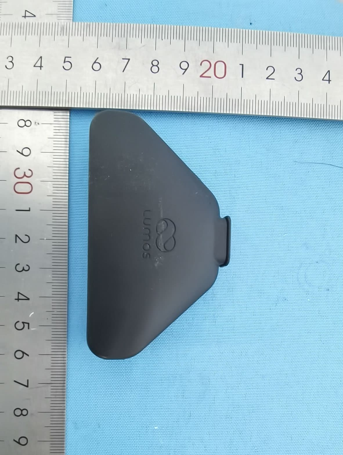
Click to zoom
Application Details
- Equipment Class
- DTS - Digital Transmission System
- Date of Grant
- Dec 23, 2025
- Application Purpose
- Original Equipment
- Equipment Note
- Lumos Smart Sleep Mask
- Frequency Range
- 2402.00000000 - 2480.00000000
- Company
- LumosTech, Inc.
- Country
- United States
Documents & Files
Document Text
Text extracted from the exhibit documents filed with the FCC. Open a document above to read the original.
Users Manual
LumosTech, Inc. Version Date: November 6, 2024 Confidential Page 1 of 12 Lumos Smart Sleep Mask Product Manual LTMKWDGR24 LumosTech, Inc. Version Date: November 6, 2024 Confidential Page 2 of 12 LumosTech, Inc. November 6, 2024 Table of Contents T ABLE OF C ONTENTS 2 1. GENERAL INFORMATION 3 1.1 I NTENDED PURPOSES 3 1.2 C OMPONENTS 3 1.2.1 Fabric sleep mask 3 1.2.2 Electronic components 4 1.2.3. Companion mobile application 4 1.3 V ERSIONS 4 2. USING THE DEVICE 5 2.1 S ETTING UP THE DEVICE 5 2.2 C HARGING 5 2.3 S CHEDULING A PROGRAM 5 2.3 R UNNING A PROGRAM 6 2.4 W EARING THE MASK 8 2.5 P AUSING A PROGRAM 8 2.5 M AINTENANCE 8 3. SAFETY 9 3.1. G ENERAL SAFETY INFORMATION 9 3.1.1 Limitation of liability 9 3.1.2 Visual inspection 9 3.3 U NINTENDED USE 10 4. CONTACT INFORMATION 12 LumosTech, Inc. Version Date: November 6, 2024 Confidential Page 3 of 12 1. General information 1.1 Intended purposes The Lumos Smart Sleep Mask (Lumos Mask) is a device that integrates advanced light technology into a comfortable, regular sleep mask, designed specifically to support individuals facing challenges due to rapidly changing sleep schedules. It is ideal for those experiencing jet lag, adjusting to night shifts, or managing other irregular sleep patterns. By delivering timed light exposure, the Lumos mask helps users adjust to new sleep-wake schedules, making transitions smoother. Additionally, the mask offers a gentle, natural light wake-up feature, allowing users to start their day with morning light exposure without the abruptness of traditional alarms. It is important to note that the Lumos Mask is not intended as a treatment for insomnia, sleep apnea, restless leg syndrome, sleep walking, or any other clinical sleep disorders. It is also not meant for anything other than the usage described on the Lumos website (https://lumos.tech/). 1.2 Components The Lumos Mask has three components: ● A fabric sleep mask cover ● Electronic components ● A mobile application 1.2.1 Fabric sleep mask The sleep mask cover is made of breathable fabric and soft foams compressed together into a pre-designed shape. The 3D-contoured eye regions are designed to prevent the mask from pressing against the eyes. The sleep mask cover has two straps attached by a hook-and- loop mechanism, with an adjustable range that fits most adult head sizes. LumosTech, Inc. Version Date: November 6, 2024 Confidential Page 4 of 12 Figure 1 The fabric mask cover 1.2.2 Electronic components The electronic components emit light flashes according to the programs designed by the companion iOS mobile application. The electronic components include: ● A custom-designed printed circuit board (PCB) ● A lithium-ion battery connected with a micro-USB charging port ● A Bluetooth communication chip ● 6 light-emitting diodes (LED). All the electronic components are enclosed in a V-0 grade fireproof plastic case. Figure 2 The electronic components enclosed in the plastic case 1.2.3. Companion mobile application The Lumos Mask is controlled by its companion iOS mobile application. For study Lumos- 21-01-SCMS0, a testing app specifically designed for this study will be used. 1.3 Versions All versions of Lumos Mask collectively are referred to as Lumos Mask. The current version of Lumos Mask has the following model number, hardware, and software versions: • Model number: LTMKWDGR24 • Operating temperature: -20 ~ 45°C • Hardware: V03-R05.X • Firmware: 5.0.0.10 • Software: Lumos Sleep (iOS, currently 2.3.12.5) LumosTech, Inc. Version Date: November 6, 2024 Confidential Page 5 of 12 2. Using the device 2.1 Setting up the device Upon receiving the device, first insert the electronic part into the fabric mask cover through the Velcro opening on the right side of the mask. Figure 3 Insert the electronic part into the mask 2.2 Charging The Mask can be charged via a USB-C charging cable. Each full charge lasts for 3-4 nights of use. The Mask displays cycles of high and low intensity of amber light while charging, which shuts off after charging completes. Users may check the battery level in the app. Light programs may be prevented from starting when the battery level is too low. No light programs can be run while the Mask is charging. 2.3 Scheduling a program Choose a program from the list of programs available. A program guide is available if not sure about which programs to choose. Once choose a program, follow the instructions to input information such as sleep schedules and travel or night shift schedules. LumosTech, Inc. Version Date: November 6, 2024 Confidential Page 6 of 12 Follow the instructions on when to use the mask. There may be instructions of when to get bright light exposure and when to avoid light exposure. Please note that all user interfaces may subject to change as the app updates. Figure 4 User interface for scheduling a light program and example with a light program 2.3 Running a program Right before going to bed, start the light program from the app by tapping on the “TAP TO START” button to start the program. Confirm that the program is running by the message of “running”. LumosTech, Inc. Version Date: November 6, 2024 Confidential Page 7 of 12 Figure 5 User interface for starting the light program The amber light from the mask indicates program start and stop. Flashing once indicates a program has started, and flashing three times indicates a program has stopped. Figure 6 Program start and stop indicators LumosTech, Inc. Version Date: November 6, 2024 Confidential Page 8 of 12 2.4 Wearing the mask Right after starting the program, put on the mask and go to bed, wearing the mask throughout the night. When putting on the mask, make two straps spread comfortably on the head. Then adjust the hook-and-loop mechanism on the back to the desired level of tightness. 2.5 Pausing a program If the user wakes up in the middle of the night and the light flashes are preventing the user from falling asleep, a pause button on the electronic insert can be pushed…
Text truncated - open the document above for the full version.
Attestation Statements
LumosTech, Inc. Covered Equipment Certification Attestation Letter 2/12/2025 Nemko North America, Inc. 303 River Road Ottawa K1V 1H2 Canada ATTN.: Reviewing Engineer FCC ID: 2BMDC-LUMOS-24 LumosTech, Inc. (“the applicant”) certifies that the equipment for which authorization is sought is not “covered” equipment prohibited from receiving an equipment authorization pursuant to section 2.903 of the FCC rules. Note: If the equipment for which the applicant seeks authorization is produced by any of the entities identified on the current Covered List , the applicant should include an explanation on why the equipment is not “covered” equipment. LumosTech, Inc. (“the applicant”) certifies that, as of the date of the filing of the application, the applicant is not identified on the Covered List as an entity producing “covered” equipment. LumosTech, Inc. (“the applicant”) certifies that the equipment for which authorization is sought does not include cybersecurity or anti-virus software produced or provided by Kaspersky Lab, Inc. or any of its successors and assignees, including equipment with integrated Kaspersky Lab, Inc. (or any of its successors and assignees) cybersecurity or anti-virus software pursuant to DA-24-886 and KDB 986446 D01 Covered Equipment Guidance section B(2a). Printed name: Biquan Luo Title: Founder and CEO Company Name: LumosTech, Inc. Date: 12/2/2024
Attestation Statements
LumosTech, Inc. * the applicant must designate a contact located in the United States for purposes of acting as the applicant’s agent for service of process, regardless of whether the applicant is a domestic or foreign entity. An applicant located in the United States may designate itself as the agent for service of process. U.S. Agent Designation for Service of Process - Certification Attestation Letter February 10, 2025 Nemko North America, Inc. 303 River Road Ottawa K1V 1H2 Canada ATTN.: Reviewing Engineer FCC ID: 2BMDC-LUMOS-24 Per section 2.911(d)(7) of the FCC rules, LumosTech, Inc. (“the applicant”) certifies that the equipment for which authorization is sought is designated to the following U.S. Designated agent* for service of process: Company Name: LumosTech, Inc. Physical U.S. Company Address: 600 W Santa Ana Blvd, Suite 214F Santa Ana, CA, 92701 Agent name: Biquan Luo Agent Email Address: [email protected] FRN: 0036313377 The above contact person accepts the obligation for service of process. The applicant accepts to maintain an agent for no less than one year after the grantee has terminated all marketing and importation or the conclusion of any Commission-related proceeding involving the equipment. Applicant Signed: Designated Agent Signed: (Required, if different to Applicant): Signed: Signed: Printed name: Biquan Luo Printed name: Biquan Luo Title: Founder and CEO Title: Founder and CEO Company Name: LumosTech, Inc. Company Name: LumosTech, Inc. Date: December 2, 2024 Date: December 2, 2024
Cover Letter(s)
LumosTech, Inc. 12/2/2024 Nemko North America, Inc. 303 River Road Ottawa, Ontario, Canada K1V 1H2 AUTHORITY TO ACT AS AGENT - FCC On our behalf, I appoint Dongguan NTC CO., Ltd. Building D, Gaosheng Science and Technology Park, Hongtu Road, Nancheng District, Dongguan City, Guangdong China, to act as our agent in the preparation of this application for equipment certification. I certify that submitted documents properly describe the device or system for which equipment certification is sought. I also certify that each unit manufactured, imported or marketed, as defined in FCC regulations will have affixed to it a label identical to that submitted for approval with this application. In signing this letter, Applicant certifies that neither the applicant nor any party to the application is not subject to a denial of Federal benefits, that include FCC benefits, pursuant to Section 5301 of the Anti-Drug Abuse Act of 1988, 21 U.S.C. § 862 because of a conviction for possession or distribution of a controlled substance. See 47 CFR 1.2002(b) for the definition of a "party" for these purposes. For instances where our authorized agent signs the application for certification on our behalf, I acknowledge that all responsibility for complying with the terms and conditions for certification, as specified by Nemko North America Inc., still resides with us. Sincerely, Printed name: Biquan Luo
Cover Letter(s)
LumosTech, Inc. 12/2/2024 Nemko North America, Inc. 303 River Road Ottawa, Ontario, Canada K1V 1H2 REQUEST FOR CONFIDENTIALITY - FCC FCC ID: 2BMDC-LUMOS-24 Pursuant to Sections 0.457(d)(1)(ii) and 0.459 of the Commission’s Rules and FCC Guidance document 726920, we hereby request confidential treatment of information accompanying this application as outlined below: PERMANENT LONG-TERM CONFIDENTIALITY: Schematics Block Diagrams Theory of Operation The above information contains trade secrets and proprietary information not customarily released to the public. The public disclosure of this information might be harmful to the applicant and provide unjustified benefits to its competitors. The Applicant understands that pursuant to Rule 0.457(d)(1)(ii), disclosure of this Application and all accompanying materials will not be made before the date of the Grant for this Application. Sincerely, Printed name: Biquan Luo Title: Founder and CEO
External Photos
FCC ID: 2BMDC-LUMOS-24 External photos FCC ID: 2BMDC-LUMOS-24 FCC ID: 2BMDC-LUMOS-24 FCC ID: 2BMDC-LUMOS-24 FCC ID: 2BMDC-LUMOS-24 FCC ID: 2BMDC-LUMOS-24 FCC ID: 2BMDC-LUMOS-24 FCC ID: 2BMDC-LUMOS-24
ID Label/Location Info
Label & Location Lumos Smart Sleep Mask LTMKWDGR24 Rating input: 5V 1.0A Internal battery: 3.7V 200mAh, 0.74Wh FCC ID: 2BMDC-LUMOS-24 The product nameplate will be written into the following Bluetooth app as an E-Label. 1. Open the app (Lumos sleep) and connect the Bluetooth function of the product; 2. Click on the "setting" option, then you can access the “Legal and Regulatory” option. Click on it and you will be able to view the FCC ID and the rated information. Details see below:
Internal Photos
FCC ID: 2BMDC-LUMOS-24 Internal photos FCC ID: 2BMDC-LUMOS-24 RF Chip RF Antenna FCC ID: 2BMDC-LUMOS-24
RF Exposure Info
Report No.: NTC2410254F01 Dongguan Nore Testing Center Co., Ltd. Address: Building D, Gaosheng Science and Technology park, Hongtu road, Nancheng district, Dongguan city, Guangdong province, China Web: www.ntc-c.com Tel:+86-769-2202 2444 Fax:+86-769-2202 2799 Page 1 of 11 RF EVALUATION TEST REPORT Applicant......................... : LumosTech, Inc. Address........................... : 600 W Santa Ana Blvd, Suite 214F Santa Ana, CA, 92701 Manufacturer.................... : LumosTech, Inc. Address.......................... : 600 W Santa Ana Blvd, Suite 214F Santa Ana, CA, 92701 Factory ......................... : LumosTech, Inc. Address ......................... : 600 W Santa Ana Blvd, Suite 214F Santa Ana, CA, 92701 Product Name.................. : Lumos Smart Sleep Mask Brand Name..................... : Lumos Model No. ........................ : LTMKWDGR24 FCC ID............................ : 2BMDC-LUMOS-24 Measurement Standard...... : 47 CFR PART 2, Section 2.1093 Receipt Date of Samples.... : October 28, 2024 Date of Tested.................. : October 28, 2024 to November 30, 2024 Date of Report.................. : January 08, 2025 This report shows that above equipment is technically compliant with the requirements of the standards above. All test results in this report apply only to the tested sample(s). Without prior written approval of Dongguan Nore Testing Center Co., Ltd, this report shall not be reproduced except in full. Prepared by Alina Guo / Project Engineer Approved by Iori Fan / Authorized Signatory Report No.: NTC2410254F01 Page 2 of 11 Table of Contents 1. General Description of EUT ................................................................................................................................ 4 2. Test Facility and Location ................................................................................................................................... 6 3. Applicable Standards and References ................................................................................................................ 7 4. Maximum Permissible Exposure Limit ................................................................................................................ 8 5. RF Exposure Evaluation Results ...................................................................................................................... 11 Report No.: NTC2410254F01 Page 3 of 11 Revision History Report Number Description Issued Date NTC2410254F01 Initial Issue 2025-01-08 Report No.: NTC2410254F01 Page 4 of 11 1. General Description of EUT Product Information Product Name: Lumos Smart Sleep Mask Main Model Name: LTMKWDGR24 Additional Model Name: N/A Model difference: N/A S/N: 2410-5725 Brand Name: Lumos Hardware Version: V03-R05.X Software Version: Lumos Sleep (iOS, currently 2.3.12.5) Rating: DC 5V come from adapter DC 3.7V come from internal battery Typical Arrangement: Table-top I/O Port: Refer to the user manual Accessories Information Adapter: N/A Cable: USB cable: 1.0m unshielded, detachable. Other: N/A Additional Information Note: N/A Remark: All the information above are provided by the manufacturer. More detailed feature of the EUT please refers to the user manual. Report No.: NTC2410254F01 Page 5 of 11 Technical Specification (BLE) Bluetooth Version: V5.0 Frequency Range: 2402-2480MHz Modulation Type: GFSK Number of Channel: 40 (refer to following channel list for details) Channel Space: 2MHz Antenna Type: SMD chip antenna Number of Antenna 1 Antenna Gain: 1.5 dBi (Declared by the manufacturer) RF PHY Support: 1Mbps, 2Mbps Note: This product only supports BLE technology. Report No.: NTC2410254F01 Page 6 of 11 2. Test Facility and Location Test Site : Dongguan Nore Testing Center Co., Ltd. (Dongguan NTC Co., Ltd.) Accreditations and Authorizations : The Laboratory has been assessed and proved to be in compliance with CNAS/CL01 Listed by CNAS, August 13, 2018 The Certificate Registration Number is L5795. The Certificate is valid until August 13, 2030 The Laboratory has been assessed and proved to be in compliance with ISO17025 Listed by A2LA, November 01, 2017 The Certificate Registration Number is 4429.01 The Certificate is valid until December 31, 2025 Listed by FCC, November 06, 2017 Test Firm Registration Number: 907417 Listed by Industry Canada, June 08, 2017 The Certificate Registration Number. Is 46405-9743A Test Site Location : Building D, Gaosheng Science and Technology Park, Hongtu Road, Nancheng District, Dongguan City, Guangdong Province, China Report No.: NTC2410254F01 Page 7 of 11 3. Applicable Standards and References According to the specifications of the manufacturer, the EUT must comply with the requirements of the following standards: Test Standards: 47 CFR Part 1, 1.1307 47 CFR Part 2, 2.1093 KDB 447498 D04 v01 Report No.: NTC2410254F01 Page 8 of 11 4. Maximum Permissible Exposure Limit According to 47 CFR Part 1, 1.1307, for single RF sources (i.e., any single fixed RF source, mobile device, or portable device, as defined in paragraph (b)(2) of this section): A single RF source is exempt if: 47 CFR Part 1, 1.1307 (A) The available maximum time- averaged power is no more than 1 mW, regardless of separation distance. This exemption may not be used in conjunction with other exemption criteria other than those in paragraph (b)(3)(ii)(A) of this section. Medical implant devices may only use this exemption and that in paragraph (b)(3)(ii)(A); (B) Or the available maximum time- averaged power or effective radiated power (ERP), whichever is greater, is less than or equal to the threshold P th (mW) described in the following formula. This method shall only be used at separation distances (cm) from 0.5 centimeters to 40 centimeters and at frequencies from 0.3 GHz to 6 GHz (inclusive). P th is given by: Where, And, d = the minimum separation distance (cm) in any direction from any part of the device antenna(s) or radiating structure(s) to the body of the device user. …
Text truncated - open the document above for the full version.
Test Report
P/N 2450AT18D0100E-AEC Detail Specification: Page 1 of 7 Top Bottom ¹Efficiency measured on Johanson's evaluation board PN 2450AT18D0100-EB1SMA No. ±± 1 ±± 2 ±± 3 4 ±± Function 1: Antenna fed from left Function 2: Antenna fed from right https://www.johansontechnology.com 4001 Calle Tecate • Camarillo, CA 93012 • TEL 805.389.1166 FAX 805.389.1821 Ver. 4.4 2021 Johanson Technology, Inc. All Rights Reserved Return Loss (dB) Impedance (Ω) Input Power (W) Operating Temperature https://www.johansontechnology.com/ask-a-question General Specifications Part Number Frequency (GHz) Peak Gain (dBi) Average Gain (dBi) Radiated Efficiency¹ 2.4 - 2.5 1.5 typ. (XZ-total) -1.0 typ. (XZ-total) Part Number Explanation Function 1Function 2 10 min. +5 to +35°C Humidity 45 - 75% RH 50 3 max. (CW) e.g. 2450AT18D0100S-AEC e.g. 2450AT18D0100E-AEC e.g. 2450AT18D0100(E or S)-AEC Suffix = S Suffix = E Terminal Configuration FEED GND GND GND GND GND GND FEED b 0.0200.500.20.008 a 0.0120.30 +0.1 / -0.2 +0.004 / -0.008 100% Tin 0.0471.200.10.004 2450AT18D0100-EB1SMA mm Suffix = None Packing Style Evaluation Board Bulk (loose pcs.) Johanson Technology, Inc. reserves the right to make design changes without notice. All sales are subject to Johanson Technology, Inc. terms and conditions. P/N Suffix Mechanical Dimensions In L 0.1260.0083.200.2 W 0.0630.0081.600.2 T T & R 72% High Frequency Ceramic Solutions 5/26/2021 Let us help you with the antenna design, optimization, and tuning! 2450AT18D0100E-AEC 2.45 GHz SMD Antenna, EIA 1206, Detuning resilient, Edge Mount Design, AEC-Q200 Qualified 3,000 -40 to +125°C Recommended Storage Conditions and Period for unused Product on T&R 18 months max. Reel Quantity (pcs./reel) 1 2 4 3 b T L a w b P/N 2450AT18D0100E-AEC Detail Specification:Page 2 of 7 https://www.johansontechnology.com 4001 Calle Tecate • Camarillo, CA 93012 • TEL 805.389.1166 FAX 805.389.1821 Ver. 4.4 2021 Johanson Technology, Inc. All Rights Reserved High Frequency Ceramic Solutions 5/26/2021 Mounting Considerations 1: Evaluation Board (Standard Layout) Johanson Technology, Inc. reserves the right to make design changes without notice. All sales are subject to Johanson Technology, Inc. terms and conditions. 2.45 GHz SMD Antenna, EIA 1206, Detuning resilient, Edge Mount Design, AEC-Q200 Qualified To order a pre-tuned 50Ω EVB with a female SMA connector click here: https://www.johansontechnology.com/request-a-sample Reference p/n: 2450AT18D0100-EB1SMA Units in mm Ground Vias Feeding Line Ground clearance 40mm 20mm Matching Circuits Measured radiated efficiency of 2450AT18D0100 on this evaluation board is 72% 1.02.01.0 0.6 0.7 0.6 4.1 4.0 0 Ohm Matching Circuits No ground, metal PCB layers, or other metallic components like batteries directly underneath antenna! Ground Ground Ground 6.0 Land Solder Resist 50Ω Trace (Grounded CPWG type is preferred) GND Vias P/N 2450AT18D0100E-AEC Detail Specification:Page 3 of 7 https://www.johansontechnology.com 4001 Calle Tecate • Camarillo, CA 93012 • TEL 805.389.1166 FAX 805.389.1821 Ver. 4.4 2021 Johanson Technology, Inc. All Rights Reserved High Frequency Ceramic Solutions 5/26/2021 Mounting Considerations 1: Electrical Performance @25°C Johanson Technology, Inc. reserves the right to make design changes without notice. All sales are subject to Johanson Technology, Inc. terms and conditions. 2.45 GHz SMD Antenna, EIA 1206, Detuning resilient, Edge Mount Design, AEC-Q200 Qualified Measured Return Loss Would you like the antenna layout? Have antenna tuning issues? Please contact us if you have any questions regarding the implementation of this antenna in your PCB's layout. We'll be happy to guide you to maximize the antenna's performance. Contact our applications engineers at: https://www.johansontechnology.com/ask-a-question 2.22.42.62.82.03.0 -20 -10 -30 0 f req, GHz dB(S(1,1)) m1 m2 m3 m1 f req= dB(S(1,1))=-13.935 2.400GHz m2 f req= dB(S(1,1))=-14.774 2.500GHz m3 f req= dB(S(1,1))=-24.894 2.450GHz P/N 2450AT18D0100E-AEC Detail Specification:Page 4 of 7 https://www.johansontechnology.com 4001 Calle Tecate • Camarillo, CA 93012 • TEL 805.389.1166 FAX 805.389.1821 Ver. 4.4 2021 Johanson Technology, Inc. All Rights Reserved High Frequency Ceramic Solutions 5/26/2021 Mounting Considerations 1: Typical 2D radiation patterns @ 2.44GHz Johanson Technology, Inc. reserves the right to make design changes without notice. All sales are subject to Johanson Technology, Inc. terms and conditions. 2.45 GHz SMD Antenna, EIA 1206, Detuning resilient, Edge Mount Design, AEC-Q200 Qualified YZ-plane XZ-plane XY-plane θ +Z (θ= 0°) +Y (θ= 90°) -Y -Z θ +Z (θ= 0°) +X (θ= 90°) -X -Z φ +X (φ= 0°) -X +Y (φ= 90°) -Y +Z -Z +Y -Y +Z -Z +X-X +X -X +Y-Y P/N 2450AT18D0100E-AEC Detail Specification:Page 5 of 7 https://www.johansontechnology.com 4001 Calle Tecate • Camarillo, CA 93012 • TEL 805.389.1166 FAX 805.389.1821 Ver. 4.4 2021 Johanson Technology, Inc. All Rights Reserved Frequency (GHz)Peak Gain (dBi)Average Gain (dBi)Radiated Efficiency (%) -3.6 (XZ-plane)66 Mounting Considerations 3: "Thind edge" application on circular PCB Johanson Technology, Inc. reserves the right to make design changes without notice. All sales are subject to Johanson Technology, Inc. terms and conditions. Mounting Considerations 2: Small Clearance or "Thin edge" Applications* 2.450.3 (XZ-plane) High Frequency Ceramic Solutions 2.45 GHz SMD Antenna, EIA 1206, Detuning resilient, Edge Mount Design, AEC-Q200 Qualified 5/26/2021 Units in mm Land Solder Resist *Evaluation board not available * 1.02.01.0 0.6 0.7 0.6 1.5 8.0 Matching Circuits Ground 0.6 2.8 0.6 3.4 3.4 GND clearance *Evaluation board not available 50Ω Trace (Grounded CPWG type is preferred) No ground, metal PCB layers, or other metallic components like batteries and displays directly underneath antenna! Ground Want the layout file of this example? Send us a message at: https://www.johansontechnology.com/ask-a-question Want the layout file of this example? Send us a mess…
Text truncated - open the document above for the full version.
Test Report
Report No.: NTC2410254FV00 Dongguan Nore Testing Center Co., Ltd. Address: Building D, Gaosheng Science and Technology park, Hongtu road, Nancheng dist rict, Dongguan city, Guangdong province, China Web: www.ntc-c.com Tel:+86-769-2202 2444 Fax:+86-769-2202 2799 Page 1 of 40 FCC RADIO TEST REPORT Applicant.......................... : LumosTech, Inc. Address............................ : 600 W Santa Ana Blvd, Suite 214F Santa Ana, CA, 92701 Manufacturer..................... : LumosTech, Inc. Address............................ : 600 W Santa Ana Blvd, Suite 214F Santa Ana, CA, 92701 Factory............................ : LumosTech, Inc. Address........................... : 600 W Santa Ana Blvd, Suite 214F Santa Ana, CA, 92701 Product Name................... : Lumos Smart Sleep Mask Brand Name...................... : Lumos Model No. ........................ : LTMKWDGR24 FCC ID............................ : 2BMDC-LUMOS-24 Measurement Standard....... : 47 CFR FCC Part 15, Subpart C (Section 15.247) Receipt Date of Samples..... : October 28, 2024 Date of Tested................... : October 28, 2024 to November 30, 2024 Date of Report................... : January 08, 2025 This report shows that above equipment is technically compliant with the requirements of the standards above. All test results in this report apply only to the tested sample(s). Without prior written approval of Dongguan Nore Testing Center Co., Ltd, this report shall not be reproduced except in full. Prepared by Alina Guo / Project Engineer Approved by Iori Fan / Authorized Signatory Report No.: NTC2410254FV00 Page 2 of 40 Table of Contents 1. Summary of Test Result ...................................................................................................................................... 4 2. General Description of EUT ................................................................................................................................ 5 3. Test Channels and Modes Detail ........................................................................................................................ 8 4. Configuration of EUT ........................................................................................................................................... 8 5. Modification of EUT ............................................................................................................................................. 8 6. Description of Support Device ............................................................................................................................. 9 7. Test Facility and Location ................................................................................................................................. 10 8. Applicable Standards and References .............................................................................................................. 11 9. Deviations and Abnormalities from Standard Conditions ................................................................................. 11 10. Test Conditions ............................................................................................................................................... 12 11. Measurement Uncertainty ............................................................................................................................... 13 12. Sample Calculations ....................................................................................................................................... 14 13. Test Items and Results ................................................................................................................................... 15 13.1 Conducted Emissions Measurement ............................................................................................................ 15 13.2 Maximum Conducted Output Power Measurement ...................................................................................... 19 13.3 6dB Bandwidth Measurement ....................................................................................................................... 21 13.4 Power Spectral Density Measurement ......................................................................................................... 24 13.5 Band Edge and Conducted Spurious Emissions Measurement ................................................................... 26 13.6 Radiated Spurious Emissions and Restricted Bands Measurement ............................................................ 32 13.7 Antenna Requirement ................................................................................................................................... 39 14. Test Equipment List......................................................................................................................................... 40 Report No.: NTC2410254FV00 Page 3 of 40 Revision History Report Number Description Issued Date NTC2410254FV00 Initial Issue 2025-01-08 Report No.: NTC2410254FV00 Page 4 of 40 1. Summary of Test Result FCC Rules Description of Test Result Remarks §15.207 (a) AC Power Conducted Emission PASS --- §15.247(b)(3) Maximum Conducted Output Power PASS --- §15.247(a)(2) 6dB Bandwidth PASS --- §15.247(e) Power Spectral Density PASS --- §15.247(d) Band Edge and Conducted Spurious Emissions PASS --- §15.247(d), §15.209, §15.205 Radiated Spurious Emissions and Restricted Bands PASS --- §15.203 Antenna Requirement PASS --- Report No.: NTC2410254FV00 Page 5 of 40 2. General Description of EUT Product Information Product Name: Lumos Smart Sleep Mask Main Model Name: LTMKWDGR24 Additional Model Name: N/A Model Difference: N/A S/N: 2410-5725 Brand Name: Lumos Hardware Version: V03-R05.X Software Version: Lumos Sleep (iOS, currently 2.3.12.5) Rating: DC 5V come from adapter DC 3.7V come from internal battery Typical Arrangement: Table-top I/O Port: Refer to the use…
Text truncated - open the document above for the full version.
Contact Information
Applicant
Biquan Luo
[email protected]Fax: N/A
Technical Contact
LumosTech, Inc.Biquan Luo
600 W Santa Ana Blvd, Suite 214F · Santa Ana, California, 92701 · United States
Test Firm
Dongguan Nore Testing Center Co., Ltd.Jees Hong
Technical Specifications
| # | Rule Parts | Frequency Range | Power Output |
|---|---|---|---|
| 1 | 15C | 2.40 GHz - 2.48 GHz | 190.00 µW |