2BOGT-MXL496WiFi models
GUANGDONG PHNIX ECO-ERERGY SOLUTION LTD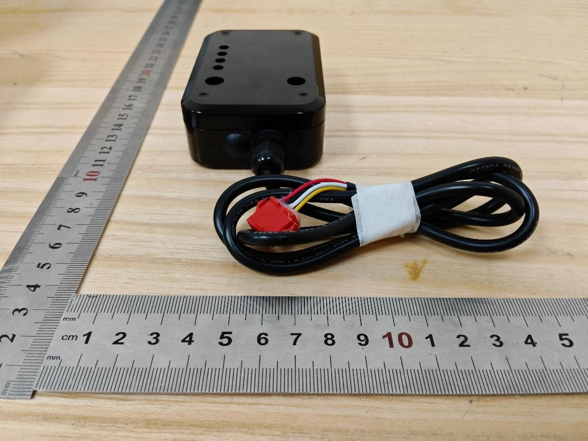
Click to zoom
Application Details
- Equipment Class
- DTS - Digital Transmission System
- Date of Grant
- Sep 11, 2026
- Application Purpose
- Original Equipment
- Equipment Note
- WiFi models
- Frequency Range
- 2412.00000000 - 2462.00000000
- Country
- China
Documents & Files
Document Text
Text extracted from the exhibit documents filed with the FCC. Open a document above to read the original.
Users Manual
INSTALLATION & OPERATION MANUAL Wireless Module Specifications MXL496 Wi-Fi module - technical specifications ItemSpecification Product ModelMXL496 Product DescriptionThis module is used for data transmission and control of heat pump products. Wireless TechnologyIEEE 802.11b/g/n Operating Frequency Band2.412 - 2.484 GHz Modulation Type 802.11b: DQPSK,DBPSK,CCK 802.11g/n: QPSK,BPSK,16QAM,64QAM with OFDM Data Rate 802.11b: 1 / 2 / 5.5 / 11 Mbps 802.11g: 6 / 9 / 12 / 18 / 24 / 36 / 48 / 54 Mbps 802.11n: MCS0 - MCS7, up to 150 Mbps Antenna TypeFPC Antenna Antenna Gain3.0 dBi Power SupplyDC 12 V / 1 A ESP32 Internal Supply VoltageDC 3.3 V (3.0 - 3.6 V) Power Supply Current Peak TX (802.11b, 1 Mbps): 379 mA Average TX (802.11b, 1 Mbps): 239 mA Average RX (802.11b/g/n, 20 MHz): 112 mA Average RX (802.11n, 40 MHz): 118 mA Working Temp (deg C)-40 - +85 deg C Storage Temp (deg C)-40 - +105 deg C FCC Statement This equipment has been tested and found to comply with the limits for a Class B digital device, pursuant to part 15 of the FCC rules. These limits are designed to provide reasonable protection against harmful interference in a residential installation. This equipment generates, uses and can radiate radio frequency energy and, if not installed and used in accordance with the instructions, may cause harmful interference to radio communications. However, there is no guarantee that interference will not occur in a particular installation. If this equipment does cause harmful interference to radio or television reception, which can be determined by turning the equipment off and on, the user is encouraged to try to correct the interference by one or more of the following measures: -Reorient or relocate the receiving antenna. -Increase the separation between the equipment and receiver. -Connect the equipment into an outlet on a circuit different from that to which the receiver is connected. -Consult the dealer or an experienced radio/TV technician for help. This equipment complies with Part 15 of the FCC Rules. Operation is subject to the following two conditions: (1) This device may not cause harmful interference, and (2) This device must accept any interference received, including interference that may cause undesired operation. Any changes or modifications not expressly approved by the party responsible for compliance could void the user’s authority to operate the equipment. changes or modifications not expressly approved by the party responsible for compliance could void the user’s authority to operate the equipment. 2.2 This module has been assessed against the following FCC rule parts: CFR 47 FCC Part 15 C (15.247, DTS). It is applicable to the modular transmitter 2.3 This radio transmitter 2BOGT-MXL496 has been approved by Federal Communications Commission to operate with the antenna types listed below, with the maximum permissible gain indicated. Antenna types not included in this list that have a gain greater than the maximum gain indicated for any type listed are strictly prohibited for use with this device. The concrete contents to check are the following three points. 1) Maximum antenna gains are shown in item 2.7 below. 2) Should be installed so that the end user cannot modify the antenna 3) Feed line should be designed in 50ohm Fine-tuning of return loss etc. can be performed using a matching network. The antenna shall not be accessible for modification or change by the end user. 2.4 The module complies with FCC Part 15.247 and apply for Single module approval. 2.5 Trace antenna designs: Not applicable. This module is intended for use only with approved external FPC antennas. 2.6 This equipment complies with FCC radiation exposure limits set forth for an uncontrolled environment. This equipment should be installed and operated with a minimum distance of 20cm between the radiator & your body. This transmitter must not be co-located or operating in conjunction with any other antenna or transmitter. 2.7 The following antennas have been certified for use with this module. Only antennas of the same type with equal or lower gain may also be used with this module. Other types of antennas and/or higher gain antennas may require the additional authorization for operation. The installer should use unique antenna connector and Antenna types not included in this list that have a gain greater than the maximum gain indicated for any type listed are strictly prohibited for use with this device. The manufacturer of module will inform installer to meet with the FCC part 15.203 in the warning part. Antenna Specification list below: 2.8 Please notice that if the FCC identification number is not visible when the module is installed inside another device, then the outside of the device into which the module is installed must also display a label referring to the enclosed module. This exterior label can use wording such as "Contains FCC ID: 2BOGT-MXL496" ; any similar wording that expresses the same meaning may be used. 2.9 Testing of the host product with all the transmitters installed – referred to as the composite investigation test- is recommended, to verify that the host product meets all the applicable FCC rules. The radio spectrum is to be investigated with all the transmitters in the final host product functioning to determine that no emissions exceed the highest limit permitted for any one individual transmitter as required by Section 2.947(f). The host manufacturer is responsible to ensure that when their product operates as intended it does not have any emissions present that are out of compliance that were not present when the transmitters were tested individually. If the modular transmitter has been fully tested by the module grantee on the required number of channels, modulation types, and modes, it should not be necessary for the host installer to re-test all the available transmitter modes or settings. It is recommended that the host product manufacturer, installing the modular transmitter,…
Text truncated - open the document above for the full version.
Cover Letter(s)
Modular Approval Request FCC (Per 15.212) FCC ID: 2BOGT-MXL496 Items to be covered Answer From Applicant 1.The radio elements of the modular transmitter must have their own shielding. The physical crystal and tuning capacitors may be located external to the shielded radio elements. Yes 2.The modular transmitter must have buffered modulation/data inputs (if such inputs are provided) to ensure that the module will comply with part 15 requirements under conditions of excessive data rates or over-modulation. Yes 3.The modular transmitter must have its own power supply regulation. Yes 4.The modular transmitter must comply with the antenna and transmission system requirements of §§ 15.203, 15.204(b) and 15.204(c). The antenna must either be permanently attached or employ a “unique” antenna coupler (at all connections between the module and the antenna, including the cable). The “professional installation” provision of § 15.203 is not applicable to modules but can apply to limited modular approvals under paragraph (b) of this section. Yes 5.The modular transmitter must be tested in a stand-alone configuration, i.e., the module must not be inside another device during testing for compliance with part 15 requirements. Unless the transmitter module will be battery powered, it must comply with the AC line conducted requirements found in § 15.207. AC or DC power lines and data input/output lines connected to the module must not contain ferrites, unless they will be marketed with the module (see § 15.27(a)). The length of these lines shall be the length typical of actual use or, if that length is unknown, at least 10 centimeters to insure that there is no coupling between the case of the module and supporting equipment. Any accessories, peripherals, or support equipment connected to the module during testing shall be unmodified and commercially available (see § 15.31(i)). Yes 6.The modular transmitter must be equipped with either a permanently affixed label or must be capable of electronically displaying its FCC identification number. (A)If using a permanently affixed label, the modular transmitter must be labeled with its own FCC identification number, and, if the FCC identification number is not visible when the module is installed inside another device, then the outside of the device into which the module is installed must also display a label referring to the enclosed module. This exterior label can use wording such as the following: “Contains Transmitter Module FCC ID: XYZMODEL1” or “Contains FCC ID: XYZMODEL1.” Any similar wording that expresses the same meaning may be used. The Grantee may either provide such a label, an example of which must be included in the application for equipment authorization, or, must provide adequate instructions along with the module which explain this requirement. In the latter case, a copy of these instructions must be included in the application for equipment Yes authorization. (B)If the modular transmitter uses an electronic display of the FCC identification number, the information must be readily accessible and visible on the modular transmitter or on the device in which it is installed. If the module is installed inside another device, then the outside of the device into which the module is installed must display a label referring to the enclosed module. This exterior label can use wording such as the following: “Contains FCC certified transmitter module(s).” Any similar wording that expresses the same meaning may be used. The user manual must include instructions on how to access the electronic display. A copy of these instructions must be included in the application for equipment authorization. 7.The modular transmitter must comply with any specific rules or operating requirements that ordinarily apply to a complete transmitter and the manufacturer must provide adequate instructions along with the module to explain any such requirements. A copy of these instructions must be included in the application for equipment authorization. Yes 8.Radio frequency devices operating under the provisions of this part are subject to the radio frequency radiation exposure requirements specified in §§ 1.1307(b), 1.1310, 2.1091, and 2.1093 of this chapter, as appropriate. Applications for equipment authorization of modular transmitters under this section must contain a statement confirming compliance with these requirements. The modular transmitter must comply with any applicable RF exposure requirements in its final configuration. Technical information showing the basis for this statement must be submitted to the Commission upon request. Yes Note: If compliance with one or more of the numbered requirements, listed above, cannot be demonstrated, it may be possible to obtain a “Limited Modular Approval” (LMA) Emily Jiang Title: engineer Company Name: GUANGDONG PHNIX ECO-ERERGY SOLUTION LTD Date:9/1/2026
External Photos
External Photographs Project No.:4792278599 Page 2 of 4 This report shall not be reproduced except in full, without the written approval of UL Verification Services (Guangzhou) Co., Ltd, Song Shan Lake Branch. View of EUT-1 View of EUT-2 Page 3 of 4 This report shall not be reproduced except in full, without the written approval of UL Verification Services (Guangzhou) Co., Ltd, Song Shan Lake Branch. View of EUT-3 View of EUT-4 Page 4 of 4 This report shall not be reproduced except in full, without the written approval of UL Verification Services (Guangzhou) Co., Ltd, Song Shan Lake Branch. View of EUT-5 View of EUT-6
ID Label/Location Info
Ratings:DC12V;1A FCC ID: 2BOGT-MXL496 This device complies with Part 15 of the FCC Rules. Operation is subject to the following two conditions: (1)this device may not cause harmful interference, and (2) this device must accept any interference received,including interference that may cause undesired operation. 36mm 24mm This label uses a special adhesive and will adhere permanently to the product.
Internal Photos
Internal Photographs Project No.:4792278599 Page 2 of 5 This report shall not be reproduced except in full, without the written approval of UL Verification Services (Guangzhou) Co., Ltd, Song Shan Lake Branch. Internal View of EUT-1 Internal View of EUT-2 Ant Page 3 of 5 This report shall not be reproduced except in full, without the written approval of UL Verification Services (Guangzhou) Co., Ltd, Song Shan Lake Branch. Internal View of EUT-3 Internal View of EUT-4 Page 4 of 5 This report shall not be reproduced except in full, without the written approval of UL Verification Services (Guangzhou) Co., Ltd, Song Shan Lake Branch. Internal View of EUT-5 Internal View of EUT-6 Page 5 of 5 This report shall not be reproduced except in full, without the written approval of UL Verification Services (Guangzhou) Co., Ltd, Song Shan Lake Branch. Internal View of EUT-7
RF Exposure Info
The results reported herein have been performed in accordance with the laboratory’s terms of accreditation. This report shall not be reproduced except in full without the written approval of the Laboratory. The results in this report apply to the test sample(s) mentioned above at the time of the testing period only and are not to be used to indicate applicability to other similar products. FCC RF EXPOSURE REPORT For WiFi models MODEL NUMBER: MXL496 REPORT NUMBER: 4792278599-RF-2 ISSUE DATE: July 7, 2026 FCC ID: 2BOGT-MXL496 Prepared for GUANGDONG PHNIX ECO-ERERGY SOLUTION LTD 3 Tianyuan Road,Dagang Town, Nansha, Guangzhou, Guangdong, China Prepared by UL Verification Services (Guangzhou) Co., Ltd, Song Shan Lake Branch Room 101, Building 2, No.4, Information Road, Songshan Lake, Dongguan, Guangdong, China Tel: +86 769 22038881 Fax: +86 769 33244054 Website: www.ul.com REPORT NO.: 4792278599-RF-2 Page 2 of 7 UL Verification Services (Guangzhou) Co., Ltd, Song Shan Lake Branch FORM No.: 10-SL-F0112 This report shall not be reproduced except in full, without the written approval of UL Verification Services (Guangzhou) Co., Ltd, Song Shan Lake Branch. Revision History Rev. Issue Date Revisions Revised By V0 July 7, 2026 Initial Issue REPORT NO.: 4792278599-RF-2 Page 3 of 7 UL Verification Services (Guangzhou) Co., Ltd, Song Shan Lake Branch FORM No.: 10-SL-F0112 This report shall not be reproduced except in full, without the written approval of UL Verification Services (Guangzhou) Co., Ltd, Song Shan Lake Branch. TABLE OF CONTENTS 1. ATTESTATION OF TEST RESULTS ................................................................................. 4 2. TEST METHODOLOGY ..................................................................................................... 5 3. FACILITIES AND ACCREDITATION ................................................................................. 5 4. REQUIREMENT ................................................................................................................. 6 REPORT NO.: 4792278599-RF-2 Page 4 of 7 UL Verification Services (Guangzhou) Co., Ltd, Song Shan Lake Branch FORM No.: 10-SL-F0112 This report shall not be reproduced except in full, without the written approval of UL Verification Services (Guangzhou) Co., Ltd, Song Shan Lake Branch. 1. ATTESTATION OF TEST RESULTS Applicant Information Company Name: GUANGDONG PHNIX ECO-ERERGY SOLUTION LTD Address: 3 Tianyuan Road,Dagang Town, Nansha, Guangzhou, Guangdong, China Manufacturer Information Company Name: GUANGDONG PHNIX ECO-ERERGY SOLUTION LTD Address: 3 Tianyuan Road,Dagang Town, Nansha, Guangzhou, Guangdong, China EUT Information EUT Name: WiFi models Model: MXL496 Brand: PHNIX Sample Received Date: June 15, 2026 Sample Status: Normal Sample ID: 9840977 Date of Tested: June 16, 2026 to July 7, 2026 APPLICABLE STANDARDS STANDARD TEST RESULTS 447498 D04 Interim General RF Exposure Guidance v01 PASS Prepared By: Checked By: James Qin Kebo Zhang Senior Project Engineer Operations Leader Approved By: Stephen Guo Operations Manager REPORT NO.: 4792278599-RF-2 Page 5 of 7 UL Verification Services (Guangzhou) Co., Ltd, Song Shan Lake Branch FORM No.: 10-SL-F0112 This report shall not be reproduced except in full, without the written approval of UL Verification Services (Guangzhou) Co., Ltd, Song Shan Lake Branch. 2. TEST METHODOLOGY The tests documented in this report were performed in accordance with 47 CFR FCC Part 1 Subpart I, section 1.1307 and KDB 447498 D04 Interim General RF Exposure Guidance v01. 3. FACILITIES AND ACCREDITATION Accreditation Certificate A2LA (Certificate No.: 4102.01) UL Verification Services (Guangzhou) Co., Ltd. Song Shan Lake Branch. has been assessed and proved to be in compliance with A2LA. FCC (FCC Designation No.: CN1187) UL Verification Services (Guangzhou) Co., Ltd. Song Shan Lake Branch. Has been recognized to perform compliance testing on equipment subject to the Commission's Declaration of Conformity (DoC) and Certification rules. ISED (Company No.: 21320) UL Verification Services (Guangzhou) Co., Ltd. Song Shan Lake Branch. has been registered and fully described in a report filed with ISED. The Company Number is 21320 and the test lab Conformity Assessment Body Identifier (CABID) is CN0046. VCCI (Registration No.: C-20202, G-20240, R-20248 and T-20202) UL Verification Services (Guangzhou) Co., Ltd. Song Shan Lake Branch. has been assessed and proved to be in compliance with VCCI, the Membership No. is 3793. Facility Name: Chamber E, the VCCI registration No. is G-20240 and R-20248 Shielding Room F, the VCCI registration No. is C-20202 and T-20202 Note 1: All tests measurement facilities use to collect the measurement data are located at Room 101, Building 2, No.4, Information Road, Songshan Lake, Dongguan, Guangdong, China. REPORT NO.: 4792278599-RF-2 Page 6 of 7 UL Verification Services (Guangzhou) Co., Ltd, Song Shan Lake Branch FORM No.: 10-SL-F0112 This report shall not be reproduced except in full, without the written approval of UL Verification Services (Guangzhou) Co., Ltd, Song Shan Lake Branch. 4. REQUIREMENT LIMIT AND CALCULATION METHOD According to 447498 D04 Interim General RF Exposure Guidance v01, 2.1.4 MPE-Based Exemption An alternative to the SAR-based exemption is provided in § 1.1307(b)(3)(i)(C), for a much wider frequency range, from 300 kHz to 100 GHz, applicable for separation distances greater or equal to λ/2π, where λ is the free-space operating wavelength in meters. The MPE-based test exemption condition is in terms of ERP, defined as the product of the maximum antenna gain and the delivered maximum time-averaged power.10 For this case, a RF source is an RF exempt device if its ERP (watts) is no more than a frequency-dependent value, as detailed tabular form in Appendix B. These limits have been derived based on the basic specifications on Maximum Permissible Exposure (MPE) considered for the FCC rules in § 1.1310(e)(1). MPE-based Exempt…
Text truncated - open the document above for the full version.
Test Report
The results reported herein have been performed in accordance with the laboratory’s terms of accreditation. This report shall not be reproduced except in full without the written approval of the Laboratory. The results in this report apply to the test sample(s) mentioned above at the time of the testing period only and are not to be used to indicate applicability to other similar products. FCC 47 CFR PART 15 SUBPART C TEST REPORT For WiFi models MODEL NUMBER: MXL496 REPORT NUMBER: 4792278599-RF-1 ISSUE DATE: July 7, 2026 FCC ID: 2BOGT-MXL496 Prepared for GUANGDONG PHNIX ECO-ERERGY SOLUTION LTD 3 Tianyuan Road,Dagang Town, Nansha, Guangzhou, Guangdong, China Prepared by UL Verification Services (Guangzhou) Co., Ltd, Song Shan Lake Branch Room 101, Building 2, No.4, Information Road, Songshan Lake, Dongguan, Guangdong, China Tel: +86 769 22038881 Fax: +86 769 33244054 Website: www.ul.com REPORT NO.: 4792278599-RF-1 Page 2 of 127 UL Verification Services (Guangzhou) Co., Ltd, Song Shan Lake Branch FORM NO: 10-SL-F0035 This report shall not be reproduced except in full, without the written approval of UL Verification Services (Guangzhou) Co., Ltd, Song Shan Lake Branch. Revision History Rev. Issue Date Revisions Revised By V0 July 7, 2026 Initial Issue REPORT NO.: 4792278599-RF-1 Page 3 of 127 UL Verification Services (Guangzhou) Co., Ltd, Song Shan Lake Branch FORM NO: 10-SL-F0035 This report shall not be reproduced except in full, without the written approval of UL Verification Services (Guangzhou) Co., Ltd, Song Shan Lake Branch. Summary of Test Results Test Item Clause Limit/Requirement Result Antenna Requirement N/A FCC Part 15.203/15.247 (c) Pass (NOTE 1) AC Power Line Conducted Emission ANSI C63.10-2020, Clause 6.2 FCC Part 15.207 Pass Conducted Output Power ANSI C63.10-2020, Clause 11.9.1.2 FCC Part 15.247 (b)(3) Pass 6dB Bandwidth and 99% Occupied Bandwidth ANSI C63.10-2020, Clause 11.8.1 FCC Part 15.247 (a)(2) Pass Power Spectral Density ANSI C63.10-2020, Clause 11.10.2 FCC Part 15.247 (e) Pass Conducted Band edge and spurious emission ANSI C63.10-2020, Clause 11.11 FCC Part 15.247(d) Pass Radiated Band edge and Spurious Emission ANSI C63.10-2020, Clause 11.12 FCC Part 15.247 (d) FCC Part 15.205/15.209 Pass Duty Cycle ANSI C63.10-2020, Clause 11.6 None; for reporting purposes only. Pass Note: 1. For FCC, this report is also performed according to ANSI C63.10-2020 + Cor.1-2023. *This test report is only published to and used by the applicant, and it is not for evidence purpose in China. *The measurement result for the sample received is <Pass> according to <FCC 47 CFR PART 15 SUBPART C> when <Simple Acceptance> decision rule is applied. Decision rule for statement of conformity: The measurement uncertainty is not taken into account for statement of conformity. REPORT NO.: 4792278599-RF-1 Page 4 of 127 UL Verification Services (Guangzhou) Co., Ltd, Song Shan Lake Branch FORM NO: 10-SL-F0035 This report shall not be reproduced except in full, without the written approval of UL Verification Services (Guangzhou) Co., Ltd, Song Shan Lake Branch. CONTENTS 1. ATTESTATION OF TEST RESULTS ..................................................................................... 6 2. TEST METHODOLOGY ......................................................................................................... 7 3. FACILITIES AND ACCREDITATION ..................................................................................... 7 4. CALIBRATION AND UNCERTAINTY ................................................................................... 8 4.1. MEASURING INSTRUMENT CALIBRATION ........................................................... 8 4.2. MEASUREMENT UNCERTAINTY ............................................................................ 8 5. EQUIPMENT UNDER TEST .................................................................................................. 9 5.1. DESCRIPTION OF EUT ........................................................................................... 9 5.2. CHANNEL LIST ...................................................................................................... 10 5.3. MAXIMUM POWER ................................................................................................ 10 5.4. TEST CHANNEL CONFIGURATION ...................................................................... 10 5.5. THE WORSE CASE POWER SETTING PARAMETER .......................................... 11 5.6. DESCRIPTION OF AVAILABLE ANTENNAS ......................................................... 12 5.7. SUPPORT UNITS FOR SYSTEM TEST ................................................................. 12 6. MEASURING EQUIPMENT AND SOFTWARE USED......................................................... 14 7. ANTENNA PORT TEST RESULTS ..................................................................................... 17 7.1. CONDUCTED OUTPUT POWER ........................................................................... 17 7.2. 6DB BANDWIDTH AND 99% OCCUPIED BANDWIDTH ........................................ 18 7.3. POWER SPECTRAL DENSITY .............................................................................. 20 7.4. CONDUCTED BAND EDGE AND SPURIOUS EMISSION ..................................... 22 7.5. DUTY CYCLE ......................................................................................................... 24 8. RADIATED TEST RESULTS ............................................................................................... 25 8.1. RESTRICTED BANDEDGE .................................................................................... 32 8.2. SPURIOUS EMISSIONS(1 GHZ~3 GHZ) ............................................................... 50 8.3. SPURIOUS EMISSIONS(3 GHZ~18 GHZ) ............................................................. 56 8.4. SPURIOUS EMISSIONS(9 KHZ~30 MHZ) ............................................................. 80 8.5. SPURIOUS EMISSIONS(1…
Text truncated - open the document above for the full version.
Test Report
GuangzhouXianjuintelligenttechnologyco .,Ltd 045WIFI 2.4G aerial antenna SD-045WIFI 2.4-FPC Prepared by: Zeng Xiaofeng Reviewed by: Zhan Chenjie Date: 2026.06.23 Building 3, No. 68 Nanxiang 1st Road, Huangpu, Guangzhou Email:[email protected] TEL: 0755-86006322 FAX: 18929599312 ShenzhenShuodianElectronicTechnologyCo.,Ltd GuangzhouXianjuintelligenttechnologyco. ,Ltd The operating temperature range for this product is -20 to +65°C. NO.ITEMSDETAILS 1 model 2.4 GWIFI 2 Frequency band 2400MHz-2500MHz 3VSWR≤2.0 4Gain≥2.0dBi 5RadiationEfficiency≥50% 6 impedance 50Ω 7 Antenna TypeFPC antenna 8 Antenna implementation form FPC + 1.13 Coaxial Cable 9 Antenna images ShenzhenShuodianElectronicTechnologyCo.,Ltd Date :2014 -6-30 Page number6-8 GuangzhouXianjuintelligenttechnologyco. ,Ltd Product Drawings: ShenzhenShuodianElectronicTechnologyCo.,Ltd Date :2014 -6-30 Page number7-8 GuangzhouXianjuintelligenttechnologyco. ,Ltd Testing Environment and Equipment Test environment: temperature: 10°C——+30°C Relative humidity:≤80%(+40°C) Atmospheric pressure:750mmkg±30mmkg Testing equipment: Network analyzer KEYSIGHT E5071C Multi-probe Microwave Anechoic Chamber 4.22.1 Product electrical performance test data: S11: Marker(MHZ )240024502500 Returnloss-11-18-13.8 VSWR1.71.31.5 Shenzhen Shuodian Electronic Technology Co.,Ltd Date:2014-6-30 Page number 8-8 Guangzhou Xianju intelligent technology co.,Ltd 4.22.2 antenna gain: frequency(MHz) 24002410242024302440245024602470248024902500 Gain(dBi) 2.662.893.002.602.712.622.902.822.723.073.35 Efficient(%) 54.9356.0560.1060.9566.7966.4268.9367.3268.1869.3770.22 Test setup photo ShenzhenShuodianElectronicTechnologyCo.,Ltd Date :2014 -6-30 Page number9-8 GuangzhouXianjuintelligenttechnologyco. ,Ltd Antenna radiation pattern: 2450MHZ
Test Setup Photos
Appendix II Setup Photographs Project No.:4792278599 Page 2 of 5 This report shall not be reproduced except in full, without the written approval of UL Verification Services (Guangzhou) Co., Ltd, Song Shan Lake Branch. AC Power Line Conducted Emission Page 3 of 5 This report shall not be reproduced except in full, without the written approval of UL Verification Services (Guangzhou) Co., Ltd, Song Shan Lake Branch. Radiated Band edge and Spurious Emission RADIATED RF MEASUREMENT SETUP (ABOVE 1 GHz) MEASUREMENT POSITION MEASUREMENT POSITION (X axis) Page 4 of 5 This report shall not be reproduced except in full, without the written approval of UL Verification Services (Guangzhou) Co., Ltd, Song Shan Lake Branch. MEASUREMENT POSITION (Y axis) MEASUREMENT POSITION (Z axis) Page 5 of 5 This report shall not be reproduced except in full, without the written approval of UL Verification Services (Guangzhou) Co., Ltd, Song Shan Lake Branch. RADIATED RF MEASUREMENT SETUP (30MHz~1GHz) RADIATED RF MEASUREMENT SETUP (Below 30MHz)
Contact Information
Applicant
Emily Jiang
[email protected]Fax: 020-39067773
Technical Contact
Americas Compliance Consulting LLC dba iCertifiPaul Preston
5809 US-2, Suite B, Albeni Plaza · Priest River, 83856 · United States
Test Firm
UL Verification Services (Guangzhou) Co., Ltd.Stephen Guo
Technical Specifications
| # | Rule Parts | Frequency Range | Power Output |
|---|---|---|---|
| 1 | 15C | 2.41 GHz - 2.46 GHz | 64.00 mW |