2BOTM-88877788The IotaComm Environmental Sensor wireless monitor.
IotaComm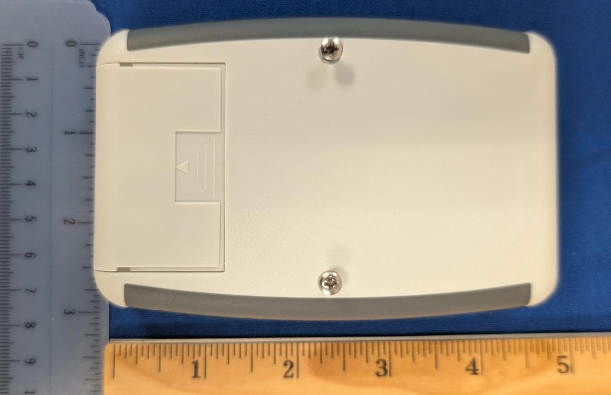
Click to zoom
Application Details
- Equipment Class
- TNB - Licensed Non-Broadcast Station Transmitter
- Date of Grant
- Jan 22, 2026
- Application Purpose
- Original Equipment
- Equipment Note
- The IotaComm Environmental Sensor wireless monitor.
- Frequency Range
- 809.00000000 - 817.00000000
- Company
- IotaComm
- Country
- United States
Documents & Files
Document Text
Text extracted from the exhibit documents filed with the FCC. Open a document above to read the original.
Users Manual
1 IotaComm 800 MHz IAQ Sensor User Manual 2 Table of Contents 1. Introduction ............................................................................................................ 3 1.1 About This Manual ........................................................................................... 3 1.2 Product Overview ............................................................................................. 3 2. Safety and Handling Instructions ................................................................................ 3 3. Hardware Overview ................................................................................................. 4 3.1 Package Contents ............................................................................................. 4 3.2 Sensor Indicators .............................................................................................. 4 4. Installation .............................................................................................................. 4 4.1 Recommended Installation Locations................................................................... 4 4.2 Mounting Options ............................................................................................. 5 4.2.1 Option 1: Wall Mount (Screw Fixing) .............................................................. 5 Option 2: Adhesive Mount (3M Tape) ......................................................................... 5 5. Power Supply & Battery Replacement ......................................................................... 5 6. Telemetry and Data Collection ................................................................................... 6 7. Operating Guidelines ................................................................................................ 7 8. Declaration of Conformity and FCC Statements ............................................................ 8 9. Customer Support .................................................................................................. 10 3 1. Introduction 1.1 About This Manual This user manual is intended to provide an overview of the IotaComm 800 MHz Licensed LoRaWAN Indoor Air Quality (IAQ) Sensor ("IotaComm 800 MHz IAQ Sensor"). It explains the sensor's functionality, installation options, key telemetry parameters, battery replacement instructions, and support contact information. Note: The IotaComm 800 MHz IAQ Sensor is designed to be part of a fully managed IAQ service delivered by IotaComm and its partners. The product will be deployed, supported, and maintained by IotaComm or authorized partners. Customers are not required to interact with, operate, or maintain the sensor directly. 1.2 Product Overview The IotaComm 800 MHz IAQ Sensor provides continuous indoor environmental quality monitoring over IotaComm's 800 MHz licensed LoRaWAN network. The sensor collects and transmits real-time data on: • Temperature • Relative Humidity • Barometric Pressure • Total Volatile Organic Compounds (TVOCs) The sensor's gas sensor detects and estimates levels of key VOCs, including: • Ethane • Isoprene (2-methyl-1,3-butadiene) • Ethanol • Acetone • Carbon Monoxide 2. Safety and Handling Instructions • Do not attempt to open, disassemble, or modify the sensor. 4 • Do not expose the sensor to liquids, extreme temperatures, or direct flames. • Replace batteries only as described in this manual. • The sensor is intended for indoor use only. 3. Hardware Overview 3.1 Package Contents • 1 × IotaComm 800 MHz IAQ Sensor • 1 × Mounting Bracket • 1 × 3M Double-Sided Tape • 3 × Wall Mounting Kits • 1 × Theft-Deterring Screw • 4 × ER14505 Li-SOCl2 Batteries (Pre-installed) • 1 × Quick Start Guide • 1 × Warranty Card 3.2 Sensor Indicators The sensor has onboard LED indicators to display operational status, network connectivity, and air quality alerts. 4. Installation 4.1 Recommended Installation Locations The sensor should be installed: • Indoors, away from heat sources and airflow obstructions. • At least 1.5 meters above floor level. • Away from direct sunlight, windows, or vents. 5 4.2 Mounting Options 4.2.1 Option 1: Wall Mount (Screw Fixing) 1. Secure the mounting bracket to the wall using the included screws and wall plugs. 2. Attach the sensor to the bracket and secure it with the theft- deterring screw. Option 2: Adhesive Mount (3M Tape) 1. Apply the provided double-sided tape to the back of the mounting bracket. 2. Press the bracket firmly against a clean, flat wall surface. 3. Attach the sensor to the bracket and secure it. 5. Power Supply & Battery Replacement The sensor is powered by 2 standard double AA batteries. To replace batteries: 1. Remove the theft-deterring screw and open the back cover. 2. Remove old batteries and insert two new double AA batteries. 3. Ensure correct polarity alignment. 4. Replace the back cover and secure it with the screw. Battery Precautions: • Always use the specified battery type. • Replace all batteries at the same time. • Do not mix old and new batteries. 6 6. Telemetry and Data Collection The sensor collects and transmits the following environmental data: Parameter Measurement Unit Temperature °C Humidity % RH Barometric Pressure hPa Gas Resistance (VOC Index) Ohms VOC Detection: The sensor detects the following volatile organic compounds (VOCs): • Ethane • Isoprene / 2-methyl-1,3 Butadiene • Ethanol • Acetone • Carbon Monoxide VOC data is used to calculate an Air Quality Index (IAQ) score, providing an indication of overall indoor air quality. 7 7. Operating Guidelines The sensor is part of IotaComm's managed service offering. Customers do not need to configure, maintain, or directly access the sensor. All configuration, calibration, and maintenance activities will be performed by IotaComm or authorized partners. If customers or partners encounter any issues with the sensor, they should contact IotaComm Customer Service. 8 8. Declaration of Conformity and FCC Statements The sens…
Text truncated - open the document above for the full version.
Attestation Statements
600 HAMILTON ST, SUITE 1010, ALLENTOWN, PA 18101 • [email protected] • TOLL-FREE: 1-855-743-6478 Attention: Application Examiner Re: Certification designating a U.S. agent for service of process pursuant to 47 CFR part §2.911(d)(7) of the FCC rules To whom it may concern, This letter is to certify that IotaComm (“Applicant”) accepts responsibilities to act as its own agent pursuant to 47 CFR part §2.911(d)(7) of the FCC rules for service of process. I consent to the obligation to accept service of process on behalf of the applicant in regard to the FCC ID designated below. I HEREBY CERTIFY THAT I am authorized to make the representations above on behalf of the Applicant. I further acknowledge the requirement to maintain an agent extends for no less than one year after the termination of all marketing and importation or the conclusion of and commission-related proceeding involving the equipment and agree to immediately notify the FCC and Intertek if there is any change in the status identified above. Applicant Company Name : IotaComm Contact Name : Wael Guibene Address : 200 W Franklin St #300, Chapel Hill, NC 27516 Telephone No : 805-668-5234 Email : [email protected] FCC ID : 2BOTM-88877788 Applicant FRN : 0028957371 Signature: Date: April 28, 2025
Attestation Statements
600 HAMILTON ST, SUITE 1010, ALLENTOWN, PA 18101 • [email protected] • TOLL-FREE: 1-855-743-6478 12/10/2025 Attention: Application Examiner Re: Covered List, located at https://www.fcc.gov/supplychain/coveredlist and 47 CFR parts §2.903 and §2.911(d)(5)(ii) of the FCC rules Applicant: IotaComm FCC ID: 2BOTM-88877788 To whom it may concern, IotaComm, (“Applicant”) certifies that the equipment for which authorization is sought is not “covered” equipment prohibited from receiving an equipment authorization pursuant to 47 CFR part §2.903 of the FCC rules and does not originate directly or indirectly from any company named on the covered list located in the link above or any subsidiary or affiliate thereof. Applicant further certifies that, as of the date of the filing of the application, the Applicant is not identified on the Covered List as an entity producing “covered” equipment and is not a subsidiary or affiliate of any such entity pursuant to 47 CFR part §1.50002 and required by 47 CFR part §2.911(d)(5)(ii) of the FCC rules. Applicant further certifies that no Cybersecurity or anti-virus software produced or provided by Kaspersky Lab, Inc. or any of its successors and assignees, including equipment with integrated Kaspersky Lab, Inc. (or any of its successors and assignees) cybersecurity or anti-virus software is installed in the equipment being certified. I HEREBY CERTIFY THAT I am authorized to make the representations above on behalf of the Applicant and agree to immediately notify Intertek if there is any change in the status identified above. Wael Guibene SVP, Product and Technology IotaComm 12/10/2025
Cover Letter(s)
600 HAMILTON ST, SUITE 1010, ALLENTOWN, PA 18101 • [email protected] • TOLL-FREE: 1-855-743-6478 12/10/2025 Attention: Application Examiner Re: Request for confidentiality Applicant: IotaComm FCC ID: 2BOTM-88877788 To whom it may concern, Permanent Confidentiality Request is hereby submitted by IotaComm to withhold permanently from public review certain portions of the application for equipment certification for the referenced FCC identifiers. This request for confidentiality is made pursuant to 47 CFR 0.457(d) and 0.459 of the FCC Rules. In particular, the following sections of the application are to be kept permanently confidential: • Schematics • Detailed Block diagrams • Detailed Operational/Functional Description • Tune up procedure • Parts list Rationale for request for confidentiality: IotaComm has invested considerable time and materials in research and development to produce the referenced product. Permanent confidentiality: Disclosure of the permanently confidential portions of this application to competitors would not only give them significant competitive advantages in developing similar products, but would also disclose successful implementation of unpublished, leading-edge technology developed by us. Wael Guibene SVP, Product and Technology IotaComm
Cover Letter(s)
600 HAMILTON ST, SUITE 1010, ALLENTOWN, PA 18101 • [email protected] • TOLL-FREE: 1-855-743-6478 12/10/2025 Intertek Testing Services NA Ltd. 70 Codman Hill Road Boxborough, MA 01719 Subject: Limited Agency Agreement IotaComm FCC ID: 2BOTM-88877788 To Whom It May Concern: We, IotaComm, hereby authorized Darin Hatcher of Connected Development to act as our Agent for the purpose of preparing application for FCC ID number 2BOTM-88877788 under all applicable parts of the FCC rules and regulations. The effective date of this limited agency agreement is January 22, 2025. The Limited Agency Agreement expires on January 22, 2026, unless sooner terminated or extended by written notice to Intertek Testing Services and the Federal Communications Commission. This is to advise that we are in full compliance with the Anti-Drug Abuse Act. The applicant is not subject to a denial of federal benefits pursuant to Section 5301 of the Anti-Drug Act of 1988, 21 U.S.C. 862, and no party to the application is subject to a denial of federal benefits pursuant to that section. If you have any questions or comments, please do not hesitate to contact me. Sincerely, Wael Guibene SVP, Product and Technology Cell: 805-668-5234
External Photos
External Photos Top: Bottom: Side 1: Side 2: End 1: End 2:
ID Label/Location Info
Label: Label Location:
Internal Photos
Internal Photos PCB top with shield: PCB bottom: PCB top without shield:
RF Exposure Info
Iota Networks, LLC. RF Exposure Exhibit SCOPE OF WORK EMC TESTING – IotaComm, Model: 800CD-HW REPORT NUMBER 105602545MPK-003 ISSUE DATE April 20, 2025 REVISED DATE N/A PAGES 10 DOCUMENT CONTROL NUMBER Non-Specific Radio Report Shell Rev. December 2017 MPK © 2017 INTERTEK Non-Specific Radio Report Shell Rev. December 2017 MPK EMC Report for Iota Networks, LLC. on the IotaComm, Model Number: 800CD-HW Page 2 of 10 RF Exposure Exhibit (Mobile Devices) Report Number: 105602545MPK-003 Project Number: G105602545 Report Issue Date: May 12, 2025 Testing performed on the IotaComm Model Tested: 800CD-HW FCC ID: 2BOTM-88877788 to 47CFR 2.1091 for Iota Networks, LLC. Tested by: Client: Intertek 1365 Adams Court Menlo Park, CA 94025 USA Iota Networks, LLC. 600 Hamilton St., Suite 1010 Allentown PA, 18101 USA Report prepared by: Report reviewed by: Arjun Mukherjea / EMC Engineer Aaron Chang / EMC Team Leader This report is for the exclusive use of Intertek's Client and is provided pursuant to the agreement between Intertek and its Client. Intertek's responsibility and liability are limited to the terms and conditions of the agreement. Intertek assumes no liability to any party, other than to the Client in accordance with the agreement, for any loss, expense or damage occasioned by the use of this report. Only the Client is authorized to permit copying or distribution of this report and then only in its entirety. Any use of the Intertek name or one of its marks for the sale or advertisement of the tested material, product or service must first be approved in writing by Intertek. The observations and test results in this report are relevant only to the sample tested. This report by itself does not imply that the material, product, or service is or has ever been under an Intertek certification program. This report must not be used to claim product endorsement by A2LA, NIST nor any other agency of the U.S. Government. REPORT NUMBER: 105602545MPK-003 Issued: May 12, 2025 Non-Specific Radio Report Shell Rev. December 2017 MPK EMC Report for Iota Networks, LLC. on the IotaComm, Model Number: 800CD-HW Page 3 of 10 Report No. 105602545MPK-003 Equipment Under Test: IotaComm Model Number: 800CD-HW Applicant: Iota Networks, LLC. Contact: Derek Wallace Address: Iota Networks, LLC. 600 Hamilton St., Suite 1010 Allentown PA, 18101 Country: USA Tel. Number: (612) 590-7807 Email: [email protected] Applicable Regulation: 47CFR 2.1091 We attest to the accuracy of this report: Arjun Mukherjea EMC Engineer Aaron Chang EMC Team Leader REPORT NUMBER: 105602545MPK-003 Issued: May 12, 2025 Non-Specific Radio Report Shell Rev. December 2017 MPK EMC Report for Iota Networks, LLC. on the IotaComm, Model Number: 800CD-HW Page 4 of 10 TABLE OF CONTENTS Mizuho Orthopedic Systems Inc. .................................................................. Error! Bookmark not defined. 1.0 RF Exposure Summary.................................................................................................................. 5 2.0 RF Exposure Limits ....................................................................................................................... 5 3.0 Test Results .................................................................................................................................... 6 4.0 Variant Models ................................................................................................................................ 7 5.0 Document History .......................................................................................................................... 8 Appendix A: Power Density Calculation ................................................................................................... 9 REPORT NUMBER: 105602545MPK-003 Issued: May 12, 2025 Non-Specific Radio Report Shell Rev. December 2017 MPK EMC Report for Iota Networks, LLC. on the IotaComm, Model Number: 800CD-HW Page 5 of 10 1.0 RF Exposure Summary Test Reference FCC Result Radio frequency Radiation Exposure Evaluation 47 CFR§2.1091 Complies 2.0 RF Exposure Limits In this document, we evaluate the RF Exposure to human body due the intentional transmission from the transmitter (EUT). The limits for Maximum Permissible Exposure (MPE) specified in FCC 1.1310 are followed. 2.1 FCC Limits According to FCC 1.1310 table 1: The criteria listed in the following table shall be used to evaluate the environmental impact of human exposure to radio-frequency (RF) radiation as specified in 1.1307(b) LIMITS FOR MAXIMUM PERMISSIBLE EXPOSURE (MPE) Frequency Range (MHz) Electric Field Strength (V/m) Magnetic Field Strength (A/m) Power Density (mW/cm 2 ) Average Time (minutes) (A)Limits For Occupational / Control Exposures 0.3 – 3.0 614 1.63 *100 6 3.0 – 30 1842/f 4.89/f *900/f 2 6 30-300 61.4 0.163 1.0 6 300 - 1500 ... ... F/300 6 1500 - 100,000 ... ... 5 6 (B)Limits For General Population / Uncontrolled Exposure 0.3 – 1.34 614 1.63 *100 30 1.34 – 30 824/f 2.19/f *180/f 2 30 30 – 300 27.5 0.073 0.2 30 300 - 1500 ... ... F/1500 30 1500 - 100,000 ... ... 1.0 30 F = Frequency in MHz * = plane wave equivalent density REPORT NUMBER: 105602545MPK-003 Issued: May 12, 2025 Non-Specific Radio Report Shell Rev. December 2017 MPK EMC Report for Iota Networks, LLC. on the IotaComm, Model Number: 800CD-HW Page 6 of 10 3.0 Test Results 3.1 Classification Radio is installed inside a mobile host device. The antenna of the product, under normal use condition, is at least 20 cm away from the body of the user and accessible to the end user. Warning statement to the user for keeping at least 20 cm or more separation distance with the antenna should be included in user’s manual. 3.2 EIRP calculations The table in the IotaComm, Model: 800CD-HW consists of one radio: 809.1025MHz – 816.9875MHz F1D/FSK Modulation. 3.3 Maximum RF Power Specification of Radios on the 800CD-HW Location Table Type 1 F1D / FSK Modulation Frequency Range 809.1025 – 816.9875MHz Antenna Rated RF…
Text truncated - open the document above for the full version.
Test Report
Product Specification SR4C033-PS-1.0 Page 1 1. Features Antenna for LP-WAN applications. Including NB-IOT, LoRa, SigFox, ISM and Weightless-P Frequency bands from 791- 960MHz Maintains high performance on device: DFI (Designed for Integration) Corner placement to save space Low profile innovative design. SMD mounting Supplied on Tape and Reel Automotive temperature rating. 2. Description Latona uses a ground plane on the host PCB to radiate effectively. The antenna itself requires a clearance underneath. An external matching circuit is used to optimise the antenna within a device to the required bands. Designed specifically for LP-WAN applications that require a small robust solution. Latona comes in Left and Right hand versions to optimise placement. 3. Applications Remote monitoring/ Smart meters Network Devices Smart Buildings Smart cities Manufacturing automation Agriculture/Environment Consumer tracking Latona Antenna for LP-WAN applications Part No. SR4C033-L SR4C033-R lamiiANT ® Product Specification Antennas for Wireless M2M Applications Latona Part No. SR4C033 Antennas for Wireless M2M Applications Product Specification SR4C033-PS-1.0 Page 2 4. Part Number Latona Left: SR4C033-L Latona Right: SR4C033-R 5. General Data 6. RF Characteristics Product name Latona Part Number SR4C033 Frequency 791 – 960MHz Polarization Linear Operating temperature -40°C to140°C Environmental Condition Test ISO16750-4 5.1.1.1/5.1.2.1/5.3.2 Impedance with matching 50 Ω Weight < 2g Antenna type SMD Dimensions 20.0 x 11.0 x 1.6 (mm) 791 – 862 MHz 824 – 960 MHz Peak gain 0.5dBi 0.8dBi Average gain (Linear) -1.50dBi -1.50dBi Average efficiency >60% >65% Maximum return loss -9dB -7dB Maximum VSWR 2.1:1 2.6:1 All data measured on Antenova’s evaluation PCB Part No. SR4C033-EVB-1 Latona Part No. SR4C033 Antennas for Wireless M2M Applications Product Specification SR4C033-PS-1.0 Page 3 7. RF Performance The performance is shown for two tuned variants (Tuning dependant on required band). Matching circuit is used for band selection. B20: 791 – 862MHz B5 and B8: 824-894MHz; 880- 960MHz 7.1 Return Loss 7.2 VSWR Latona Part No. SR4C033 Antennas for Wireless M2M Applications Product Specification SR4C033-PS-1.0 Page 4 7.3 Antenna pattern 7.3.1 791 – 862 MHz 3D pattern at 830 MHz Drag to rotate pattern and PCB by using Adobe Reader (Click to Activate) Latona Part No. SR4C033 Antennas for Wireless M2M Applications Product Specification SR4C033-PS-1.0 Page 5 7.3.2 824 – 960 MHz 3D pattern at 880 MHz Drag to rotate pattern and PCB by using Adobe Reader (Click to Activate) Latona Part No. SR4C033 Antennas for Wireless M2M Applications Product Specification SR4C033-PS-1.0 Page 6 8. Antenna Dimensions Latona Left: SR4C033-L Latona Right: SR4C033-R L W H Length Width Height 20.0 ±0.1 11.0 ±0.1 1.6 ±0.1 All Dimensions in (mm) Top side Bottom Side All Dimensions in (mm) 1 2 3 4 5 6 7 6 8 6 9 6 9 6 8 6 7 6 6 5 4 3 2 1 Latona Part No. SR4C033 Antennas for Wireless M2M Applications Product Specification SR4C033-PS-1.0 Page 7 9.0 Schematic symbol and Pin definition The circuit symbol for the antenna is shown below. The antenna has 9 pins with only two as functional. All other pins are for mechanical strength. 10.0 Antenna footprint The recommended host PCB footprint is below. 9 copper pads all 1.8 x 1.3 (mm) All Dimensions in mm Pin Description 2 Feed 1 Band Select (B.SEL) 3,4,5,6,7,8,9 Not used (Mechanical only) Latona Part No. SR4C033 Antennas for Wireless M2M Applications Product Specification SR4C033-PS-1.0 Page 8 11. Electrical Interface 11.1 Transmission Line All transmission lines should be designed to have a characteristic impedance of 50Ω. • The length of the transmission lines should be kept to a minimum. • Any other parts of the RF system like transceivers, power amplifiers, etc, should also be designed to have an impedance of 50 Ω. Once the material for the PCB has been chosen (PCB thickness and dielectric constant), a coplanar transmission line can easily be designed using any of the commercial software packages for transmission line design. For the chosen PCB thickness, copper thickness and substrate dielectric constant, the program will calculate the appropriate transmission line width and gaps on either side of the track so the characteristic impedance of the co-planar transmission is 50 Ω. 11.2 Matching Circuit The antenna requires a matching circuit that must be optimized for each product. The matching circuit will require up to five components and the following circuit should be designed into the host PCB. Not all components may be required but should be included as a precaution. The matching network must be placed close to the antenna feed to ensure it is more effective in tuning the antenna. Latona Part No. SR4C033 Antennas for Wireless M2M Applications Product Specification SR4C033-PS-1.0 Page 9 12.0 Antenna Integration Guide 12.1 Antenna Placement Whatever the size of the host PCB, the antenna should ideally be placed on the host PCB’s shortest side, in the corner. The left / right antennas are placed in the corresponding corner of the PCB: SR4C033-L (Left Corner) and SR4C033-R (Right Corner). 12.2 Host PCB Layout The footprint and clearance on the host PCB must meet the antenna specification. An example of the PCB layout shows the antenna footprint with clearance. The feed (Pin 2) connects to the matching circuit close to the antenna. For Pin 1 (B.SEL) the component should be close to this pin. Example host layout 1 Latona Part No. SR4C033 Antennas for Wireless M2M Applications Product Specification SR4C033-PS-1.0 Page 10 12.3 Host PCB Clearance Below shows the antenna footprint and clearance through all layers on the PCB. Only the antenna pads and connections to feed and GND are present within this clearance area. The clearance area required is 20.0 x 11.0 (mm). The clear-out area is simply defined as the same size as the antenna. No additional clearance is required. Clearance…
Text truncated - open the document above for the full version.
Test Report
EMC Report for Iota Networks, LLC. on the 800CD-HW File: 105602545MPK-001 Page 1 of 43 TEST REPORT Report Number: 105602545MPK-001 Project Number: G105602545 Report Issue Date: May 12, 2025 Testing performed on IotaComm Sensor Temp, Humidity, pressure Model Number: 800CD-HW FCC ID: 2BOTM-88877788 to FCC 47CFR PT 90 For Iota Networks, LLC. Test Performed by: Test Authorized by: Intertek 1365 Adams Court Menlo Park, CA 94025 USA Iota Networks, LLC. 600 Hamilton St., Suite 1010 Allentown PA, 18101 USA Prepared by: Date: May 12, 2025 Arjun Mukherjea Reviewed by: Date: May 12, 2025 Aaron Chang This report is for the exclusive use of Intertek's Client and is provided pursuant to the agreement between Intertek and its Client. Intertek's responsibility and liability are limited to the terms and conditions of the agreement. Intertek assumes no liability to any party, other than to the Client in accordance with the agreement, for any loss, expense or damage occasioned by the use of this report. Only the Client is authorized to copy or distribute this report and then only in its entirety. Any use of the Intertek name or one of its marks for the sale or advertisement of the tested material, product or service must first be approved in writing by Intertek. The observations and test results in this report are relevant only to the sample tested. This report by itself does not imply that the material, product, or service is or has ever been under an Intertek certification program. This report must not be used to claim product endorsement by A2LA, NIST nor any other agency of the U.S. Government. EMC Report for Iota Networks, LLC. on the 800CD-HW File: 105602545MPK-001 Page 2 of 43 Report No. 105602545MPK-001 Equipment Under Test: IotaComm Model Number: 800CD-HW Applicant: Iota Networks, LLC. Contact: Derek Wallace Address: Iota Networks, LLC. 600 Hamilton St., Suite 1010 Allentown PA, 18101 Country: USA Tel. Number: (612) 590-7807 Email: [email protected] Applicable Regulation: FCC 47CFR PT 90 Date of Test: February 13 – March 31, 2025 We attest to the accuracy of this report: Arjun Mukherjea EMC Engineer Aaron Chang EMC Team Lead EMC Report for Iota Networks, LLC. on the 800CD-HW File: 105602545MPK-001 Page 3 of 43 TABLE OF CONTENTS 1.0 Summary of Tests ................................................................................................................. 4 2.0 General Information ............................................................................................................. 5 2.1 Product Description ............................................................................................................ 5 2.2 Related Submittal(s) Grants ................................................................................................ 6 2.3 Test Facility ......................................................................................................................... 6 2.4 Test Methodology ............................................................................................................... 6 2.5 Measurement Uncertainty ................................................................................................. 6 3.0 System Test Configuration ..................................................................................................... 7 3.1 Support Equipment ............................................................................................................. 7 3.2 Block Diagram of Test Setup ............................................................................................... 7 3.3 Justification ....................................................................................................................... 10 3.4 Software Exercise Program ............................................................................................... 10 3.5 Mode of Operation during Test ........................................................................................ 10 3.6 Modifications Required for Compliance ........................................................................... 10 3.7 Additions, Deviations and Exclusions from Standards ...................................................... 10 4.0 Measurement Results .......................................................................................................... 11 4.1 -26dB Bandwidth and 99% Occupied Bandwidth ............................................................. 11 4.2 Maximum Peak Conducted Output Power at Antenna Terminals ................................... 16 4.3 Emission Mask .................................................................................................................. 20 4.4 Out of Band Antenna Conducted Emission....................................................................... 23 4.5 Transmitter Radiated Emissions ....................................................................................... 25 4.6 Frequency Stability ........................................................................................................... 41 5.0 List of Test Equipment .......................................................................................................... 42 6.0 Document History ................................................................................................................ 43 EMC Report for Iota Networks, LLC. on the 800CD-HW File: 105602545MPK-001 Page 4 of 43 1.0 Summary of Tests Test Reference FCC Result RF Output Power 90.205, 90.635 Complies Bandwidth Limitations 90.209 Complies Emission Mask 90.210 Complies Out of Band Antenna Conducted Emission 2.1051 Complies Transmitter Radiated Emissions 2.1053 Complies Frequency Stability 90.213 Complies EUT receive date: February 10, 2025 EUT receive condition: The pre-production version of the EUT was received in good condition with no apparent damage. As declared by the Applicant, it is identical to the production units. Test start date: February 1…
Text truncated - open the document above for the full version.
Test Report
EMC Report for Iota Networks, LLC. on the 800CD-HW File: 105602545MPK-001 Page 26 of 43 4.5.3 Field Strength Calculation Field Strength Calculation The field strength is calculated by adding the Antenna Factor and Cable Factor, and subtracting the Amplifier Gain (if any) from the measured reading. The basic equation with a sample calculation is as follows: FS = RA + AF + CF – AG; if meas…
Text truncated - open the document above for the full version.
Contact Information
Applicant
Wael Guibene(SVP Product and Technology)
[email protected]Fax: 855-743-6478
Technical Contact
IotaCommWael Guibene
200 W Franklin St #300 · Chapel Hill, North Carolina, 27516 · United States
Test Firm
IntertekTesting Services NA Inc.Kathleen Rutt
[email protected]Fax: 650 463 2910
Technical Specifications
| # | Rule Parts | Frequency Range | Power Output | Emission | Tolerance |
|---|---|---|---|---|---|
| 1 | 90 | 809 MHz - 817 MHz | 97.30 mW | 8K59F1D | 0.5000000000ppm |