2BP9S-IMG301INMO GO3
SICHUAN YINGMU TECHNOLOGY CO., LTD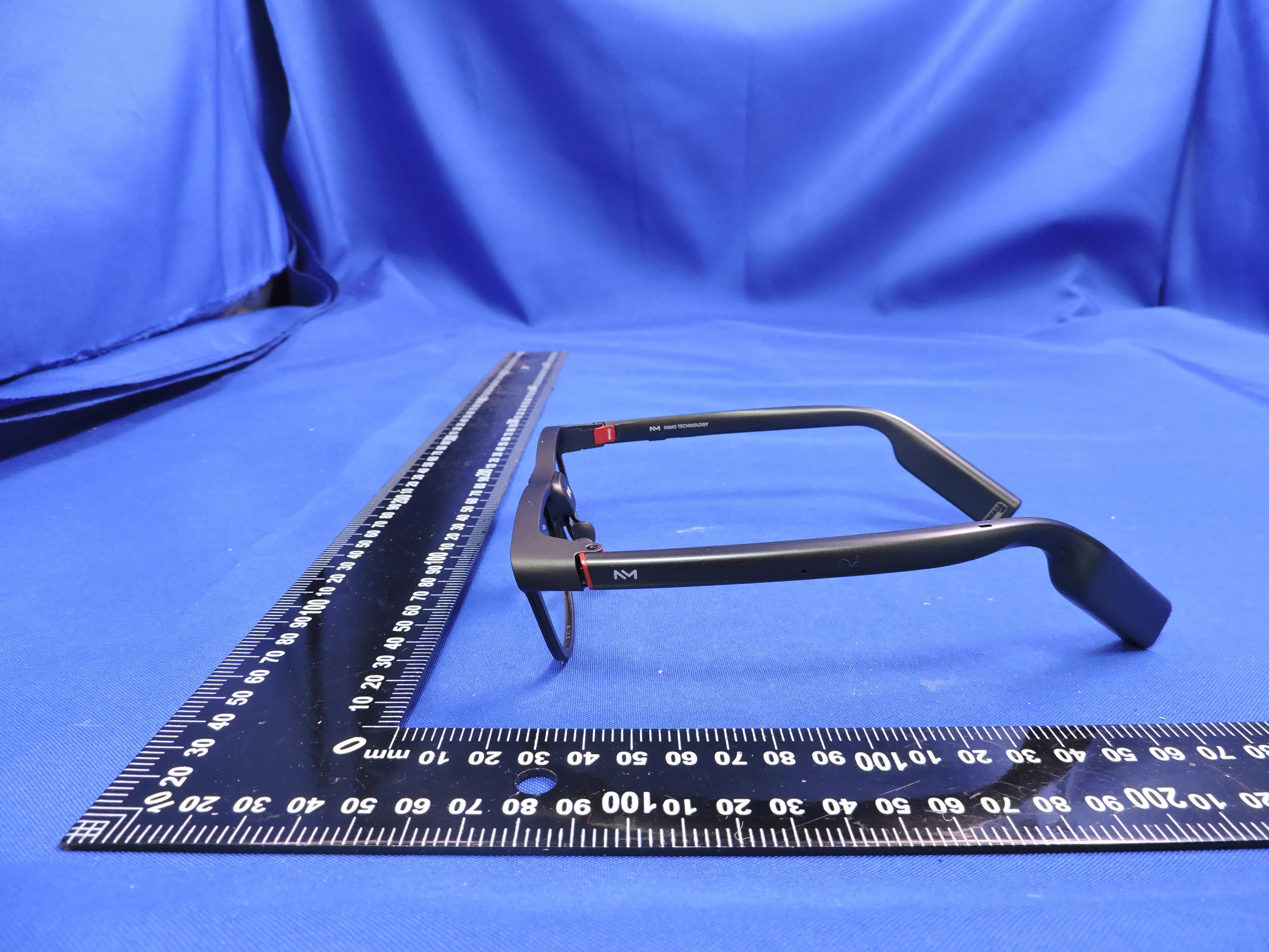
Click to zoom
Application Details
- Equipment Class
- DTS - Digital Transmission System
- Date of Grant
- Jan 30, 2026
- Application Purpose
- Original Equipment
- Equipment Note
- INMO GO3
- Frequency Range
- 2402.00000000 - 2480.00000000
- Country
- China
Documents & Files
Document Text
Text extracted from the exhibit documents filed with the FCC. Open a document above to read the original.
Users Manual
The Esthetic Benchmark in AI Eyewear INMO GO3 Quick Start Installing Myopia Lenses Please first assemble the myopia frame and the myopia lenses. Know Your INMO GO3 Appearance and Buttons 02 Recording Indicator Light Microphone Camera Battery Microphone Speaker Touchpad Microphone Power Button Speaker GO Button Microphone Get Myopia Lenses Prescription Lens Fitting Service Supported Diopter Range for Myopia/Astigmatism If you have myopia or astigmatism, please provide your spectacle prescription (within the last six months) including the sphere, cylinder, axis, and pupillary distance (PD) for both eyes. Take a photo and send it to the official platform. After paying the corresponding fee, we will customize the myopia lenses for you and ship them to you. If you need to fit the lenses yourself, you can contact the official platform customer service to purchase the customized myopia frame and lenses. Getting Started 1. Download the App INMO GO3 requires the INMO App to be used. Please search for "INMO" in the app store, or scan the QR code on the right to download and install the App. INMO GO3 App Download 01 Myopia degree should not exceed 750 degrees, and astigmatism degree should not exceed 450 degrees; Hyperopia (farsightedness) and presbyopia are not supported. 0403 2. Connect the Glasses to the INMO App Press and hold the Power button for 3 seconds to turn on the glasses and keep the screen awake. Launch the INMO App. The App will automatically pop up a connection window. Follow the on-screen prompts to connect. 3. Operation Instructions Power Button GO Button Touchpad Battery Replacement Battery Replacement Charging Charger Product Introduction MagneticMagnetic Instructions for Use Battery Charging Interaction + Power Status Indicator Touchpad Single Tap Confirm Double Tap Back Swipe Switch Long Press Enter Home Screen Power Button Single Tap Screen Off/Screen On Press for 1s Wake up INMO AI, or you can say "Hi, Amu" to wake it up Continue Pressing for 3s Power On/Power Off Continue Pressing for 8s Force Restart GO Button Single Tap Operate according to the on-screen prompts Long Press Shortcut launch function, able to be set Note: The battery is connected magnetically. To replace the battery, gently pull out the battery from the rear of the left temple arm and then insert a new battery. Charging Case Power Indicator Light Charging Port 1. Rotate the charging case cover clockwise 2. Insert the battery to start charging Connect the charging case to a power source to charge the charging case Charging Indicator Light and Status Description Outer Case Power DisplayOuter Case Power Display Indicator Light Indicator Light Power 60-100% Power 30-60% Power 0-30% Solid White Light Solid Orange Light Solid Red Light Indicator Light Color Working Status Less than 30% Greater than 30% but less than 60% Greater than 60% but less than 100% 100% Full Slowly Flashing Red Light Slowly Flashing Orange Light Slowly Flashing White Light Solid White Light Indicator Light Color Working Status *Slowly Flashing Red Light (On for 1s and Off for 2s in cycles) *Slowly Flashing Orange Light (On for 1s and Off for 2s in cycles) *Slowly Flashing White Light (On for 1s and Off for 2s in cycles) 05 Inner Case Charging Status Indicator Package Contents Standard accessories: ① Glasses ②Spare Battery ③Battery Charging Case ④Glasses Cloth ⑤Glasses User Manual (Including Three-guarantee Voucher) 06 No battery Indicator Light With Battery Indicator Light No battery Charging, Power Not Full Power Full Off Slowly Flashing White Light Solid White Light *Slowly Flashing White Light (On for 1s and Off for 0.8s in cycles) Indicator Light Color Working Status Charging Precautions 1. Never use a "one-to-many" charging cable to charge both a smartphone and the charging case simultaneously. 2.Never use a power adapter that has not obtained national CCC certification. Specifications Replaceable Battery Battery: 270mAh Product Weight: 53 grams Optical Composition: Binocular Single Green Micro LED Screen + Diffractive Optical Waveguide Eye Brightness: 1500 nits (adjustable) Model: IMG301 Material:Aluminum Alloy PA Material Processor:Dual-core CPU System: IMOS-3.0 lite Storage: 256MB+64GB Data Transmission: WIFI2.4G+Bluetooth5.4 Interaction Method: Touch Control Physical Buttons Field of View::FOV30° Resolution: 640x480 Physical Buttons: Power Key, GO Key Audio: Microphone ×4, Speaker ×2 Care and Cleaning *Body Maintenance: Please use a soft brush to remove dust from the inner side of the optical waveguide lens or from crevices. *Lens Maintenance: Please use the glasses cloth provided with the product to wipe the optical waveguide lens. Before wiping, ensure that dust particles are removed from the lens surface to avoid scratching the lens (as the lens is fragile, avoid excessive pressure when cleaning). Precautions *Do not excessively bend the temple arms outward, or apply any force that exceeds the mechanical load limit of the product. *Do not twist the frame with both hands, as this may cause the waveguide lens to crack and the frame to deform. *Avoid continuous rotation, fiddling/playing, or throwing (the lens is fragile). *Do not tie the device with the connection cable. *When storing, keep it separate to avoid crushing or collision with sharp objects, which could cause the lens to shatter. Glasses Cloth Spare Battery Glasses Battery Charging Case 0708 Legal Statement Safety Information *Keep the device dry. Do not use the device in dusty, damp, or high-salinity (such as seaside) environments to avoid internal circuit failures. *Do not use this device during thunderstorms, as lightning may cause device failure or electric shock hazards. *Use this device below an altitude of 2000 meters and within a temperature range of 0°C to 40°C. If the ambient temperature is too high or too low, the device may automatically shut down, reduce its service life, and potentially cause other malfunctions. *Do not disassemble or modify the device, in…
Text truncated - open the document above for the full version.
RF Exposure Info
Page: 1/11 SHENZHEN STS TEST SERVICES CO., LTD. 1/F, BUILDING 2, ZHUOKE SCIENCE PARK, 190 CHONGQING ROAD FUYONG, BAO’ AN DISTRICT, SHENZHEN,CHINA MVG COMOSAR DOSIMETRIC E-FIELD PROBE SERIAL NO.: SN 08/21 EPGO352 Calibrated at MVG Z.I. de la pointe du diable Technopôle Brest Iroise – 295 avenue Alexis de Rochon 29280 PLOUZANE - FRANCE Calibration date: 09/15/2025 Accreditations #2-6789 Scope available on www.cofrac.fr The use of the Cofrac brand and the accreditation references is prohibited from any reproduction. Summary: This document presents the method and results from an accredited COMOSAR Dosimetric E-Field Probe calibration performed at MVG, using the CALIPROBE test bench, for use with a MVG COMO SAR system only. The test results covered by accreditation are traceable to the International System of Units (SI). COMOSAR E-Field Probe Calibration Report Ref : ACR.95.19.25.BES.A Docusign Envelope ID: 711C3E09-7054-43A0-BF16-C536091746C4 COMOSAR E-FIELD PROBE CALIBRATION REPORT Ref: ACR.95.19.25.BES.A Page: 2/11 Template_ACR.DDD.N.YY.MVGB.ISSUE_COMOSAR Probe vM This document shall not be reproduced, except in full or in part, without the written approval of MVG. The information contained herein is to be used only for the purpose for which it is submitted and is not to be released in whole or part without written approval of MVG. Name Function Date Signature Prepared by : Pedro Ruiz Measurement Responsible 9/16/2025 Checked & approved by: Jérôme L uc Technical Manager 9/16/2025 Authorized by: Laboratory Director Customer Name Distribution : Shenzhen STS Test Services Co., Ltd. Issue Name Date Modifications A Pedro Ruiz 9/16/2025 Initial release Docusign Envelope ID: 711C3E09-7054-43A0-BF16-C536091746C4 Geraldine Toutain 9/16/2025 COMOSAR E-FIELD PROBE CALIBRATION REPORT Page: 3/11 Template_ACR.DDD.N.YY.MVGB.ISSUE_COMOSAR Probe vM This document shall not be reproduced, except in full or in part, without the written approval of MVG. The information contained herein is to be used only for the purpose for which it is submitted and is not to be released in whole or part without written approval of MVG. TABLE OF CONTENTS 1 Device Under Test ..................................................................................................... 4 2 Product Description ................................................................................................... 4 2.1 General Information _______________________________________________________ 4 3 Measurement Method ................................................................................................ 4 3.1 Sensitivity _______________________________________________________________ 4 3.2 Linearity ________________________________________________________________ 5 3.3 Isotropy _________________________________________________________________ 5 3.4 Boundary Effect __________________________________________________________ 5 3.5 Probe Modulation Response _________________________________________________ 6 4 Measurement Uncertainty .......................................................................................... 6 5 Calibration Results ..................................................................................................... 6 5.1 Calibration in air __________________________________________________________ 6 5.2 Calibration in liquid _______________________________________________________ 7 6 Verification Results ................................................................................................... 8 7 List of Equipment ...................................................................................................... 9 Docusign Envelope ID: 711C3E09-7054-43A0-BF16-C536091746C4 Ref: ACR.95.19.25.BES.A COMOSAR E-FIELD PROBE CALIBRATION REPORT Page: 4/11 Template_ACR.DDD.N.YY.MVGB.ISSUE_COMOSAR Probe vM This document shall not be reproduced, except in full or in part, without the written approval of MVG. The information contained herein is to be used only for the purpose for which it is submitted and is not to be released in whole or part without written approval of MVG. 1 DEVICE UNDER TEST Device Under Test Device Type COMOSAR DOSIMETRIC E FIELD PROBE Manufacturer MVG Model SSE2 Serial Number SN 08/21 EPGO352 Product Condition (new / used) Used Frequency Range of Probe 0.15 GHz-7.5GHz Resistance of Three Dipoles at Connector Dipole 1: R1=0.222 M: Dipole 2: R2=0.198 M: Dipole 3: R3=0.191 M: 2 PRODUCT DESCRIPTION 2.1 GENERAL INFORMATION MVG’s COMOSAR E field Probes are built in accordance to the IEC/IEEE 62209-1528 and FCC KDB865664 D01 standards. Figure 1 – MVG COMOSAR Dosimetric E field Probe Probe Length 330 mm Length of Individual Dipoles 2 mm Maximum external diameter 8 mm Probe Tip External Diameter 2.5 mm Distance between dipoles / probe extremity 1 mm 3 MEASUREMENT METHOD The IEC/IEEE 62209-1528 and FCC KDB865664 D01 standards provide recommended practices for the probe calibrations, including the performance characteristics of interest and methods by which to assess their effect. All calibrations / measurements performed meet the fore-mentioned standards. 3.1 SENSITIVITY The sensitivity factors of the three dipoles were determined using a two step calibration method (air and tissue simulating liquid) using waveguides as outlined in the standards for frequency range 600- 7500MHz and using the calorimeter cell method (transfer method) as outlined in the standards for frequency 150-450 MHz. Docusign Envelope ID: 711C3E09-7054-43A0-BF16-C536091746C4 Ref: ACR.95.19.25.BES.A COMOSAR E-FIELD PROBE CALIBRATION REPORT Page: 5/11 Template_ACR.DDD.N.YY.MVGB.ISSUE_COMOSAR Probe vM This document shall not be reproduced, except in full or in part, without the written approval of MVG. The information contained herein is to be used only for the purpose for which it is submitted and is not to be released in whole or part without written approval of MVG. 3.2 LINEARITY The evaluation of the linearity was done in fr…
Text truncated - open the document above for the full version.
Test Setup Photos
2BP9S-IMG301_SAR Setup photos Back Side(0mm) Left Side(0mm) Right Side(0mm) Top Side(0mm) Bottom Side(0mm)
Test Setup Photos
Page 1 of 2 FCC ID: 2BP9S-IMG301 Setup photo RF Conduction Page 2 of 2 FCC ID: 2BP9S-IMG301 RE (Below 1GHz) RE (Above 1GHz)
Test Report
The test results presented in this report relate only to the object tested. This report shall not be reproduced, except in full, without the written approval of the Shenzhen STS Test Services Co., Ltd. Radio Test Report Report No.:STS2511366W05 Issued for SICHUAN YINGMU TECHNOLOGY CO., LTD No. 3, No. 2, 8th Floor, Building 2, No. 31, Aerospace Road, Chenghua District, Chengdu, Sichuan Province, China. Product Name: INMO GO3 Brand Name: INMO Model Name: IMG301 Series Model(s): N/A FCC ID: 2BP9S-IMG301 Test Standards: FCC Part15.247 Page 2 of 62 Report No.: STS2511366W05 TEST REPORT Applicant’s Name ................. : SICHUAN YINGMU TECHNOLOGY CO., LTD Address .................................. : No. 3, No. 2, 8th Floor, Building 2, No. 31, Aerospace Road, Chenghua District, Chengdu, Sichuan Province, China. Manufacturer's Name ........... : SICHUAN YINGMU TECHNOLOGY CO., LTD Address .................................. : No. 3, No. 2, 8th Floor, Building 2, No. 31, Aerospace Road, Chenghua District, Chengdu, Sichuan Province, China. Product Description Product Name ........................ : INMO GO3 Brand Name ........................... : INMO Model Name ........................... : IMG301 Series Model(s) .................... : N/A Standards ............................. : FCC Part 15.247 Test Procedure........................: ANSI C63.10-2020 This device described above has been tested by STS, the test results show that the equipment under test (EUT) is in compliance with the FCC requirements. And it is applicable only to the tested sample identified in the report. The test results presented in this report relate only to the object tested. This report shall not be reproduced, except in full, without the written approval of the Shenzhen STS Test Services Co., Ltd. Date of Test ............................................ : Date of receipt of test item ...................... : 28 Nov. 2025 Date (s) of performance of tests ............. : 28 Nov. 2025 ~ 17 Dec. 2025 Date of Issue .......................................... : 17 Dec. 2025 Test Result .............................................. : Pass Testing Engineer : (Aaron Bu) Technical Manager : (Skylar Li) Authorized Signatory : (Bovey Yang) Page 3 of 62 Report No.: STS2511366W05 Table of Contents Page 1. SUMMARY OF TEST RESULTS 6 1.1 TEST FACTORY 7 1.2 MEASUREMENT UNCERTAINTY 7 2. GENERAL INFORMATION 8 2.1 GENERAL DESCRIPTION OF THE EUT 8 2.2 DESCRIPTION OF THE TEST MODES 10 2.3 TEST SOFTWARE AND POWER LEVEL 10 2.4 BLOCK DIAGRAM SHOWING THE CONFIGURATION OF SYSTEM TESTED 11 RF CONDUCTED TEST 11 2.6 EQUIPMENTS LIST FOR ALL TEST ITEMS 12 3. EMC EMISSION TEST 13 3.1 CONDUCTED EMISSION MEASUREMENT 13 3.2 RADIATED EMISSION MEASUREMENT 15 4. CONDUCTED SPURIOUS & BAND EDGE EMISSION 27 4.1 LIMIT 27 4.2 TEST PROCEDURE 27 4.3 DEVIATION FROM STANDARD 27 4.4 TEST SETUP 27 4.5 EUT OPERATION CONDITIONS 27 4.6 TEST RESULTS 27 5. POWER SPECTRAL DENSITY TEST 28 5.1 LIMIT 28 5.2 TEST PROCEDURE 28 5.3 DEVIATION FROM STANDARD 28 5.4 TEST SETUP 28 5.5 EUT OPERATION CONDITIONS 28 5.6 TEST RESULTS 28 6. BANDWIDTH TEST 29 6.1 LIMIT 29 6.2 TEST PROCEDURE 29 6.3 DEVIATION FROM STANDARD 29 6.4 TEST SETUP 29 6.5 EUT OPERATION CONDITIONS 29 Page 4 of 62 Report No.: STS2511366W05 Table of Contents Page 6.6 TEST RESULTS 29 7. PEAK OUTPUT POWER TEST 30 7.1 LIMIT 30 7.2 TEST PROCEDURE 30 7.3 DEVIATION FROM STANDARD 30 7.4 TEST SETUP 30 7.5 EUT OPERATION CONDITIONS 30 7.6 TEST RESULTS 30 8. ANTENNA REQUIREMENT 31 8.1 STANDARD REQUIREMENT 31 8.2 EUT ANTENNA 31 APPENDIX 1-TEST DATA 32 MAXIMUM PEAK CONDUCTED OUTPUT POWER 32 -6DB BANDWIDTH 33 MAXIMUM POWER SPECTRAL DENSITY LEVEL 39 BAND EDGE 45 CONDUCTED RF SPURIOUS EMISSION 52 APPENDIX 2-PHOTOS OF TEST SETUP 62 Page 5 of 62 Report No.: STS2511366W05 Revision History Rev. Issue Date Report No. Effect Page Contents 00 17 Dec. 2025 STS2511366W05 ALL Initial Issue Page 6 of 62 Report No.: STS2511366W05 1. SUMMARY OF TEST RESULTS Test procedures according to the technical standards: KDB 558074 D01 15.247 Meas Guidance v05r02. FCC Part 15.247,Subpart C Standard Section Test Item Judgment Remark 15.207 Conducted Emission N/A -- 15.247 (a)(2) 6dB Bandwidth PASS -- 15.247 (b)(3) Output Power PASS -- 15.209 Radiated Spurious Emission PASS -- 15.247 (d) Conducted Spurious & Band Edge Emission PASS -- 15.247 (e) Power Spectral Density PASS -- 15.205 Restricted Band Edge Emission PASS -- Part 15.247(d)/ part 15.209(a) Band Edge Emission PASS -- 15.203 Antenna Requirement PASS -- NOTE: (1) ‘N/A’ denotes test is not applicable in this Test Report. (2) All tests are according to ANSI C63.10-2020. Page 7 of 62 Report No.: STS2511366W05 1.1 TEST FACTORY SHENZHEN STS TEST SERVICES CO., LTD Add. : 101, Building B, Zhuoke Science Park, No.190 Chongqing Road, ZhanChengShequ, Fuhai Sub-District, Bao’an District, Shenzhen, Guang Dong, China FCC test Firm Registration Number: 625569 IC test Firm Registration Number: 12108A A2LA Certificate No.: 4338.01 1.2 MEASUREMENT UNCERTAINTY The reported uncertainty of measurement y ±U, where expended uncertainty U is based on a standard uncertainty multiplied by a coverage factor of k=2, providing a level of confidence of approximately 95 %. No. Item Uncertainty 1 RF output power, conducted ±0.751dB 2 Unwanted Emissions, conducted ±2.888dB 3 All emissions, radiated 9K-30MHz ±2.48dB 4 All emissions, radiated 30M-1GHz ±2.52dB 5 All emissions, radiated 1G-18GHz ±3.48dB 6 All emissions, radiated>18GHz ±4.18dB 7 Conducted Emission (9KHz-150KHz) ±2.48dB 8 Conducted Emission (150KHz-30MHz) ±2.52dB 9 Occupied Channel Bandwidth ±3.6% 10 Power Spectral Density, conducted ±1.214dB 11 Duty Cycle ±3.2% Page 8 of 62 Report No.: STS2511366W05 2. GENERAL INFORMATION 2.1 GENERAL DESCRIPTION OF THE EUT Product Name INMO GO3 Brand Name INMO Model Name IMG301 Series Model(s) N/A Model Difference N/A Product Description The EUT is a INMO GO3 Operation Frequency: 802.11b/g/n 20: 2412~2462 MHz Modulation Type: 802.11b(DSSS):…
Text truncated - open the document above for the full version.
Test Report
The test results presented in this report relate only to the object tested. This report shall not be reproduced, except in full, without the written approval of the Shenzhen STS Test Services Co., Ltd. Radio Test Report Report No.:STS2511366W04 Issued for SICHUAN YINGMU TECHNOLOGY CO., LTD No. 3, No. 2, 8th Floor, Building 2, No. 31, Aerospace Road, Chenghua District, Chengdu, Sichuan Province, China. Product Name: INMO GO3 Brand Name: INMO Model Name: IMG301 Series Model(s): N/A FCC ID: 2BP9S-IMG301 Test Standards: FCC Part15.247 Page 2 of 48 Report No.: STS2511366W04 TEST REPORT Applicant’s Name ..................: SICHUAN YINGMU TECHNOLOGY CO., LTD Address ..................................: No. 3, No. 2, 8th Floor, Building 2, No. 31, Aerospace Road, Chenghua District, Chengdu, Sichuan Province, China. Manufacturer's Name ...........: SICHUAN YINGMU TECHNOLOGY CO., LTD Address ..................................: No. 3, No. 2, 8th Floor, Building 2, No. 31, Aerospace Road, Chenghua District, Chengdu, Sichuan Province, China. Product Description Product Name .........................: INMO GO3 Brand Name ...........................: INMO Model Name ...........................: IMG301 Series Model(s) .....................: N/A Standards ..............................: FCC Part15.247 Test Procedure .......................: ANSI C63.10-2020 This device described above has been tested by STS, the test results show that the equipment under test (EUT) is in compliance with the FCC requirements. And it is applicable only to the tested sample identified in the report. The test results presented in this report relate only to the object tested. This report shall not be reproduced, except in full, without the written approval of the Shenzhen STS Test Services Co., Ltd. Date of Test ............................................ : Date of receipt of test item ...................... : 28 Nov. 2025 Date (s) of performance of tests ............. : 28 Nov. 2025 ~ 17 Dec. 2025 Date of Issue ........................................... : 17 Dec. 2025 Test Result ............................................... : Pass Testing Engineer : (Aaron Bu) Technical Manager : (Skylar Li) Authorized Signatory : (Bovey Yang) Page 3 of 48 Report No.: STS2511366W04 Table of Contents Page 1. SUMMARY OF TEST RESULTS 6 1.1 TEST FACTORY 7 1.2 MEASUREMENT UNCERTAINTY 7 2. GENERAL INFORMATION 8 2.1 GENERAL DESCRIPTION OF THE EUT 8 2.2 DESCRIPTION OF THE TEST MODES 9 2.3 TEST SOFTWARE AND POWER LEVEL 9 2.4 BLOCK DIAGRAM SHOWING THE CONFIGURATION OF SYSTEM TESTED 10 2.5 DESCRIPTION OF NECESSARY ACCESSORIES AND SUPPORT UNITS 10 2.6 EQUIPMENTS LIST 11 3. EMC EMISSION TEST 12 3.1 CONDUCTED EMISSION MEASUREMENT 12 3.2 TEST PROCEDURE 13 3.3 TEST SETUP 13 3.4 EUT OPERATING CONDITIONS 13 3.5 TEST RESULTS 13 4. RADIATED EMISSION MEASUREMENT 14 4.1 RADIATED EMISSION LIMITS 14 4.2 TEST PROCEDURE 16 4.3 TEST SETUP 17 4.4 EUT OPERATING CONDITIONS 17 4.5 FIELD STRENGTH CALCULATION 18 4.6 TEST RESULTS 19 5. CONDUCTED SPURIOUS & BAND EDGE EMISSION 26 5.1 LIMIT 26 5.2 TEST PROCEDURE 26 5.3 TEST SETUP 26 5.4 EUT OPERATION CONDITIONS 26 5.5 TEST RESULTS 26 6. POWER SPECTRAL DENSITY TEST 27 6.1 LIMIT 27 6.2 TEST PROCEDURE 27 6.3 TEST SETUP 27 Page 4 of 48 Report No.: STS2511366W04 Table of Contents Page 6.4 EUT OPERATION CONDITIONS 27 6.5 TEST RESULTS 27 7. BANDWIDTH TEST 28 7.1 LIMIT 28 7.2 TEST PROCEDURE 28 7.3 TEST SETUP 28 7.4 EUT OPERATION CONDITIONS 28 7.5 TEST RESULTS 28 8. PEAK OUTPUT POWER TEST 29 8.1 LIMIT 29 8.2 TEST PROCEDURE 29 8.3 TEST SETUP 30 8.4 EUT OPERATION CONDITIONS 30 8.5 TEST RESULTS 30 9. ANTENNA REQUIREMENT 31 9.1 STANDARD REQUIREMENT 31 9.2 EUT ANTENNA 31 APPENDIX 1-TEST DATA 32 MAXIMUM PEAK CONDUCTED OUTPUT POWER 32 -6DB BANDWIDTH 35 MAXIMUM POWER SPECTRAL DENSITY LEVEL 38 BAND EDGE 41 CONDUCTED RF SPURIOUS EMISSION 44 APPENDIX 2- EUT TEST PHOTO 48 Page 5 of 48 Report No.: STS2511366W04 Revision History Rev. Issue Date Report No. Effect Page Contents 00 17 Dec. 2025 STS2511366W04 ALL Initial Issue Page 6 of 48 Report No.: STS2511366W04 1. SUMMARY OF TEST RESULTS Test procedures according to the technical standards: KDB 558074 D01 15.247 Meas Guidance v05r02. FCC Part 15.247,Subpart C Standard Section Test Item Judgment Remark 15.207 Conducted Emission N/A -- 15.247 (a)(2) 6dB Bandwidth PASS -- 15.247 (b)(3) Output Power PASS -- 15.209 Radiated Spurious Emission PASS -- 15.247 (d) Conducted Spurious & Band Edge Emission PASS -- 15.247 (e) Power Spectral Density PASS -- 15.205 Restricted bands of operation PASS -- Part 15.247(d)/ Part 15.209(a) Band Edge Emission PASS -- 15.203 Antenna Requirement PASS -- Note: (1) ‘N/A’ denotes test is not applicable in this Test Report. (2) All tests are according to ANSI C63.10-2020. Page 7 of 48 Report No.: STS2511366W04 1.1 TEST FACTORY SHENZHEN STS TEST SERVICES CO., LTD Add. : 101, Building B, Zhuoke Science Park, No.190 Chongqing Road, ZhanChengShequ, Fuhai Sub-District, Bao’an District, Shenzhen, Guang Dong, China FCC test Firm Registration Number: 625569 IC test Firm Registration Number: 12108A A2LA Certificate No.: 4338.01 1.2 MEASUREMENT UNCERTAINTY The reported uncertainty of measurement y ± U, where expended uncertainty U is based on a standard uncertainty multiplied by a coverage factor of k=2, providing a level of confidence of approximately 95 %. No. Item Uncertainty 1 RF output power, conducted ±0.751dB 2 Unwanted Emissions, conducted ±2.888dB 3 All emissions, radiated 9K-30MHz ±2.48dB 4 All emissions, radiated 30M-1GHz ±2.52dB 5 All emissions, radiated 1G-18GHz ±3.48dB 6 All emissions, radiated>18GHz ±4.18dB 7 Conducted Emission (9KHz-150KHz) ±2.48dB 8 Conducted Emission (150KHz-30MHz) ±2.52dB 9 Occupied Channel Bandwidth ±3.6% 10 Power Spectral Density, conducted ±1.214dB 11 Duty Cycle ±3.2% Page 8 of 48 Report No.: STS2511366W04 2. GENERAL INFORMATION 2.1 GENERAL DESCRIPTION OF THE EUT Product Name INMO GO3 Brand Name INMO Model Name IMG301 Series Model(s) N/A Model Di…
Text truncated - open the document above for the full version.
Test Report
The test results presented in this report relate only to the object tested. This report shall not be reproduced, except in full, without the written approval of the Shenzhen STS Test Services Co., Ltd. Radio Test Report Report No.:STS2511366W03 Issued for SICHUAN YINGMU TECHNOLOGY CO., LTD No. 3, No. 2, 8th Floor, Building 2, No. 31, Aerospace Road, Chenghua District, Chengdu, Sichuan Province, China. Product Name: INMO GO3 Brand Name: INMO Model Name: IMG301 Series Model(s): N/A FCC ID: 2BP9S-IMG301 Test Standards: FCC Part15.247 Page 2 of 48 Report No.: STS2511366W03 TEST REPORT Applicant’s Name ..................: SICHUAN YINGMU TECHNOLOGY CO., LTD Address ..................................: No. 3, No. 2, 8th Floor, Building 2, No. 31, Aerospace Road, Chenghua District, Chengdu, Sichuan Province, China. Manufacturer's Name ...........: SICHUAN YINGMU TECHNOLOGY CO., LTD Address ..................................: No. 3, No. 2, 8th Floor, Building 2, No. 31, Aerospace Road, Chenghua District, Chengdu, Sichuan Province, China. Product Description Product Name .........................: INMO GO3 Brand Name ...........................: INMO Model Name ...........................: IMG301 Series Model(s) .....................: N/A Standards ..............................: FCC Part15.247 Test Procedure .......................: ANSI C63.10-2020 This device described above has been tested by STS, the test results show that the equipment under test (EUT) is in compliance with the FCC requirements. And it is applicable only to the tested sample identified in the report. The test results presented in this report relate only to the object tested. This report shall not be reproduced, except in full, without the written approval of the Shenzhen STS Test Services Co., Ltd. Date of Test ............................................ : Date of receipt of test item ...................... : 28 Nov. 2025 Date (s) of performance of tests ............. : 28 Nov. 2025 ~ 17 Dec. 2025 Date of Issue ........................................... : 17 Dec. 2025 Test Result ............................................... : Pass Testing Engineer : (Aaron Bu) Technical Manager : (Skylar Li) Authorized Signatory : (Bovey Yang) Page 3 of 48 Report No.: STS2511366W03 Table of Contents Page 1. SUMMARY OF TEST RESULTS 6 1.1 TEST FACTORY 7 1.2 MEASUREMENT UNCERTAINTY 7 2. GENERAL INFORMATION 8 2.1 GENERAL DESCRIPTION OF THE EUT 8 2.2 DESCRIPTION OF THE TEST MODES 9 2.3 TEST SOFTWARE AND POWER LEVEL 9 2.4 BLOCK DIAGRAM SHOWING THE CONFIGURATION OF SYSTEM TESTED 10 2.5 DESCRIPTION OF NECESSARY ACCESSORIES AND SUPPORT UNITS 10 2.6 EQUIPMENTS LIST 11 3. EMC EMISSION TEST 12 3.1 CONDUCTED EMISSION MEASUREMENT 12 3.2 TEST PROCEDURE 13 3.3 TEST SETUP 13 3.4 EUT OPERATING CONDITIONS 13 3.5 TEST RESULTS 13 4. RADIATED EMISSION MEASUREMENT 14 4.1 RADIATED EMISSION LIMITS 14 4.2 TEST PROCEDURE 16 4.3 TEST SETUP 17 4.4 EUT OPERATING CONDITIONS 17 4.5 FIELD STRENGTH CALCULATION 18 4.6 TEST RESULTS 19 5. CONDUCTED SPURIOUS & BAND EDGE EMISSION 26 5.1 LIMIT 26 5.2 TEST PROCEDURE 26 5.3 TEST SETUP 26 5.4 EUT OPERATION CONDITIONS 26 5.5 TEST RESULTS 26 6. POWER SPECTRAL DENSITY TEST 27 6.1 LIMIT 27 6.2 TEST PROCEDURE 27 6.3 TEST SETUP 27 Page 4 of 48 Report No.: STS2511366W03 Table of Contents Page 6.4 EUT OPERATION CONDITIONS 27 6.5 TEST RESULTS 27 7. BANDWIDTH TEST 28 7.1 LIMIT 28 7.2 TEST PROCEDURE 28 7.3 TEST SETUP 28 7.4 EUT OPERATION CONDITIONS 28 7.5 TEST RESULTS 28 8. PEAK OUTPUT POWER TEST 29 8.1 LIMIT 29 8.2 TEST PROCEDURE 29 8.3 TEST SETUP 30 8.4 EUT OPERATION CONDITIONS 30 8.5 TEST RESULTS 30 9. ANTENNA REQUIREMENT 31 9.1 STANDARD REQUIREMENT 31 9.2 EUT ANTENNA 31 APPENDIX 1-TEST DATA 32 MAXIMUM PEAK CONDUCTED OUTPUT POWER 32 -6DB BANDWIDTH 35 MAXIMUM POWER SPECTRAL DENSITY LEVEL 38 BAND EDGE 41 CONDUCTED RF SPURIOUS EMISSION 44 APPENDIX 2- EUT TEST PHOTO 48 Page 5 of 48 Report No.: STS2511366W03 Revision History Rev. Issue Date Report No. Effect Page Contents 00 17 Dec. 2025 STS2511366W03 ALL Initial Issue Page 6 of 48 Report No.: STS2511366W03 1. SUMMARY OF TEST RESULTS Test procedures according to the technical standards: KDB 558074 D01 15.247 Meas Guidance v05r02. FCC Part 15.247,Subpart C Standard Section Test Item Judgment Remark 15.207 Conducted Emission N/A -- 15.247 (a)(2) 6dB Bandwidth PASS -- 15.247 (b)(3) Output Power PASS -- 15.209 Radiated Spurious Emission PASS -- 15.247 (d) Conducted Spurious & Band Edge Emission PASS -- 15.247 (e) Power Spectral Density PASS -- 15.205 Restricted bands of operation PASS -- Part 15.247(d)/ Part 15.209(a) Band Edge Emission PASS -- 15.203 Antenna Requirement PASS -- Note: (1) ‘N/A’ denotes test is not applicable in this Test Report. (2) All tests are according to ANSI C63.10-2020. Page 7 of 48 Report No.: STS2511366W03 1.1 TEST FACTORY SHENZHEN STS TEST SERVICES CO., LTD Add. : 101, Building B, Zhuoke Science Park, No.190 Chongqing Road, ZhanChengShequ, Fuhai Sub-District, Bao’an District, Shenzhen, Guang Dong, China FCC test Firm Registration Number: 625569 IC test Firm Registration Number: 12108A A2LA Certificate No.: 4338.01 1.2 MEASUREMENT UNCERTAINTY The reported uncertainty of measurement y ± U, where expended uncertainty U is based on a standard uncertainty multiplied by a coverage factor of k=2, providing a level of confidence of approximately 95 %. No. Item Uncertainty 1 RF output power, conducted ±0.751dB 2 Unwanted Emissions, conducted ±2.888dB 3 All emissions, radiated 9K-30MHz ±2.48dB 4 All emissions, radiated 30M-1GHz ±2.52dB 5 All emissions, radiated 1G-18GHz ±3.48dB 6 All emissions, radiated>18GHz ±4.18dB 7 Conducted Emission (9KHz-150KHz) ±2.48dB 8 Conducted Emission (150KHz-30MHz) ±2.52dB 9 Occupied Channel Bandwidth ±3.6% 10 Power Spectral …
Text truncated - open the document above for the full version.
Contact Information
Applicant
yongyi Liang(Quality Director)
[email protected]Fax: 13632342392
Technical Contact
AOGES CO., LIMITEDXIAOYAN LAI
1624 Market St., Ste 226, #30327 · Denver, Colorado, 80202 · United States
Test Firm
SHENZHEN STS TEST SERVICES CO.,LTD.Bovey Yang
Technical Specifications
| # | Rule Parts | Frequency Range | Power Output |
|---|---|---|---|
| 1 | 15C | 2.40 GHz - 2.48 GHz | 11.10 mW |
| 2 | 15C | 2.41 GHz - 2.46 GHz | 134.00 mW |