2BQHE-R80Thermal Printer
Guangdong Gilong Technology Co., Ltd.
Click to zoom
Application Details
- Equipment Class
- DTS - Digital Transmission System
- Date of Grant
- Sep 12, 2025
- Application Purpose
- Original Equipment
- Equipment Note
- Thermal Printer
- Frequency Range
- 2402.00000000 - 2480.00000000
- Country
- China
Documents & Files
Document Text
Text extracted from the exhibit documents filed with the FCC. Open a document above to read the original.
Users Manual
Thermal Receipt Printer User Manual (Note: Interfaces shown in the manual's model images are for reference only, please refer to the actual product for accuracy.) Product Packing List: Printer connection Printer connection The 80 series printer uses 80mm thermal paper rolls with an easy paper loading structure. Follow these steps to install the thermal paper: User Manual Printer Main Unit Data Connection Cable (excluding Ethernet, based on interface configuration) Power Adapter (including power cable) Test Paper A. Connect the adapter cable to the printer's power interface. B. Connect the interface cable to the rear port of the printer. C. Connect the cash drawer cable to the cash drawer interface at the back of the printer. ① Search by Wechat for “Guangdong Gilong Technology Co.” ② For downloading related materials, please visit the official Gilong website: www.Jprinter.com. Gilong homepage >> Service & Support >>Driver Download >> 80 Series driver >> click on Download to save. Gilong homepage >> Product Center >> Choose the 80 Series product, click on the product to enter the model page >> Click on Driver Download >> save the file. Method(2) Method(3) 1 piece 1 unit 1 cable 1 set 1 roll ( 1 )Open the printer cover. ( 2 )Place the thermal paper roll into the paper compartment as shown in the diagram. ( 3 )Pull a small portion of the paper out of the compartment, then close the cover. ( 4 )Tear off the excess paper using the machine's cutter. Install the paper roll Manufacturer: Guangdong Gilong Technology Co., Ltd. htpp://www.jprinter.com Please keep use manual for reference Certificate Inspector: 01 Q.C. PASSED Warning: This manual may not be altered without consent. We reserve the right to modify the product's technical specifica- tions, components, software, and hardware. For further information regarding the product, users are encouraged to contact their dealer. No part of this manual may be reproduced or transmitted in any form or by any means without permission. Warning Operating this equipment in a residential environment- may cause radio interference. Method: Search for Guangdong Gilong Technology Co., Ltd. on Wechat or scan the QR code below to follow the official account. Guangdong Gilong Technology Co., Ltd. Wechat Official Account Driver download methods are as follows: Method(1) Power AdapterWrong Method Power interface Power Adapter LAN USB Cash box mouth Button Names, Indicator Lights, and Functions Precautions (1) Feed Button( ) Printer Function OverviewSelf-diagnostic Test 1. The printer should be installed on a stable surface to avoid vibrations and impacts. 2. Avoid using and storing the printer in high temperatures, high humidity, or heavily polluted environments. 3. Connect the printer's power adapter to a properly grounded socket. Avoid sharing the socket with large motors or devices that may cause power fluctuations. 4. Prevent water or conductive materials (such as metal) from entering the interior of the printer. If this occurs, immediately turn off the power. 5. Do not operate the printer without paper, as it can damage the print roller and thermal print head. 6. If the printer will be unused for a long period, disconnect the power adpter. 7. Do not disassemble or modify the printer yourself. 8. Only use the provided power adapter. 9. For best results and printer longevity, use high-quality printing paper. 10. Ensure the printer power is off when plugging or unplugging cables. 11. The adapter's power plug serves as a disconnect device and should be easily accessible near the equipment. 12. This product is only suitable for use below 5000 meters altitude and under tropical climate conditions. During the warranty period, the following situations will void the warranty service: Printer Warranty Card 1. Damage or malfunction due to improper use by the user. 2. Damage or malfunction caused by unauthorized disassembly or repair by the user or unauthorized personnel. 3. Damage or malfunction caused by force majeure. 4. Lack of warranty or purchase documents, discrepancies between the purchase documents and the product, or alterations to them. Dear Customer: Thank you for choosing our receipt printer product. We provide efficient and high-quality warranty services to protect your interests. With your warranty card and purchase receipt, you can enjoy a one-year warranty from the date of purchase. During this period, any damage to parts or machine malfunction due to quality issues will be repaired or replaced free of charge. Damage or malfunctions occurring after the warranty period or due to the above conditions will require appropriate fees for replacement or repair. Printer Cleaning When the printer exhibits the following issues, clean the print head promptly: 1. Unclear printing. 2. Vertical lines on printed pages are unclear. 3. Excessive noise during paper feeding. Print head cleaning steps: 1. Turn off the printer, open the top cover, and remove any paper if present. 2. If the printer has just been used, allow the print head to cool completely. 3. Use a soft cloth dipped in anhydrous ethanol (make sure it is wrung dry) to wipe away dust and stains from the surface of the print head. 4. Wait for the anhydrous ethanol to fully evaporate before closing the cover and attempting to print again. 1. It is essential to ensure that the power is turned off during routine maintenance of the printer. 2. Do not touch the surface of the print head with hands or metal objects, and avoid scratching the print head, print roller, and sensor surfaces with tools like tweezers. 3. Do not use organic solvents such as gasoline or acetone. 4. Wait for anhydrous ethanol to completely evaporate before turning on the power to resume printing. Self-check method: Plug in the printer. While it is turned off, hold down the paper feed button for two seconds and then press the power button simultaneously. This will print out the current parameter settings of the printer. Press this button once to…
Text truncated - open the document above for the full version.
RF Exposure Info
FCC ID: 2BQHE-R80 Prediction of MPE at a given distance 1. Limits The criteria listed in the following table shall be used to evaluate the environment impact of human exposure to radio frequency (RF) radiation as specified in 1.1307(b) 2. Test Procedure Equation from page 18 of OET Bulletin 65, Edition 97-01 Where: S = power density P = power input to the antenna G = numeric gain of the antenna in the direction of interest relative to an isotropic radiator R = distance to the center of radiation of the antenna FCC ID: 2BQHE-R80 3. Result Mode Frequency (MHz) Prediction distance (cm) Rated Peak RF power output MPE (mW/cm 2 ) Limit (mW/cm 2 ) SAR Test Exclusion dBm mW 2.4G WIFI 2462 20 15.559 35.9667 0.01155 1 Yes BLE 1M 2440 20 -3.704 0.4262 0.00007 1 Yes 5G WIFI 5500 20 10.219 10.5172 0.00305 1 Yes Use distance is 20cm, Maximum Simultaneous transmission MPE Ratios for BLE+WIFI: Max MPE ratio BLE /Limit Max MPE ratio WIFI /Limit ∑MPE ratios Limit Result 0.00007 0.01155 0.01162 1 PASS 2.4G WiFi Antenna Gain: 2.08dBi, 1.61(numeric) BT Antenna Gain: -0.58dBi, 0.87(numeric) 5G WiFi Antenna Gain: 1.63dBi, 1.46(numeric) Then SAR evaluation is not required.
Test Setup Photos
FCC ID: 2BQHE-R80 1.1. Photos of Radiated emission FCC ID: 2BQHE-R80 1.2. Photos of Conducted Emission test
Test Report
文件编号: Specification For Approval 客户名称: Customer: 深圳巨隆电子有限公司 Guangdong Gilong Technology Co., Ltd. 供应商名称: Customer: 深圳市畅威达科技有限公司 Shenzhen Changweida Technology Co., Ltd 地址: Address: 深圳市龙华区大浪街道浪口社区华盛路175号3栋302(臻嘉工业园) 302, Building 3, No. 175 Huasheng Road, Langkou Community, Dalang Street, Longhua District, Shenzhen (Zhenjia Industrial Park) 客户料号: 供应商料号: 产品描述: 0.81黑色3代端子 L=100MM FPC:HT-WIFI-003 配用机型: 供应商承认(盖章): 客户承认(盖章): 0.81黑色3代端子 L=100MM FPC:HT-WIFI-003 制作:曾涛 结构:张登刚 审核: 日期:2025.08.13 Contents Description Page 1、封面 Cover ----------------------------------------------------- 1 2、目录 Contents ------------------------------------------------- 2 3、规格表 Specifications sheets --------------------------- 3 4、成品图 End product chart ------------------------------- 4 5、成品图 End product chart ----------------------------- 5-6 产品主要技术参数 Main technical specifications 主要技术指标 Main technical specifications 频率范围 (MHZ) 2400-2500 Frequency Range (MHZ) 2400-2500 中心频率 特性阻抗 (Ω) 50 Impedance(Ω) 50 增益(dBi) 2.08 Gain(dBi) 2.08 输出电压 驻波比 ≤2.0 VSWR ≤2.0 极化方式 线极化 Polarization Linear 方向性 全向性 Radiation Omni-directional 物理性能 Physical Properties 天线本体 材料 FPC Antenna Base FPC 工作温度 -20°C~+80°C Operating Temp -20°C~+80°C 保存温度 -20°C~+50°C Storage Temp -20°C~+50°C 产品主要技术参数 Main technical specifications 主要技术指标 Main technical specifications 频率范围 (MHZ) 5150-5850 Frequency Range (MHZ) 5150-5850 中心频率 特性阻抗 (Ω) 50 Impedance(Ω) 50 增益(dBi) 1.63 Gain(dBi) 1.63 输出电压 驻波比 ≤2.0 VSWR ≤2.0 极化方式 线极化 Polarization Linear 方向性 全向性 Radiation Omni-directional 物理性能 Physical Properties 天线本体 材料 FPC Antenna Base FPC 工作温度 -20°C~+80°C Operating Temp -20°C~+80°C 保存温度 -20°C~+50°C Storage Temp -20°C~+50°C 5、成品图【End product chart】: 深圳市畅威达科技有限公司 张登刚 曾涛 6、测试报告【Testing report】 6.1 网络分析仪测试报告 频率(MHz) Return Loss(dB) VSWR 2400 -12.12 1.65 2500 -15.52 1.40 5150 -17.71 1.30 5350 -22.99 1.15 5750 -22.92 1.15 5850 -15.52 1.13 6.2 :暗室 2D、3D Radiation Pattern,效率及增益 Frequency / MHz Gain/ dBi Efficiency / % 2400 2.03 48.02 2450 2.08 49.18 2500 2.05 48.03 5150 1.53 43.7 5350 1.62 42.04 5750 0.83 43.8 5850 1.06 42.2
Test Report
ANTENNA SPECIFICATION Summary ITEMANT SPEC Model Name Bluetooth ANT Center Frequency HorizontalVertical 2400MHz2450MHz2500MHz2400MHz2450MHz2500MHz -1.73-0.84-0.58-6.15-3.7-2.32 MAX. Gain-0.58dBi PolarizationHorizontal and Vertical Azimuth Beam Pattern Omni-directional Impedance50 Ohm Antenna Length41.1mm Manufacture Antenna Photo & Length (mm) Manufacturer: Guangdong Gilong Technology Co., Ltd. Address:4-5F, Building A11, Haidi Fashion Meidu Industrial Park, Haifeng County, Shanwei, Guangdong, China. Horizontal:2400MHz2450MHz2500MHz Max:0Min:-40Scale:5/div FrequencyGain(dB) (MHz)MaxMinAvg 2400-1.73178-30.0815-8.48713 2450-0.845801-38.5605-7.88012 2500-0.585586-24.0318-6.79139 Vertical:2400MHz2450MHz2500MHz Max:0Min:-30Scale:5/div FrequencyGain(dB) (MHz)MaxMinAvg 2400-6.153-24.142-13.0295 2450-3.7054-26.5836-10.67 2500-2.32122-30.4301-9.70536
Test Report
Page 87 of 101 Report No.: A2504097-C01-R01 Page 88 of 101 Report No.: A2504097-C01-R01 Page 89 of 101 Report No.: A2504097-C01-R01 Page 90 of 101 Report No.: A2504097-C01-R01 2.4G WIFI/5G WIF ANT Page 91 of 101 Report No.: A2504097-C01-R01 Page 92 of 101 Report No.: A2504097-C01-R01 Page 93 of 101 Report No.: A2504097-C01-R01 Page 94 of 101 Report No.: A2504097-C01-R01 BT ANT Page 95 of 101 Report No.: A2504097-C01-R01 Page 96 of 101 Report No.: A2504097-C01-R01 Page 97 of 101 Report No.: A2504097-C01-R01 Page 98 of 101 Report No.: A2504097-C01-R01 Page 99 of 101 Report No.: A2504097-C01-R01 Page 100 of 101 Report No.: A2504097-C01-R01 Page 101 of 101 Report No.: A2504097-C01-R01 15. MODEL LIST JP-R80A JP-R80B JP-R80C JP-R80D JP-R80E JP-R80F JP-R80G JP-R810 JP-R820 JP-R830 JP-R840 JP-R850 JP-R860 GL-R80A GL-R80B GL-R80C GL-R80D GL-R80E GL-R80F GL-R80G GL-R810 GL-R820 GL-R830 GL-R840 GL-R850 GL-R860 JP-B20 JP-B30 JP-B410 JP-B411 JP-B311 JP-M3 JP-M32 JP-M33 JP-M4 JP-M42 JP-M43 -------END OF REPORT-------
Test Report
Page 53 of 101 Report No.: A2504097-C01-R01 -6dB Bandwidth NVNT n20 2462MHz Ant1 -6dB Bandwidth NVNT n40 2422MHz Ant1 Page 54 of 101 Report No.: A2504097-C01-R01 -6dB Bandwidth NVNT n40 2437MHz Ant1 -6dB Bandwidth NVNT n40 2452MHz Ant1 Page 55 of 101 Report No.: A2504097-C01-R01 Occupied Channel Bandwidth Condition Mode Frequency (MHz) Antenna 99% ObW (MHz) NVNT b 2412 Ant1 14.625 NVNT b 2437 Ant1 14.625 NVNT b 2462 Ant1 14.625 NVNT g 2412 Ant1 16.484 NVNT g 2437 Ant1 16.513 NVNT g 2462 Ant1 16.573 NVNT n20 2412 Ant1 17.712 NVNT n20 2437 Ant1 17.682 NVNT n20 2462 Ant1 17.622 NVNT n40 2422 Ant1 35.784 NVNT n40 2437 Ant1 35.784 NVNT n40 2452 Ant1 35.844 OBW NVNT b 2412MHz Ant1 Page 56 of 101 Report No.: A2504097-C01-R01 OBW NVNT b 2437MHz Ant1 OBW NVNT b 2462MHz Ant1 Page 57 of 101 Report No.: A2504097-C01-R01 OBW NVNT g 2412MHz Ant1 OBW NVNT g 2437MHz Ant1 Page 58 of 101 Report No.: A2504097-C01-R01 OBW NVNT g 2462MHz Ant1 OBW NVNT n20 2412MHz Ant1 Page 59 of 101 Report No.: A2504097-C01-R01 OBW NVNT n20 2437MHz Ant1 OBW NVNT n20 2462MHz Ant1 Page 60 of 101 Report No.: A2504097-C01-R01 OBW NVNT n40 2422MHz Ant1 OBW NVNT n40 2437MHz Ant1 Page 61 of 101 Report No.: A2504097-C01-R01 OBW NVNT n40 2452MHz Ant1 Page 62 of 101 Report No.: A2504097-C01-R01 10. BAND EDGE CHECK 10.1.Test limits Please refer FCC PART 15: 15.247 All the lower and upper band-edges emissions appearing within 2310MHz to 2390MHz and 2483.5MHz to 2500MHz restricted frequency bands shall not exceed the limits shown in 15.209, all the other emissions outside operation frequency band 2400MHz to 2483.5MHz shall be at least 20dB below the fundamental emissions, or comply with 15.209 limits and RSS-GEN limits. 10.2.Block diagram of test setup 10.3.Test Procedure Details see the KDB558074 D01 Meas Guidance v05r02 10.3.1 Put the EUT on a 1.5m high table, power on the EUT. Emissions were scanned and measured rotating the EUT to 360 degrees, Find the maximum Emission 10.3.2 Check the spurious emissions out of band. 10.3.3 RBW 1MHz, VBW 3MHz, peak detector for peak value, RBW 1MHz, VBW 10Hz, RMS detector for AV value. All restriction band and non- restriction band have been tested, only worse case is reported. 10.4.Test Results PASS. Detailed information please see the following page. Page 63 of 101 Report No.: A2504097-C01-R01 Test Mode: IEEE 802.11b-Low Test Mode: IEEE 802.11b-High Test Mode: IEEE 802.11g-Low Test Mode: IEEE 802.11g-High Page 64 of 101 Report No.: A2504097-C01-R01 Test Mode: IEEE 802.11n20-Low Test Mode: IEEE 802.11n20-High Test Mode: IEEE 802.11n40-Low Test Mode: IEEE 802.11n40-High Page 65 of 101 Report No.: A2504097-C01-R01 11. BAND EDGE (CONDUCTED) 11.1.Test limits In any 100 kHz bandwidth outside the frequency band in which the spread spectrum or digitally modulated intentional radiator is operating, the radio frequency power that is produced by the intentional radiator shall be at least 20 dB below that in the 100 kHz bandwidth within the band that contains the highest level of the desired power, based on either an RF conducted or a radiated measurement, provided the transmitter demonstrates compliance with the peak conducted power limits. If the transmitter complies with the conducted power limits based on the use of RMS averaging over a time interval, as permitted under paragraph (b)(3) of this section, the attenuation required under this paragraph shall be 30 dB instead of 20 dB. Attenuation below the general limits specified in § 15.209(a) is not required. In addition, radiated emissions which fall in the restricted bands, as defined in § 15.205(a), must also comply with the radiated emission limits specified in § 15.209(a) (see § 15.205(c)). 11.2.Block diagram of test setup 11.3.Test Procedure Details see the KDB 558074 D01 15.247 Meas Guidance v05r02 11.3.1. Place the EUT on the table and set it in transmitting mode. 11.3.2. Remove the antenna from the EUT and then connect a low loss RF cable from the antenna port to the spectrum analyzer. 11.3.3. Set center frequency of spectrum analyzer = operating frequency. 11.3.4. Set the spectrum analyzer as RBW=100KHz, VBW=300KHz, Span = 30MHz, Sweep = auto. 11.3.5. Repeat above procedures until all frequency measured were complete. 11.4.Test Results Pass The test results are listed in next pages. Page 66 of 101 Report No.: A2504097-C01-R01 Band Edge NVNT b 2412MHz Ant1 Ref Band Edge NVNT b 2412MHz Ant1 Emission Page 67 of 101 Report No.: A2504097-C01-R01 Band Edge NVNT b 2462MHz Ant1 Ref Band Edge NVNT b 2462MHz Ant1 Emission Page 68 of 101 Report No.: A2504097-C01-R01 Band Edge NVNT g 2412MHz Ant1 Ref Band Edge NVNT g 2412MHz Ant1 Emission Page 69 of 101 Report No.: A2504097-C01-R01 Band Edge NVNT g 2462MHz Ant1 Ref Band Edge NVNT g 2462MHz Ant1 Emission Page 70 of 101 Report No.: A2504097-C01-R01 Band Edge NVNT n20 2412MHz Ant1 Ref Band Edge NVNT n20 2412MHz Ant1 Emission Page 71 of 101 Report No.: A2504097-C01-R01 Band Edge NVNT n20 2462MHz Ant1 Ref Band Edge NVNT n20 2462MHz Ant1 Emission Page 72 of 101 Report No.: A2504097-C01-R01 Band Edge NVNT n40 2422MHz Ant1 Ref Band Edge NVNT n40 2422MHz Ant1 Emission Page 73 of 101 Report No.: A2504097-C01-R01 Band Edge NVNT n40 2452MHz Ant1 Ref Band Edge NVNT n40 2452MHz Ant1 Emission Page 74 of 101 Report No.: A2504097-C01-R01 12. ANTENNA REQUIREMENT 12.1.Standard Requirement An intentional radiator shall be designed to ensure that no antenna other than that furnished by the responsible party shall be used with the device. The use of a permanently attached antenna or of an antenna that uses a unique coupling to the intentional radiator shall be considered sufficient to comply with the provisions of this Section. The manufacturer may design the unit so that a broken antenna can be replaced by the user, but the use of a standard antenna jack or electrical connector is prohibited. 12.2.Antenna Connected Construction The antenna connector is unique antenna and no consideration of replacement. Please see EUT photo for d…
Text truncated - open the document above for the full version.
Test Report
ALPHA's reports is using a digital certificate that is trusted on Adobe's official server. If there is no digital certificate or the digital certificate shows damaged in your report. Please do not accept the report. E-mail: [email protected] Tel: 4008300895 Website: http://www.a-lab.cn/certificate FCC TEST REPORT FCC ID: 2BQHE-R80 On Behalf of Guangdong Gilong Technology Co., Ltd. Thermal Printer Model No.: See model list Prepared for : Guangdong Gilong Technology Co., Ltd. Address : 4-5F, Building A11, Haidi Fashion Meidu Industrial Park, Haifeng County, Shanwei, Guangdong, China. Prepared By : Shenzhen Alpha Product Testing Co., Ltd. Address : Building i, No.2, Lixin Road, Fuyong Street, Bao’an District, 518103, Shenzhen, Guangdong, China Report Number : A2506025-C01-R01 Date of Receipt : June 10, 2025 Date of Test : June 10, 2025 - August 25, 2025 Date of Report : August 25, 2025 Version Number : V0 Test Result : Pass Page 2 of 101 Report No.: A2504097-C01-R01 TABLE OF CONTENTS Description Page 1. Summary of Standards And Results ----------------------------------------------------------------------------------- 6 1.1. Description of Standards and Results --------------------------------------------------------------------------- 6 2. General Information --------------------------------------------------------------------------------------------------------- 7 2.1. Description of Device (EUT) --------------------------------------------------------------------------------------- 7 2.2. Accessories of Device (EUT) -------------------------------------------------------------------------------------- 8 2.3. Tested Supporting System Details ------------------------------------------------------------------------------- 8 2.4. Block Diagram of connection between EUT and simulators ----------------------------------------------- 8 2.5. Test Mode Description ----------------------------------------------------------------------------------------------- 9 2.6. Test Conditions -------------------------------------------------------------------------------------------------------- 9 2.7. Test Facility ------------------------------------------------------------------------------------------------------------- 9 2.8. Measurement Uncertainty ---------------------------------------------------------------------------------------- 10 2.9. Test Equipment List ------------------------------------------------------------------------------------------------ 11 3. Spurious Emission --------------------------------------------------------------------------------------------------------- 13 3.1. Test Limits ------------------------------------------------------------------------------------------------------------ 13 3.2. Test Procedure ------------------------------------------------------------------------------------------------------ 14 3.3. Test Setup ------------------------------------------------------------------------------------------------------------ 14 3.4. Test Results ---------------------------------------------------------------------------------------------------------- 15 4. RF Conducted Spurious Emissions ---------------------------------------------------------------------------------- 22 4.1. Block diagram of test setup -------------------------------------------------------------------------------------- 22 4.2. Limits ------------------------------------------------------------------------------------------------------------------ 22 4.3. Test procedure ------------------------------------------------------------------------------------------------------ 22 4.4. Test result ------------------------------------------------------------------------------------------------------------ 22 5. Power line Conducted Emission -------------------------------------------------------------------------------------- 35 5.1. Test Limits ------------------------------------------------------------------------------------------------------------ 35 5.2. Test Procedure ------------------------------------------------------------------------------------------------------ 35 5.3. Test Setup ------------------------------------------------------------------------------------------------------------ 35 5.4. Test Results ---------------------------------------------------------------------------------------------------------- 35 6. Duty Cycle -------------------------------------------------------------------------------------------------------------------- 38 6.1. Block diagram of test setup -------------------------------------------------------------------------------------- 38 6.2. Test Procedure ------------------------------------------------------------------------------------------------------ 38 6.3. Test Results ---------------------------------------------------------------------------------------------------------- 38 7. Maximum peak conducted output power --------------------------------------------------------------------------- 39 7.1. Test limits ------------------------------------------------------------------------------------------------------------- 39 7.2. Test Procedure ------------------------------------------------------------------------------------------------------ 39 7.3. Test Setup ------------------------------------------------------------------------------------------------------------ 39 7.4. Test Results ---------------------------------------------------------------------------------------------------------- 39 8. Power Spectral Density -------------------------------------------------------------------------------------------------- 40 8.1. Test limits ------------------------------------------------------------------------------------------------------------- 40 8.2. Test Procedure ------------------------------------------------------------------------------------------------------ 40 8.3. Test Setup -----------------------------------------------------------------…
Text truncated - open the document above for the full version.
Test Report
ALPHA's reports is using a digital certificate that is trusted on Adobe's official server. If there is no digital certificate or the digital certificate shows damaged in your report. Please do not accept the report. E-mail: [email protected] Tel: 4008-3008-95 Website: http://www.a-lab.cn FCC TEST REPORT FCC ID: 2BQHE-R80 On Behalf of Guangdong Gilong Technology Co., Ltd. Thermal Printer Model No.: See model list Prepared for : Guangdong Gilong Technology Co., Ltd. Address : 4-5F, Building A11, Haidi Fashion Meidu Industrial Park, Haifeng County, Shanwei, Guangdong, China. Prepared By : Shenzhen Alpha Product Testing Co., Ltd. Address : Building i, No.2, Lixin Road, Fuyong Street, Bao’an District, 518103, Shenzhen, Guangdong, China Report Number : A2506025-C01-R02 Date of Receipt : June 10, 2025 Date of Test : June 10, 2025 - August 25, 2025 Date of Report : August 25, 2025 Version Number : V0 Test Result : Pass Page 2 of 44 Report No.: A2506025-C01-R02 TABLE OF CONTENTS Description Page TABLE OF CONTENTS --------------------------------------------------------------------------------------------------------- 2 1. Summary of Standards And Results -------------------------------------------------------------------------------- 6 1.1. Description of Standards and Results ------------------------------------------------------------------------ 6 2. General Information ------------------------------------------------------------------------------------------------------ 7 2.1. Description of Device (EUT) ------------------------------------------------------------------------------------ 7 2.2. Accessories of Device (EUT) ----------------------------------------------------------------------------------- 8 2.3. Tested Supporting System Details----------------------------------------------------------------------------- 8 2.4. Block Diagram of connection between EUT and simulators -------------------------------------------- 8 2.5. Test Mode Description -------------------------------------------------------------------------------------------- 8 2.6. Test Conditions ----------------------------------------------------------------------------------------------------- 9 2.7. Test Facility ---------------------------------------------------------------------------------------------------------- 9 2.8. Measurement Uncertainty --------------------------------------------------------------------------------------- 9 2.9. Test Equipment List ---------------------------------------------------------------------------------------------- 10 3. Spurious Emission ------------------------------------------------------------------------------------------------------- 12 3.1. Test Limits ---------------------------------------------------------------------------------------------------------- 12 3.2. Test Procedure ---------------------------------------------------------------------------------------------------- 12 3.3. Test Setup ---------------------------------------------------------------------------------------------------------- 13 3.4. Test Results -------------------------------------------------------------------------------------------------------- 14 4. RF Conducted Spurious Emissions -------------------------------------------------------------------------------- 18 4.1. Block diagram of test setup ------------------------------------------------------------------------------------ 18 4.2. Limits ---------------------------------------------------------------------------------------------------------------- 18 4.3. Test procedure ---------------------------------------------------------------------------------------------------- 18 4.4. Test result ----------------------------------------------------------------------------------------------------------- 18 5. Power Line Conducted Emission ----------------------------------------------------------------------------------- 22 5.1. Test Limits ---------------------------------------------------------------------------------------------------------- 22 5.2. Test Procedure ---------------------------------------------------------------------------------------------------- 22 5.3. Test Setup ---------------------------------------------------------------------------------------------------------- 22 5.4. Test Results -------------------------------------------------------------------------------------------------------- 23 6. Duty Cycle ------------------------------------------------------------------------------------------------------------------ 25 6.1. Block diagram of test setup ------------------------------------------------------------------------------------ 25 6.2. Test Procedure ---------------------------------------------------------------------------------------------------- 25 6.3. Test Results -------------------------------------------------------------------------------------------------------- 25 7. Maximum peak conducted output power ------------------------------------------------------------------------- 26 7.1. Test limits ----------------------------------------------------------------------------------------------------------- 26 7.2. Test Procedure ---------------------------------------------------------------------------------------------------- 26 7.3. Test Setup ---------------------------------------------------------------------------------------------------------- 26 7.4. Test Results -------------------------------------------------------------------------------------------------------- 26 8. Power Spectral Density------------------------------------------------------------------------------------------------- 27 8.1. Test limits ----------------------------------------------------------------------------------------------------------- 27 8.2. Test Procedure ---------------------------------------------------------------------------------------------------- 27 8.3. Test Setup --------------------------------------…
Text truncated - open the document above for the full version.
Attestation Statements
Guangdong Gilong Technology Co., Ltd. Covered Equipment Certification Attestation Letter 8/16/2025 Nemko North America, Inc. 303 River Road Ottawa K1V 1H2 Canada ATTN.: Reviewing Engineer FCC ID: 2BQHE-R80 Guangdong Gilong Technology Co., Ltd. certifies that the equipment for which authorization is sought is not “covered” equipment prohibited from receiving an equipment authorization pursuant to section 2.903 of the FCC rules. Note: If the equipment for which the applicant seeks authorization is produced by any of the entities identified on the current Covered List, the applicant should include an explanation on why the equipment is not “covered” equipment. Guangdong Gilong Technology Co., Ltd. certifies that, as of the date of the filing of the application, the applicant is not identi…
Text truncated - open the document above for the full version.
Contact Information
Applicant
Yuye Zhang
[email protected]Fax: 13886862626
Test Firm
Shenzhen Alpha Product Testing Co., LTD.Real Yak
Technical Specifications
| # | Rule Parts | Frequency Range | Power Output |
|---|---|---|---|
| 1 | 15C | 2.40 GHz - 2.48 GHz | 430.00 µW |
| 2 | 15C | 2.41 GHz - 2.46 GHz | 35.97 mW |
Other Applications from Guangdong Gilong Technology Co., Ltd.
2BQHE-JP-B311
Jan 22, 2026Thermal label printer, thermal barcode printer, thermal waybill label machine
Equipment Class
DSS - Part 15 Spread Spectrum Transmitter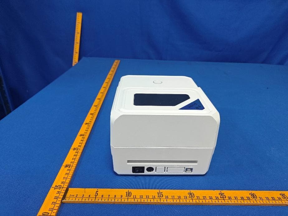
2BQHE-JP-B411
Dec 21, 2025Thermal label printer, thermal barcode printer, thermal waybill label machine
Equipment Class
DTS - Digital Transmission System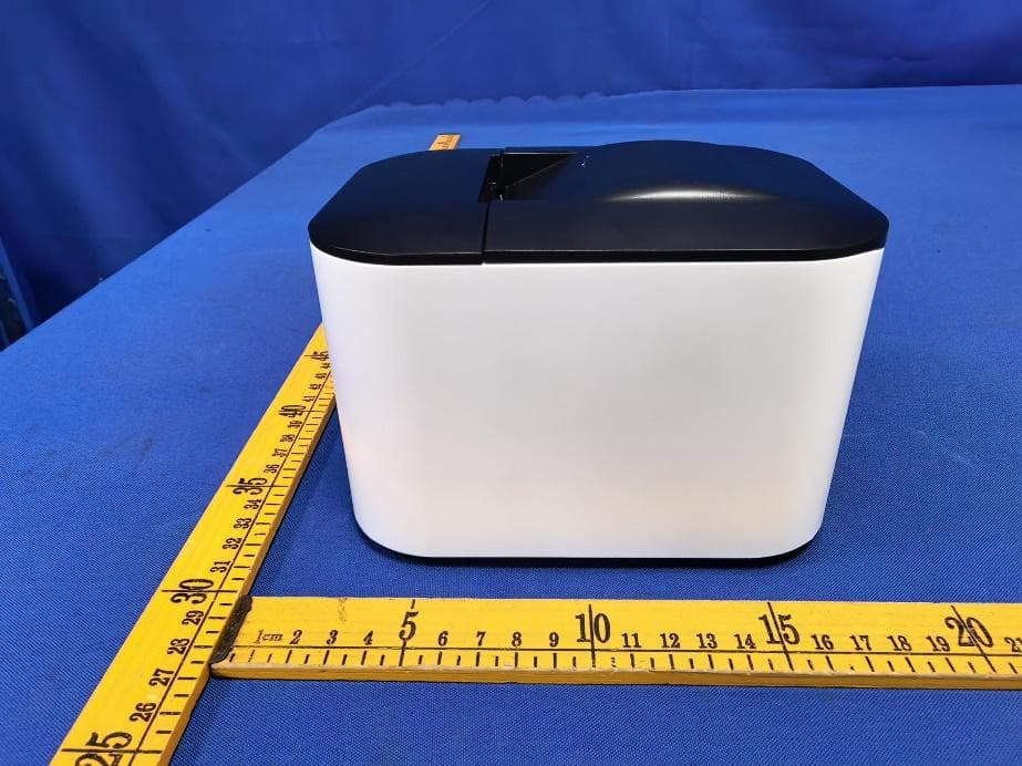
2BQHE-JP-B20
Dec 21, 2025Thermal label printer, thermal barcode printer, thermal waybill label machine
Equipment Class
DTS - Digital Transmission System